Page 484 of 969
 (3MZ-FE)
2200 Author�: Date�:
2005 LEXUS ES330 REPAIR MANUAL (RM")
A78711Main GearSub Gear
Service Bolt
A78712
10
12
3
4
5
67
89
A78713
10
1
2
3
4
5
6
7
89 14-108
- ENGINE MECHANICALCAMSHAFT (LH BANK) (3MZ-FE)
2200 Author�: Date�:
2005 LEXUS ES330 REPAIR MANUAL (RM1124U)
(b) Secure the exhaust camshaft sub gear to the main gear
with a service bolt.
Torque: 5.4 NVm (55 kgfVcm, 48 in.Vlbf)
Recommended service bolt
Thread diameter6 mm
Thread pitch1.0 mm
Bolt length16 to 20 mm
HINT:
When removing the camshaft, make certain that the torsional
spring force of the sub gear has been eliminated by installation
of the service bolt.
(c) Using several steps, loosen and remove the 10 bearing
cap bolts uniformly in the sequence shown in the illustra-
tion. Remove the 5 bearing caps and No. 3 camshaft.
NOTICE:
�Do not pry out the camshaft.
�Be careful not to damage the contact surface of the
cylinder head that receives the shaft thrust.
24. REMOVE NO.4 CAMSHAFT SUB-ASSY
(a) Using several steps, loosen and remove the 10 bearing
cap bolts uniformly in the sequence shown in the illustra-
tion. Remove the 5 bearing caps and No. 4 camshaft.
NOTICE:
�Do not pry out the camshaft.
�Be careful not to damage the contact surface of the
cylinder head that receives the shaft thrust.
(b) Remove the oil seal from the No. 4 camshaft.
25. REMOVE CAMSHAFT TIMING GEAR ASSY (See page 14-93)
26. REMOVE CAMSHAFT SUB GEAR NO.3 (See page 14-93)
SST 09960-10010 (09962-01000, 09963-00500)
27. INSTALL CAMSHAFT SUB GEAR NO.3 (See page 14-93)
SST 09960-10010 (09962-01000, 09963-00500)
28. INSTALL CAMSHAFT TIMING GEAR ASSY (See page 14-93)
Page 486 of 969
 (3MZ-FE)
2202 Author�: Date�:
2005 LEXUS ES330 REPAIR MANUAL (RM1124U)
(i) Usi")
A78743
10
1
23
4
5
6
7
8
9
A78744
Align
A05214
A78745
10
1
2
3
45
6
7
8
9 14-1 10
- ENGINE MECHANICALCAMSHAFT (LH BANK) (3MZ-FE)
2202 Author�: Date�:
2005 LEXUS ES330 REPAIR MANUAL (RM1124U)
(i) Using several steps, install and tighten the 10 bearing cap
bolts uniformly in the sequence shown in the illustration.
Torque: 16 NVm (163 kgfVcm, 12 ftVlbf)
30. INSTALL NO.3 CAMSHAFT SUB-ASSY
NOTICE:
Since the thrust clearance of the camshaft is small, the
camshaft must be kept level while being installed. If the
camshaft is not kept level, the cylinder head or camshaft
may be damaged. To avoid this, the following steps must
be carried out.
(a) Apply new engine oil to the thrust portion and journal of
the camshaft.
(b) Align the timing marks (1 dot marks) of the camshaft drive
and driven gears.
(c) Place the camshaft to the cylinder head.
(d) Install the 5 bearing caps in their proper locations.
(e) Apply a light coat of engine oil to the threads of the bear-
ing cap bolts.
(f) Using several steps, install and tighten the 10 bearing cap
bolts uniformly in the sequence shown in the illustration.
Torque: 16 NVm (163 kgfVcm, 12 ftVlbf)
(g) Remove the service bolt.
31. INSTALL TIMING BELT NO.3 COVER (See page 14-93)
32. INSTALL CAMSHAFT TIMING PULLEY (See page 14-93)
SST 09960-10010 (09962-01000, 09963-01000), 09249-63010
33. INSTALL TIMING BELT IDLER SUB-ASSY NO.2 (See page 14-93)
Page 587 of 969

11-7
2035 Author�: Date�:
2005 LEXUS ES330 REPAIR MANUAL (RM1124U)
2. CHECK FUEL PUMP OPERATION AND FUEL LEAK
(a) When using the")
A86347DLC3
Hand-held Tester
A62390
FP
+B
- FUELFUEL SYSTEM (3MZ-FE)
11-7
2035 Author�: Date�:
2005 LEXUS ES330 REPAIR MANUAL (RM1124U)
2. CHECK FUEL PUMP OPERATION AND FUEL LEAK
(a) When using the hand-held tester.
(1) Connect the hand-held tester to the DLC3.
(2) Turn the ignition switch ON and the hand-held tes-
ter ON.
NOTICE:
Do not start the engine.
(3) Select the ACTIVE TEST mode on the hand-held
tester.
(4) If you need help to select the ACTIVE TEST mode
on the hand-held tester, refer to the hand-held tes-
ter operator's manual.
(b) When not using the hand-held tester.
(1) Remove the circuit opening relay.
(2) Using a service wire, connect terminals FP and +B
of the engine room relay block.
NOTICE:
Pay due attention to the terminal connecting position to
avoid a malfunction.
(3) Turn the ignition switch ON, and check that the fuel
pump operates.
NOTICE:
Do not start the engine.
(c) Check that there are no fuel leaks after doing mainte-
nance anywhere on the fuel system.
Page 598 of 969
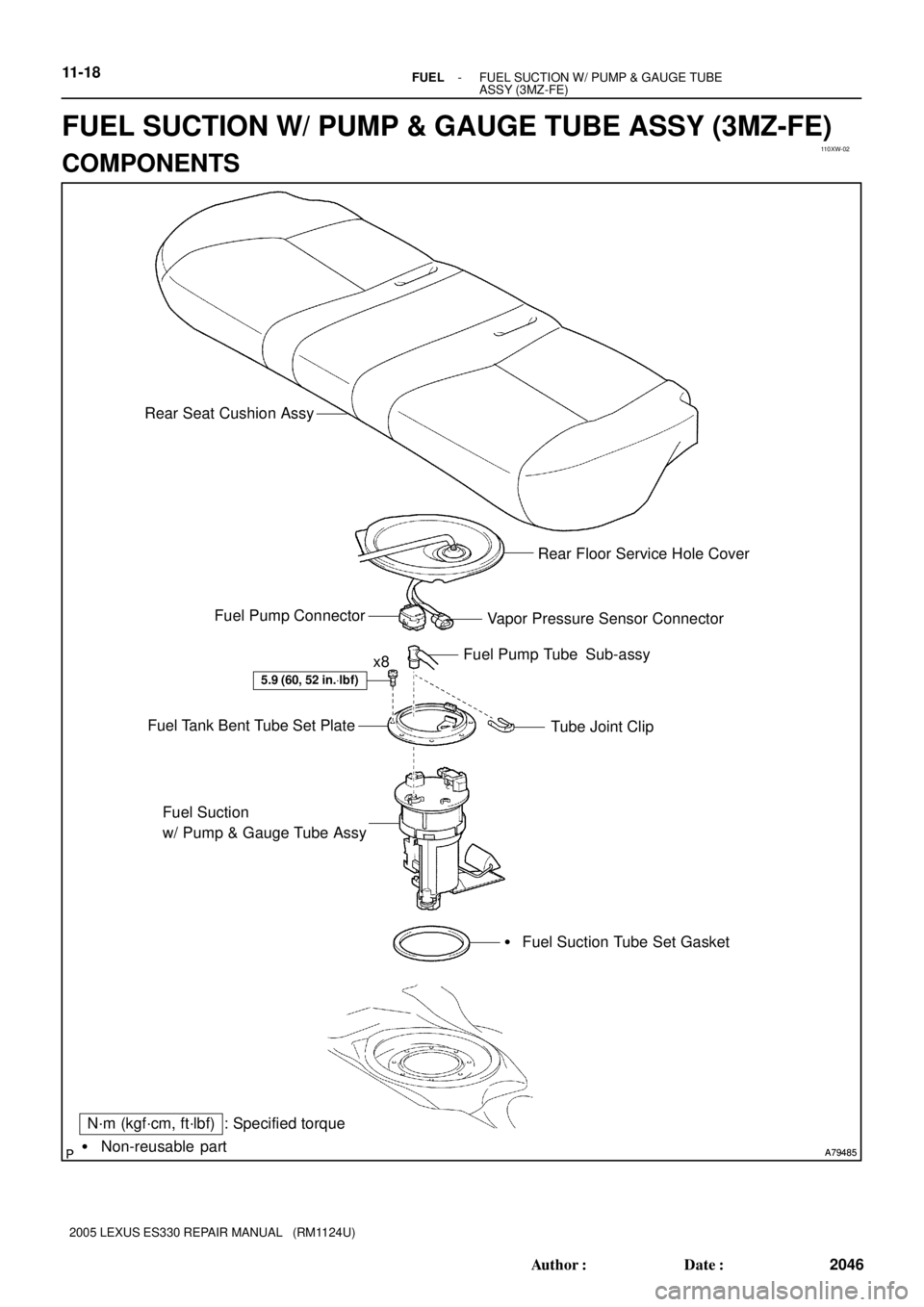
110XW-02
A79485 A79485� Non-reusable part
N´m (kgf´cm, ft´lbf) : Specified torque
5.9 (60, 52 in.Vlbf)
x8Fuel Pump Tube Sub-assy
Tube Joint Clip Fuel Tank Bent Tube Set Plate
Fuel Suction
w/ Pump & Gauge Tube Assy
� Fuel Suction Tube Set Gasket Vapor Pressure Sensor Connector Fuel Pump ConnectorRear Floor Service Hole Cover Rear Seat Cushion Assy
11-18- FUELFUEL SUCTION W/ PUMP & GAUGE TUBE
ASSY (3MZ-FE)
2046 Author�: Date�:
2005 LEXUS ES330 REPAIR MANUAL (RM1124U)
FUEL SUCTION W/ PUMP & GAUGE TUBE ASSY (3MZ-FE)
COMPONENTS
Page 600 of 969

(c)
A91017
Nylon Tube Fuel Tube Joint
O-ring
Tube Joint Clip Fuel Suction Plate
A79488
Tube Joint Clip
A79489
(b)
(b)
(b)(b)(b)
(b)
(b)
(b) 11-20
- FUELFUEL SUCTION W/ PUMP & GAUGE")
110XX-02
A79487
(b)
(c)
A91017
Nylon Tube Fuel Tube Joint
O-ring
Tube Joint Clip Fuel Suction Plate
A79488
Tube Joint Clip
A79489
(b)
(b)
(b)(b)(b)
(b)
(b)
(b) 11-20
- FUELFUEL SUCTION W/ PUMP & GAUGE TUBE
ASSY (3MZ-FE)
2048 Author�: Date�:
2005 LEXUS ES330 REPAIR MANUAL (RM1124U)
Removal & Installation and Disassembly & Reassembly
1. DISCHARGE FUEL SYSTEM PRESSURE (See page 11-1)
2. DISCONNECT ENGINE WIRE NO. 3 (BATTERY NEGATIVE TERMINAL)
3. REMOVE REAR SEAT CUSHION ASSY (See page 72-39)
4. REMOVE REAR FLOOR SERVICE HOLE COVER
(a) Remove the rear floor service hole cover.
(b) Disconnect the vapor pressure sensor connector.
(c) Disconnect the fuel pump connector.
5. REMOVE FUEL SUCTION W/ PUMP & GAUGE TUBE
ASSY
(a) Remove the tube joint clip, then pull out the fuel pump
tube.
NOTICE:
�Check around the connector for dirt or mud before
this operation. Remove the dirt if necessary.
�Be careful of mud because the fuel tube joint has an
O-ring which seals the pipe and connector that can
be contaminated.
�Do not use any tools in this operation.
�Do not bend or twist the nylon tube. Protect the con-
nector by covering it with a vinyl or plastic bag.
�When the pipe and connector are stuck, push and pull
the connector to release. Pull the connector carefully.
(b) Remove the 8 bolts, then remove the fuel tank vent tube
set plate.
Page 604 of 969

2052 Author�: Date�:
2005 LEXUS ES330 REPAIR MANUAL (RM1124U)
24. INSTALL FUE")
A79489Mark
A81595
Tube Joint ClipCollar
A79487
New Butyl Tape
11-24- FUELFUEL SUCTION W/ PUMP & GAUGE TUBE
ASSY (3MZ-FE)
2052 Author�: Date�:
2005 LEXUS ES330 REPAIR MANUAL (RM1124U)
24. INSTALL FUEL SUCTION W/ PUMP & GAUGE TUBE
ASSY
(a) Install a new gasket to the fuel suction tube w/ pump &
gauge.
(b) Install the fuel suction tube w/ pump & gauge to the fuel
tank.
NOTICE:
�Do not damage the fuel pump filter.
�Do not bend the arm of the fuel sender gauge.
(c) Align the mark of the fuel tank vent tube set plate with the
fuel suction tube w/ pump & gauge.
(d) Install the fuel tank bent tube set plate with the 8 bolts.
Torque: 5.9 NVm (60 kgfVcm, 52 in.Vlbf)
(e) Install the fuel pump tube with the tube joint clip.
NOTICE:
�Check the connected part for scratch or foreign ob-
jects.
�Check that the fuel tube joint is inserted securely.
�Check that the tube joint clip is on the collar of the fuel
tube joint.
�After installing the tube joint clip, check that the fuel
tube joint has not been pulled off.
25. CONNECT ENGINE WIRE NO. 3 (BATTERY NEGATIVE TERMINAL)
Torque: 5.4 NVm (55 kgfVcm, 48 in.Vlbf)
26. CHECK FOR FUEL LEAKS (See page 11-5)
27. INSTALL REAR FLOOR SERVICE HOLE COVER
(a) Connect the fuel pump connector.
(b) Connect the vapor pressure sensor connector.
(c) Using new butyl tape, install the rear floor service hole
cover.
28. INSTALL REAR SEAT CUSHION ASSY
29. SYSTEM INITIALIZATION (See page 19-15)
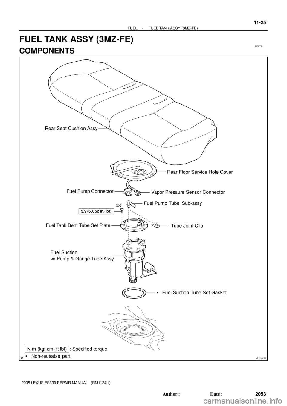
Page 605 of 969
110XY-01
A79485 A79485� Non-reusable part
N´m (kgf´cm, ft´lbf) : Specified torque
5.9 (60, 52 in.Vlbf)
x8Fuel Pump Tube Sub-assy
Tube Joint Clip Fuel Tank Bent Tube Set Plate
Fuel Suction
w/ Pump & Gauge Tube Assy
� Fuel Suction Tube Set Gasket Vapor Pressure Sensor Connector Fuel Pump ConnectorRear Floor Service Hole Cover Rear Seat Cushion Assy
- FUELFUEL TANK ASSY (3MZ-FE)
11-25
2053 Author�: Date�:
2005 LEXUS ES330 REPAIR MANUAL (RM1124U)
FUEL TANK ASSY (3MZ-FE)
COMPONENTS
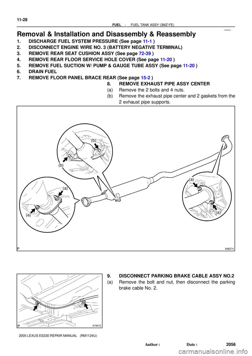
Page 608 of 969
110XZ-01
A86274
(a)
(b)
(a)
(a)
(a)
(b)
A79472
11-28
- FUELFUEL TANK ASSY (3MZ-FE)
2056 Author�: Date�:
2005 LEXUS ES330 REPAIR MANUAL (RM1124U)
Removal & Installation and Disassembly & Reassembly
1. DISCHARGE FUEL SYSTEM PRESSURE (See page 11-1)
2. DISCONNECT ENGINE WIRE NO. 3 (BATTERY NEGATIVE TERMINAL)
3. REMOVE REAR SEAT CUSHION ASSY (See page 72-39)
4. REMOVE REAR FLOOR SERVICE HOLE COVER (See page 11-20)
5. REMOVE FUEL SUCTION W/ PUMP & GAUGE TUBE ASSY (See page 11-20)
6. DRAIN FUEL
7. REMOVE FLOOR PANEL BRACE REAR (See page 15-2)
8. REMOVE EXHAUST PIPE ASSY CENTER
(a) Remove the 2 bolts and 4 nuts.
(b) Remove the exhaust pipe center and 2 gaskets from the
2 exhaust pipe supports.
9. DISCONNECT PARKING BRAKE CABLE ASSY NO.2
(a) Remove the bolt and nut, then disconnect the parking
brake cable No. 2.