Page 804 of 969
190SM-01
A81658
SST 1-A
SST 1-B
Turn
Hold
A81659
SST 2
Insert
SST 1
A81660
TurnSST1-A
A81661
SST 1-A
SST 1-B
Turn
Hold
- STARTING & CHARGINGGENERATOR ASSY (3MZ-FE)
19-23
2355 Author�: Date�:
2005 LEXUS ES330 REPAIR MANUAL (RM1124U)
OVERHAUL
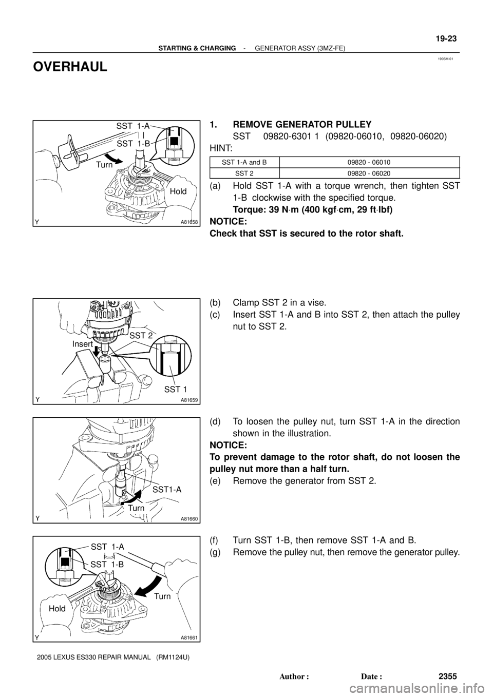
1. REMOVE GENERATOR PULLEY
SST 09820-6301 1 (09820-06010, 09820-06020)
HINT:
SST 1-A and B09820 - 06010
SST 209820 - 06020
(a) Hold SST 1-A with a torque wrench, then tighten SST
1-B clockwise with the specified torque.
Torque: 39 NVm (400 kgfVcm, 29 ftVlbf)
NOTICE:
Check that SST is secured to the rotor shaft.
(b) Clamp SST 2 in a vise.
(c) Insert SST 1-A and B into SST 2, then attach the pulley
nut to SST 2.
(d) To loosen the pulley nut, turn SST 1-A in the direction
shown in the illustration.
NOTICE:
To prevent damage to the rotor shaft, do not loosen the
pulley nut more than a half turn.
(e) Remove the generator from SST 2.
(f) Turn SST 1-B, then remove SST 1-A and B.
(g) Remove the pulley nut, then remove the generator pulley.
Page 805 of 969
A81662
Pulley
A81146
A81147
A81148
A81663
SST
HoldTurn
19-24
- STARTING & CHARGINGGENERATOR ASSY (3MZ-FE)
2356 Author�: Date�:
2005 LEXUS ES330 REPAIR MANUAL (RM1124U)
2. REMOVE GENERATOR BRUSH HOLDER ASSY
(a) Place the generator on the generator pulley.
(b) Remove the 3 nuts, then remove the generator rear end
cover.
(c) Remove the terminal insulator from the generator coil.
(d) Remove the 2 screws, then remove the generator brush
holder.
3. REMOVE GENERATOR COIL ASSY
(a) Remove the 4 bolts.
(b) Using SST, remove the generator coil.
SST 09950- 40011 (09951- 04020, 09952- 04010,
09953- 04020, 09954- 04010, 09955- 04071,
09957-04010, 09958-04011)
Page 806 of 969

19-25
2357 Author�: Date�:
2005 LEXUS ES330 REPA")
A81664
Generator Washer
A79305
Length
A79306
A88420
Ohmmeter Slip Ring
A88421
Ohmmeter Slip RingRotor Core
- STARTING & CHARGINGGENERATOR ASSY (3MZ-FE)
19-25
2357 Author�: Date�:
2005 LEXUS ES330 REPAIR MANUAL (RM1124U)
4. REMOVE GENERATOR ROTOR ASSY
(a) Remove the generator washer and generator rotor.
5. INSPECT GENERATOR BRUSH HOLDER ASSY
(a) Inspect the length.
(1) Using vernier calipers, measure the exposed brush
length.
Standard exposed brush length: 10.5 mm (0.413 in.)
Minimum exposed brush length: 4.5 mm (0.177 in.)
If the exposed brush length is less than minimum, replace the
generator brush holder.
6. INSPECT GENERATOR ROTOR ASSY
(a) Check that the bearing is not rough or worn.
If necessary, replace the generator rotor.
(b) Inspect the resistance.
(1) Using an ohmmeter, measure the resistance be-
tween the slip rings.
Resistance: 2.3 to 2.7W at 20�C (68�F)
If the resistance is not as specified, replace the generator rotor.
(c) Check the continuity.
(1) Using an ohmmeter, check that there is no continu-
ity between the slip ring and rotor core.
If there is continuity, replace the generator rotor.
(d) Check the appearance.
(1) Check that the slip rings are not rough or scored.
If rough or scored, replace the generator rotor.
Page 807 of 969
A75676
Diameter
A81670
Generator
PulleyGenerator Washer
A81671
Deep Socket
Wrench 21
A81148
A79315
Pin (f1.0 mm (0.039 in.))
19-26
- STARTING & CHARGINGGENERATOR ASSY (3MZ-FE)
2358 Author�: Date�:
2005 LEXUS ES330 REPAIR MANUAL (RM1124U)
(e) Inspect the diameter.
(1) Using vernier calipers, measure the slip ring diame-
ter.
Standard diameter:
14.2 to 14.4 mm (0.559 to 0.567 in.)
Minimum diameter: 14.0 mm (0.551 in.)
If the diameter is less than minimum, replace the generator ro-
tor.
7. INSTALL GENERATOR ROTOR ASSY
(a) Place the generator drive end frame on the generator
pulley.
(b) Install the generator rotor and generator washer.
8. INSTALL GENERATOR COIL ASSY
(a) Using a deep socket wrench 21 and press, press in the
generator coil carefully.
(b) Tighten the 4 bolts.
Torque: 5.8 NVm (59 kgfVcm, 51 in.Vlbf)
9. INSTALL GENERATOR BRUSH HOLDER ASSY
(a) While pushing the 2 brushes to inside the brush holder,
insert a pin (f1.0 mm (0.039 in.)) into the brush holder
hole.
Page 808 of 969

A81146
A81164
A81658
SST 1-A
SST 1-B
Turn
Hold
- STARTING & CHARGINGGENERATOR ASSY (3MZ-FE)
19-27
2359 Author�: Date�:
2005 LEXUS ES330 REPAIR MANUAL (RM1124U)
(b) In")
A81672
Pin (f1.0 mm (0.039 in.)
A81146
A81164
A81658
SST 1-A
SST 1-B
Turn
Hold
- STARTING & CHARGINGGENERATOR ASSY (3MZ-FE)
19-27
2359 Author�: Date�:
2005 LEXUS ES330 REPAIR MANUAL (RM1124U)
(b) Install the generator brush holder with the 2 screws.
Torque: 1.8 NVm (18 kgfVcm, 16 in.Vlbf)
(c) Pull out the pin (f1.0 mm (0.039 in.)) from the generator
brush holder.
(d) Install the terminal insulator.
NOTICE:
Pay attention to the mounting orientation of the terminal in-
sulator.
(e) Install the generator rear end cover with the 3 nuts.
Torque: 4.6 NVm (47 kgfVcm, 41 in.Vlbf)
10. INSTALL GENERATOR PULLEY
SST 09820-6301 1 (09820-06010, 09820-06020)
HINT:
SST 1-A and B09820 - 06010
SST 209820 - 06020
(a) Install the generator pulley to the rotor shaft by tightening
the generator pulley nut by hand.
(b) Hold SST 1-A with a torque wrench, then tighten SST
1-B clockwise with the specified torque.
Torque: 39 NVm (400 kgfVcm, 29 ftVlbf)
NOTICE:
Check that SST is secured to the rotor shaft.
Page 809 of 969
A81659
SST 2
Insert
SST 1
A81673
TurnSST1-A
A81661
SST 1-A
SST 1-B
Turn
Hold 19-28
- STARTING & CHARGINGGENERATOR ASSY (3MZ-FE)
2360 Author�: Date�:
2005 LEXUS ES330 REPAIR MANUAL (RM1124U)
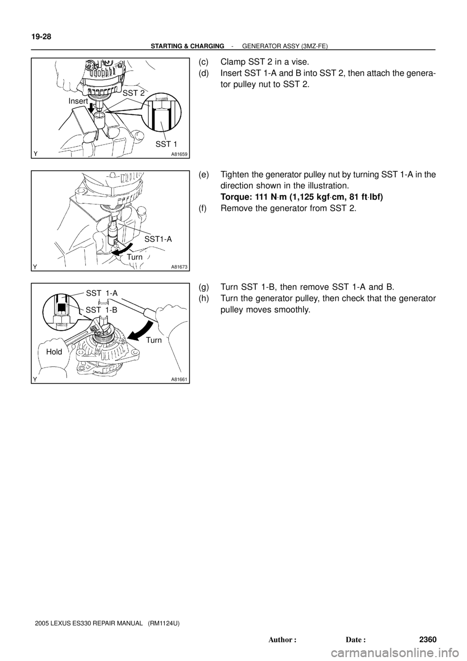
(c) Clamp SST 2 in a vise.
(d) Insert SST 1-A and B into SST 2, then attach the genera-
tor pulley nut to SST 2.
(e) Tighten the generator pulley nut by turning SST 1-A in the
direction shown in the illustration.
Torque: 111 NVm (1,125 kgfVcm, 81 ftVlbf)
(f) Remove the generator from SST 2.
(g) Turn SST 1-B, then remove SST 1-A and B.
(h) Turn the generator pulley, then check that the generator
pulley moves smoothly.
Page 915 of 969

BATTERY MAINTENANCE FOR IN±STOCK VEHICLES & PRE±DELIVERY ± PG009-02 September 12, 2002
Page 2 of 4
TOOLS & EQUIPMENTMANUFACTURERPART NUMBER
Fast Battery Charger**AssociatedASE6003
Fast Battery Charger**ChristieCAPPDQ
** These tools can be ordered through the Lexus Approved Dealer Equipment program by calling
1±800±368±6787.
NOTE:
The ªFast Battery Chargersº listed above have been tested and approved by Lexus.
These state±of±the±art ªsmartº chargers were designed to charge batteries at an
accelerated rate, without the possibility of damage. Using non±microprocessor
controlled battery chargers for fast charging purposes can damage the battery.
All vehicles are to be inspected according to the procedures listed below using the
MICROPRO 815 battery tester no more than 48 hours prior to customer vehicle delivery.
PRIOR TO TESTING:
If necessary, remove battery surface charge by turning on high beam headlights for 60
seconds, then let battery voltage recover for one minute.
1. Connect test clamps to battery.
(Display will show four zeros
indicating a good connection).
2. For cold battery (<32�F) or after
charge test, press TEST MODE key
until appropriate test is selected.
3. Input battery stock number.
NOTE:
Stock number must be used for
warranty cases because you cannot
read the warranty code if CCA/CA
rating is input.
4. Press STK#/Code key to start test.
NOTE:
Stock numbers are listed on the
reference card located in the tester's
cover. Stock numbers can also be
referenced on TIS. The TIS listings
will always have up±to±date
information.
Stock number location in TIS:
1. Go to TIS Home Page.
2. Click on ªDiagnostics.º
3. Click on ªMidtronics Battery Tester
Software.º
4. Click on ªStock Number Chart.º Recommended
Equipment
Inspection
Procedure