Page 763 of 969
2701I-09
- REAR SUSPENSIONREAR SUSPENSION SYSTEM
27-1
2383 Author�: Date�:
2005 LEXUS ES330 REPAIR MANUAL (RM1124U)
REAR SUSPENSION SYSTEM
PROBLEM SYMPTOMS TABLE
Use the table below to help you find the cause of the problem. The numbers indicate the priority of the likely
cause of the problem. Check each part in order. If necessary, replace these parts.
SymptomSuspect AreaSee page
Bottoming
1. Vehicle (Overloaded)
2. Spring (Weak)
3. Shock absorber (Worn)-
27-4
27-4
Sways/pitches
1. Tire (Worn or improperly inflated)
2. Stabilizer bar (Bent or broken)
3. Shock absorber (Worn)28-1
27-16
27-4
Rear wheel shimmy
1. Tire (Worn or improperly inflated)
2. Wheel (Out of balance)
3. Shock absorber (Worn)
4. Wheel alignment (Incorrect)
5. Hub bearing (Worn)28-1
28-1
27-4
26-5
27-3
30-2
Abnormal tire wear
1. Tire (Worn or improperly inflated)
2. Wheel alignment (Incorrect)
3. Shock absorber (Worn)
4. Suspension parts (Worn)28-1
26-5
27-3
27-4
-
Page 765 of 969

REAR WHEEL ALIGNMENT
ADJUSTMENT
1. INSPECT TIRE (S")
2704P-06
SA3213
A
DB
Front
C
C91810
C91811
- REAR SUSPENSIONREAR WHEEL ALIGNMENT
27-3
2385 Author�: Date�:
2005 LEXUS ES330 REPAIR MANUAL (RM1124U)
REAR WHEEL ALIGNMENT
ADJUSTMENT
1. INSPECT TIRE (See page 28-1)
2. MEASURE VEHICLE HEIGHT (See page 26-5)
NOTICE:
Before inspecting the wheel alignment, adjust the vehicle height to the specified value.
3. INSPECT TOE-IN
Toe-in:
Toe-in
(total)A + B: 0°22' ± 11' (0.4° ± 0.2°)
C - D: 4 ± 2 mm (0.16 ± 0.08 in.)
If the toe-in is not within the specified value, inspect and re-
place the suspension parts if necessary.
4. ADJUST TOE-IN
(a) Measure the lengths of the right and left No. 2 lower sus-
pension arms.
No. 2 lower suspension arm length difference:
1.0 mm (0.039 in.) or less
If the left-right difference is larger than 1.0 mm (0.039 in.), ad-
just it by following the procedures below.
(b) Loosen the lock nuts.
(c) Turn the right and left adjusting tube by an equal amount
to adjust toe-in.
HINT:
�Try to adjust the toe-in to the center value.
�One turn of the each adjusting tube will adjust the toe-in
by approximately 67' (1�12', 10.8 mm, 0.425 in.).
(d) Torque the lock nut.
Torque: 56 NVm (570 kgfVcm, 41 ftVlbf)
5. INSPECT CAMBER
Camber
Right-left error-1°23' ± 45' (-1.38° ± 0.75°)
45' (0.75°) or less
HINT:
Camber is not adjustable. If the measurement is not within the specification, inspect the suspension parts
for damaged and/or worn-out parts and replace them if necessary.
Page 770 of 969
C92644
w/o TEMS
w/ TEMSSST
C66631
27-8
- REAR SUSPENSIONSHOCK ABSORBER ASSY REAR LH
2390 Author�: Date�:
2005 LEXUS ES330 REPAIR MANUAL (RM1124U)
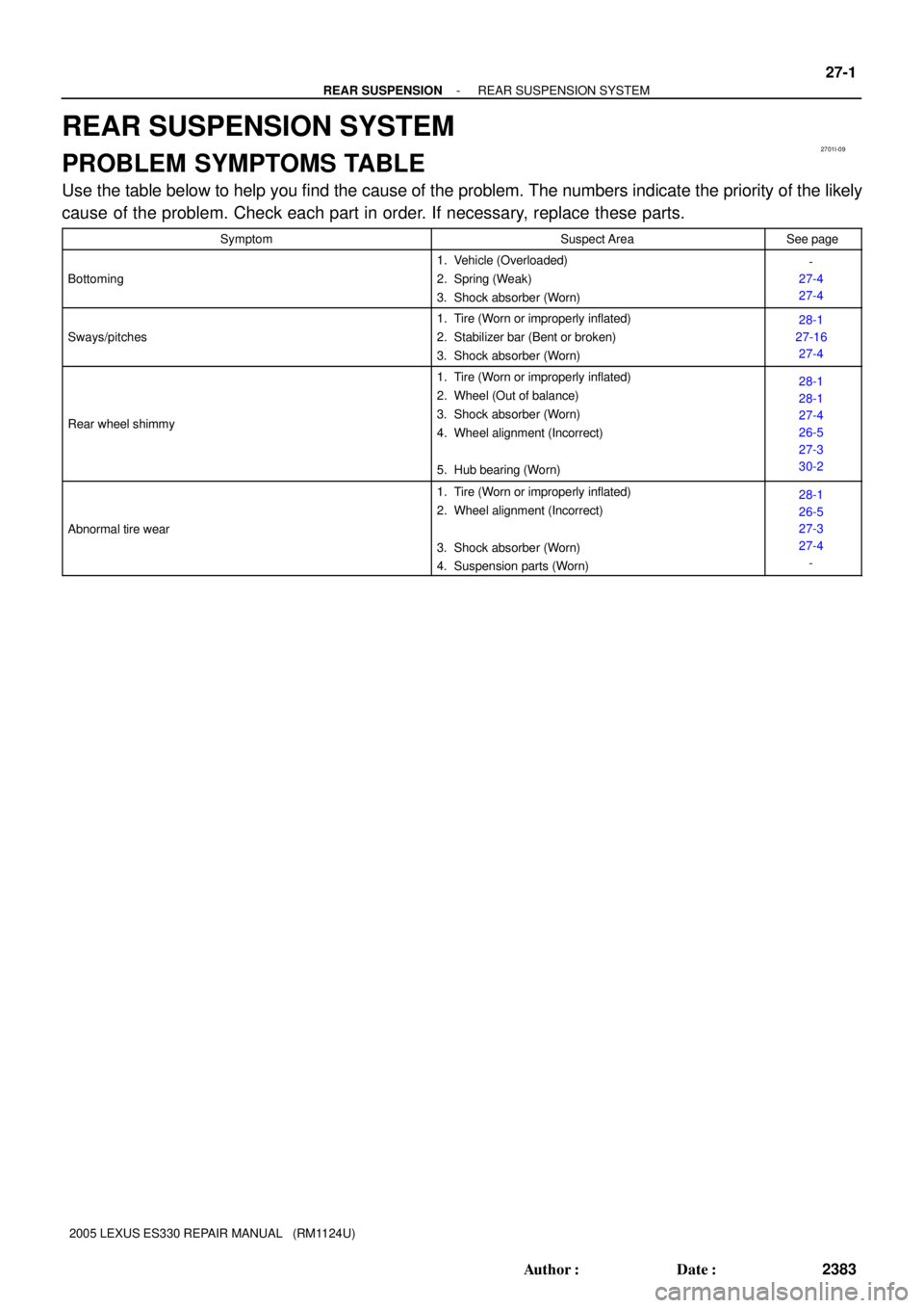
(d) w/o TEMS:
Tighten the nut in the center of suspension support.
(e) w/ TEMS:
Tighten the nut in the center of suspension support.
SST 09817-33190
Torque: 49 NVm (500 kgfVcm, 36 ftVlbf)
HINT:
If the shock absorber has not been disassembled, it is neces-
sary to tighten the nut.
21. INSTALL REAR SUSPENSION SUPOPORT NO.1 COVER LH (W/O H-TEMS SUSPENSION)
22. INSTALL REAR SEAT 3 POINT TYPE BELT ASSY OUTER (See page 61-15)
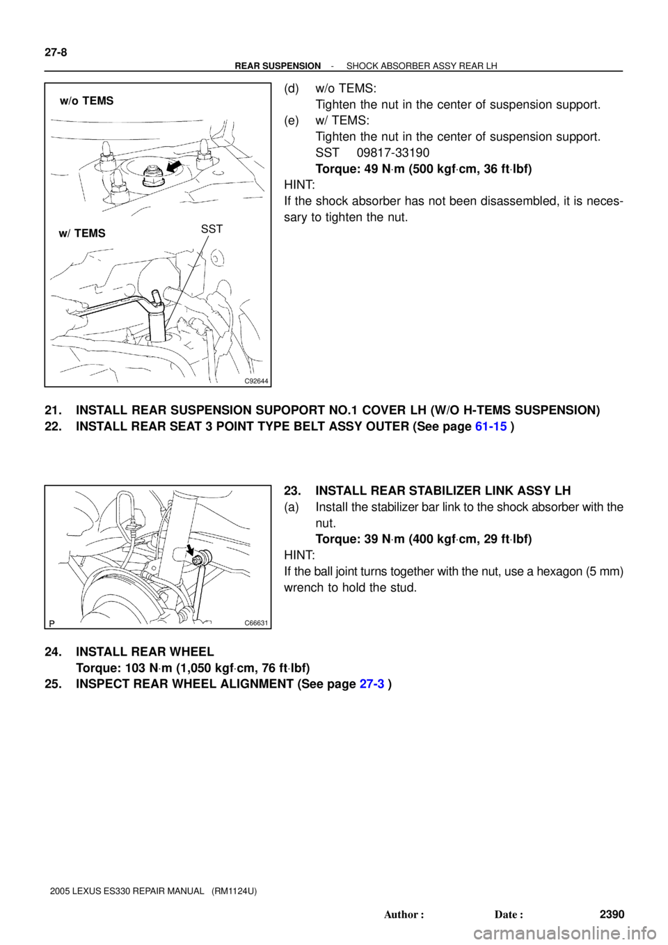
23. INSTALL REAR STABILIZER LINK ASSY LH
(a) Install the stabilizer bar link to the shock absorber with the
nut.
Torque: 39 NVm (400 kgfVcm, 29 ftVlbf)
HINT:
If the ball joint turns together with the nut, use a hexagon (5 mm)
wrench to hold the stud.
24. INSTALL REAR WHEEL
Torque: 103 NVm (1,050 kgfVcm, 76 ftVlbf)
25. INSPECT REAR WHEEL ALIGNMENT (See page 27-3)
Page 775 of 969

20. STABILIZE SUSPENSION
(a) Jack up the rear axle carrier,")
C91813
C82996
C82997
- REAR SUSPENSIONREAR SUSPENSION ARM ASSY NO.1 LH
27-13
2395 Author�: Date�:
2005 LEXUS ES330 REPAIR MANUAL (RM1124U)
20. STABILIZE SUSPENSION
(a) Jack up the rear axle carrier, placing a wooden block be-
tween them. Apply load to the suspension so that the
installed bolt of the suspension arm assy No. 1 (vehicle
side) is horizontally aligned with the center of the rear axle
hub.
21. FULLY TIGHTEN REAR SUSPENSION ARM ASSY
NO.1 LH
(a) Fully tighten the bolt.
Torque: 100 NVm (1,020 kgfVcm, 74 ftVlbf)
HINT:
While fixing the nut, turn the bolt.
22. FULLY TIGHTEN REAR SUSPENSION ARM ASSY NO.1 RH
HINT:
Fully tighten the RH side by the procedures with the LH side.
23. FULLY TIGHTEN REAR SUSPENSION ARM ASSY
NO.2 LH
(a) Fully tighten the bolt.
Torque: 100 NVm (1,020 kgfVcm, 74 ftVlbf)
HINT:
While fixing the nut, turn the bolt.
24. FULLY TIGHTEN REAR SUSPENSION ARM ASSY NO.2 RH
HINT:
Fully tighten the RH side by the procedures with the LH side.
25. FULLY TIGHTEN STRUT ROD ASSY REAR (See page 27-18)
26. INSTALL STABILIZER BAR REAR (See page 27-16)
27. INSTALL EXHAUST PIPE ASSY CENTER (See page 15-2)
28. INSTALL REAR WHEEL
Torque: 103 NVm (1,050 kgfVcm, 76 ftVlbf)
29. INSPECT REAR WHEEL ALIGNMENT (See page 27-3)
30. HEADLIGHT AIM ONLY (See page 65-15)
Page 777 of 969

- REAR SUSPENSIONREAR SUSPENSION ARM ASSY NO.2 LH
27-15
2397 Author�: Date�:
2005 LEXUS ES330 REPAIR MANUAL (RM1124U)
(b) Set the suspension arm in the position in the illustr")
B53747
38 mm (1.5 in.)
- REAR SUSPENSIONREAR SUSPENSION ARM ASSY NO.2 LH
27-15
2397 Author�: Date�:
2005 LEXUS ES330 REPAIR MANUAL (RM1124U)
(b) Set the suspension arm in the position in the illustration
and fully tighten the bolt.
Torque: 100 NVm (1,020 kgfVcm, 74 ftVlbf)
13. INSTALL REAR SUSPENSION MEMBER SUB-ASSY (See page 27-10)
14. TEMPORARILY TIGHTEN REAR SUSPENSION ARM ASSY NO.1 LH (See page 27-10)
15. TEMPORARILY TIGHTEN REAR SUSPENSION ARM ASSY NO.1 RH
HINT:
Temporarily tighten the RH side by the procedures with the LH side.
16. TEMPORARILY TIGHTEN REAR SUSPENSION ARM ASSY NO.2 LH (See page 27-10)
17. TEMPORARILY TIGHTEN REAR SUSPENSION ARM ASSY NO.2 RH
HINT:
Temporarily tighten the RH side by the procedures with the LH side.
18. TEMPORARILY TIGHTEN STRUT ROD ASSY REAR (See page 27-18)
19. CONNECT HEIGHT CONTROL SENSOR SUB-ASSY REAR RH (See page 65-33)
20. STABILIZE SUSPENSION (See page 27-10)
21. FULLY TIGHTEN REAR SUSPENSION ARM ASSY NO.1 LH (See page 27-10)
22. FULLY TIGHTEN REAR SUSPENSION ARM ASSY NO.1 RH
HINT:
Fully tighten the RH side by the procedures with the LH side.
23. FULLY TIGHTEN REAR SUSPENSION ARM ASSY NO.2 LH (See page 27-10)
24. FULLY TIGHTEN REAR SUSPENSION ARM ASSY NO.2 RH
HINT:
Fully tighten the RH side by the procedures with the LH side.
25. FULLY TIGHTEN STRUT ROD ASSY REAR (See page 27-18)
26. INSTALL STABILIZER BAR REAR (See page 27-16)
27. INSTALL EXHAUST PIPE ASSY CENTER (See page 15-2)
28. INSTALL REAR WHEEL
Torque: 103 NVm (1,050 kgfVcm, 76 ftVlbf)
29. INSPECT REAR WHEEL ALIGNMENT (See page 27-3)
30. HEADLIGHT AIM ONLY (See page 65-15)
Page 779 of 969
C93541
A
B
B53738
C91816
- REAR SUSPENSIONSTABILIZER BAR REAR
27-17
2399 Author�: Date�:
2005 LEXUS ES330 REPAIR MANUAL (RM1124U)
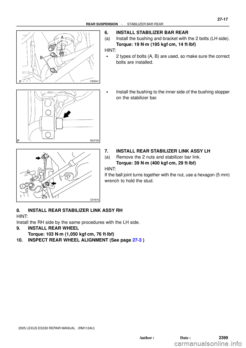
6. INSTALL STABILIZER BAR REAR
(a) Install the bushing and bracket with the 2 bolts (LH side).
Torque: 19 NVm (195 kgfVcm, 14 ftVlbf)
HINT:
�2 types of bolts (A, B) are used, so make sure the correct
bolts are installed.
�Install the bushing to the inner side of the bushing stopper
on the stabilizer bar.
7. INSTALL REAR STABILIZER LINK ASSY LH
(a) Remove the 2 nuts and stabilizer bar link.
Torque: 39 NVm (400 kgfVcm, 29 ftVlbf)
HINT:
If the ball joint turns together with the nut, use a hexagon (5 mm)
wrench to hold the stud.
8. INSTALL REAR STABILIZER LINK ASSY RH
HINT:
Install the RH side by the same procedures with the LH side.
9. INSTALL REAR WHEEL
Torque: 103 NVm (1,050 kgfVcm, 76 ftVlbf)
10. INSPECT REAR WHEEL ALIGNMENT (See page 27-3)
Page 781 of 969
B53740
B53741
B53739
- REAR SUSPENSIONSTRUT ROD ASSY REAR
27-19
2401 Author�: Date�:
2005 LEXUS ES330 REPAIR MANUAL (RM1124U)
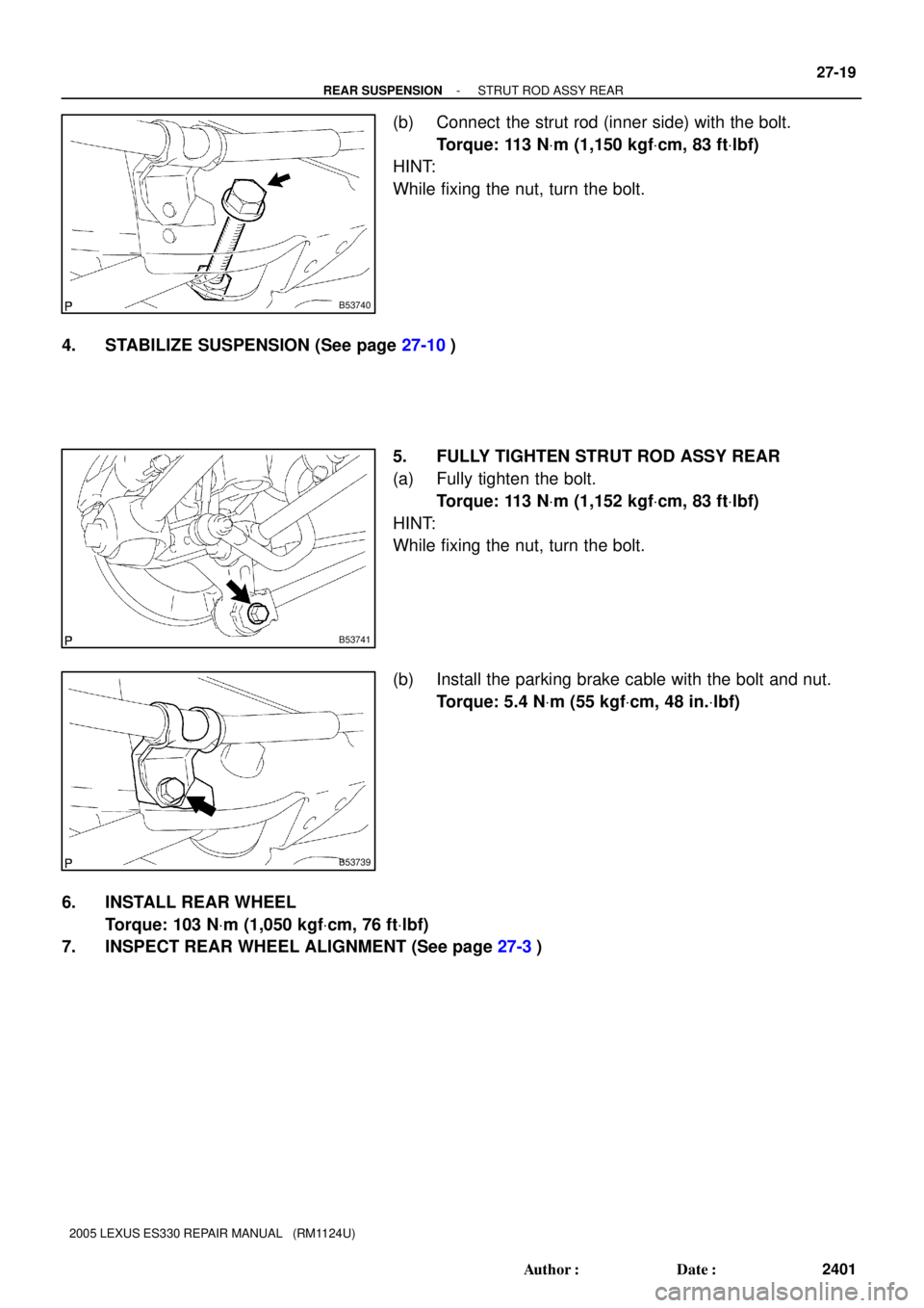
(b) Connect the strut rod (inner side) with the bolt.
Torque: 113 NVm (1,150 kgfVcm, 83 ftVlbf)
HINT:
While fixing the nut, turn the bolt.
4. STABILIZE SUSPENSION (See page 27-10)
5. FULLY TIGHTEN STRUT ROD ASSY REAR
(a) Fully tighten the bolt.
Torque: 113 NVm (1,152 kgfVcm, 83 ftVlbf)
HINT:
While fixing the nut, turn the bolt.
(b) Install the parking brake cable with the bolt and nut.
Torque: 5.4 NVm (55 kgfVcm, 48 in.Vlbf)
6. INSTALL REAR WHEEL
Torque: 103 NVm (1,050 kgfVcm, 76 ftVlbf)
7. INSPECT REAR WHEEL ALIGNMENT (See page 27-3)
Page 811 of 969

PROBLEM SYMPTOMS TABLE
Use the table below to help you find the cause of the problem. The number")
5002K-07
50-2
- STEERING COLUMNSTEERING
2563 Author�: Date�:
2005 LEXUS ES330 REPAIR MANUAL (RM1124U)
PROBLEM SYMPTOMS TABLE
Use the table below to help you find the cause of the problem. The numbers indicate the priority of the likely
cause of the problem. Check each part in the order shown. If necessary, repair or replace these parts.
SymptomSuspect AreaSee page
Hard steering
1. Tires (Improperly inflated)
2. Power steering fluid level (Low)
3. Drive belt (Loose)
4. Front wheel alignment (Incorrect)
5. Steering system joints (Worn)
6. Suspension arm ball joints (Worn)
7. Steering column (Binding)
8. Power steering vane pump
9. Power steering gear28-1
51-3
51-3
51-3
26-5
-
26-16
-
51-9
51-21
Poor return
1. Tires (Improperly inflated)
2. Front wheel alignment (Incorrect)
3. Steering column (Binding)
4. Power steering gear28-1
26-5
-
51-21
Excessive play
1. Steering system joints (Worn)
2. Suspension arm ball joints (Worn)
3. Intermediate shaft, Sliding yoke (Worn)
4. Front wheel bearing (Worn)
5. Power steering gear-
26-16
-
30-19
51-21
Abnormal noise
1. Power steering fluid level (Low)
2. Steering system joints (Worn)
3. Power steering vane pump
4. Power steering gear51-3
-
51-9
51-21