Page 557 of 969
A78323
10�
45�
- ENGINE MECHANICALCYLINDER BLOCK ASSY (3MZ-FE)
14-181
2273 Author�: Date�:
2005 LEXUS ES330 REPAIR MANUAL (RM1124U)
(b) After applying the specified torque, rotate the drain cock
clockwise as shown in the illustration.
Torque: 39 NVm (398 kgfVcm, 29 ftVlbf)
NOTICE:
�Install the drain cock within 3 minutes after applying
adhesive.
�Do not expose the drain cock to coolant within 1 hour
after installing.
�Do not rotate the drain cock by more than 1 revolution
(360�) after tightening the drain cock with the speci-
fied torque.
�Do not loosen the drain cock after setting it correctly.
Page 750 of 969

32. REMOVE POWER STE")
F40911
SST
C83179
Wire Cylinder End
Stopper
F40542
SST
51-28
- POWER STEERINGRACK & PINION POWER STEERING GEAR ASSY
2603 Author�: Date�:
2005 LEXUS ES330 REPAIR MANUAL (RM1124U)
32. REMOVE POWER STEERING CONTROL VALVE
UPPER OIL SEAL
(a) Using SST and a press, remove the control valve upper
bearing and power steering control valve upper oil seal
from the control valve housing.
SST 09950- 70010 (09951- 07150), 09950- 60010
(09951-00250)
33. REMOVE CYLINDER END STOPPER
(a) Using a screwdriver and a hammer, turn the cylinder end
stopper clockwise until the wire end is visible through the
service hole.
(b) Using a screwdriver and a hammer, turn the cylinder end
stopper counterclockwise, and remove the wire and cylin-
der end stopper.
34. REMOVE POWER STEERING RACK
(a) Remove the power steering rack and power steering rack bush.
35. REMOVE POWER STEERING RACK BUSH
(a) Remove the power steering rack bush from the power
steering rack.
(b) Using SST, remove the rack bush oil seal.
SST 09527-2101 1, 09612-24014 (09613-22011)
(c) Using a screwdriver, remove the O-ring from the power
steering rack bush.
Page 753 of 969

F05730
Vinyl Tape
Power
Steering
Bush
F40546
Cylinder
End Stopper
Wire
F41507
SST
F40912
SST
SST
F40913
SST
- POWER STEERINGRACK & PINION POWER STEERING GEAR ASSY
51-31
2606 Author�: Date�:
2005 LEXUS ES330 REPAIR MANUAL (RM1124U)
(c) To prevent rack bush oil seal lip damage, wind vinyl tape
around the power steering rack end, and apply power
steering fluid.
(d) Install the power steering rack bush to the power steering
rack.
43. INSTALL CYLINDER END STOPPER
(a) Align the installation hole for the wire of the cylinder end
stopper with the slot of the rack housing.
(b) Install a new wire into the cylinder end stopper.
(c) Using a screwdriver, turn the cylinder end stopper clock-
wise by 450 � 50�.
44. AIR TIGHTNESS TEST
(a) Install SST to the rack housing.
SST 09631-12071 (09633-00010)
(b) Apply vacuum of 53 kPa (400 mmHg, 15.75 in.Hg) for
about 30 seconds.
(c) Check that there is no change in the vacuum.
If there is a change in the vacuum, check the installation of the
oil seals.
45. I N S TA L L P O W E R S T E E R I N G C O N T R O L VA LV E
UPPER OIL SEAL
(a) Coat a control valve upper bearing and a new power
steering control valve upper oil seal with power steering
fluid.
(b) Using SST and a press, install the power steering control
valve upper oil seal.
SST 09950- 70010 (09951- 07150), 09950- 60010
(09951-00180, 09952-06010, 09951-00320)
(c) Using SST and a press, install the control valve upper
bearing.
SST 09950- 70010 (09951- 07150), 09950- 60010
(09951-00180, 09952-06010, 09951-00340)
Page 793 of 969

2344 Author�: Date�:
2005 LEXUS ES330 REPAIR MANUAL (RM112")
A76677
Length
A88418
Ohmmeter
A81655
FreeLock
A81656
Apply Grease
A82440
Snap Ring
Pliers
19-12
- STARTING & CHARGINGSTARTER ASSY (3MZ-FE)
2344 Author�: Date�:
2005 LEXUS ES330 REPAIR MANUAL (RM1124U)
9. INSPECT STARTER COMMUTATOR END FRAME
ASSY
(a) Inspect the length.
(1) Using vernier calipers, measure the brush length.
Standard length: 9.0 mm (0.354 in.)
Minimum length: 4.0 mm (0.158 in.)
If the length is less than minimum, replace the starter commuta-
tor end frame.
(b) Check the continuity.
(1) Using an ohmmeter, check that there is no continu-
ity between the positive (+) and negative (- )
brushes.
If there is continuity, repair or replace the starter commutator
end frame.
10. INSPECT STARTER DRIVE HOUSING ASSY (W/
CLUTCH & DRIVE LEVER & CENTER BEARING)
(a) Check the operation.
(1) Rotate the clutch pinion gear counterclockwise,
then check that it turns freely. Try to rotate the clutch
pinion gear clockwise and check that it locks.
If necessary, replace the starter drive housing.
11. INSTALL PLANETARY GEAR
(a) Apply grease to the planetary gears and pin parts of the
planetary shaft.
(b) Install the 3 planetary gears to the starter drive housing.
12. INSTALL STARTER ARMATURE ASSY
(a) Apply grease to the plate washer and armature shaft.
(b) Install the starter armature to the starter commutator end
frame.
(c) Using snap ring pliers, install the plate washer and a new
snap ring.
Page 804 of 969
190SM-01
A81658
SST 1-A
SST 1-B
Turn
Hold
A81659
SST 2
Insert
SST 1
A81660
TurnSST1-A
A81661
SST 1-A
SST 1-B
Turn
Hold
- STARTING & CHARGINGGENERATOR ASSY (3MZ-FE)
19-23
2355 Author�: Date�:
2005 LEXUS ES330 REPAIR MANUAL (RM1124U)
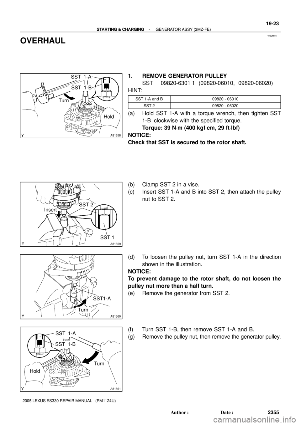
OVERHAUL
1. REMOVE GENERATOR PULLEY
SST 09820-6301 1 (09820-06010, 09820-06020)
HINT:
SST 1-A and B09820 - 06010
SST 209820 - 06020
(a) Hold SST 1-A with a torque wrench, then tighten SST
1-B clockwise with the specified torque.
Torque: 39 NVm (400 kgfVcm, 29 ftVlbf)
NOTICE:
Check that SST is secured to the rotor shaft.
(b) Clamp SST 2 in a vise.
(c) Insert SST 1-A and B into SST 2, then attach the pulley
nut to SST 2.
(d) To loosen the pulley nut, turn SST 1-A in the direction
shown in the illustration.
NOTICE:
To prevent damage to the rotor shaft, do not loosen the
pulley nut more than a half turn.
(e) Remove the generator from SST 2.
(f) Turn SST 1-B, then remove SST 1-A and B.
(g) Remove the pulley nut, then remove the generator pulley.
Page 808 of 969

A81146
A81164
A81658
SST 1-A
SST 1-B
Turn
Hold
- STARTING & CHARGINGGENERATOR ASSY (3MZ-FE)
19-27
2359 Author�: Date�:
2005 LEXUS ES330 REPAIR MANUAL (RM1124U)
(b) In")
A81672
Pin (f1.0 mm (0.039 in.)
A81146
A81164
A81658
SST 1-A
SST 1-B
Turn
Hold
- STARTING & CHARGINGGENERATOR ASSY (3MZ-FE)
19-27
2359 Author�: Date�:
2005 LEXUS ES330 REPAIR MANUAL (RM1124U)
(b) Install the generator brush holder with the 2 screws.
Torque: 1.8 NVm (18 kgfVcm, 16 in.Vlbf)
(c) Pull out the pin (f1.0 mm (0.039 in.)) from the generator
brush holder.
(d) Install the terminal insulator.
NOTICE:
Pay attention to the mounting orientation of the terminal in-
sulator.
(e) Install the generator rear end cover with the 3 nuts.
Torque: 4.6 NVm (47 kgfVcm, 41 in.Vlbf)
10. INSTALL GENERATOR PULLEY
SST 09820-6301 1 (09820-06010, 09820-06020)
HINT:
SST 1-A and B09820 - 06010
SST 209820 - 06020
(a) Install the generator pulley to the rotor shaft by tightening
the generator pulley nut by hand.
(b) Hold SST 1-A with a torque wrench, then tighten SST
1-B clockwise with the specified torque.
Torque: 39 NVm (400 kgfVcm, 29 ftVlbf)
NOTICE:
Check that SST is secured to the rotor shaft.
Page 890 of 969
PRE±DELIVERY SERVICE (PDS) INFORMATION FOR ES 330 ± PD002-03 August 26, 2003
Page 3 of 9
REMOVAL OF FRONT EMERGENCY TOWING EYELET AND INSTALLATION OF
TOWING EYELET HOLE COVER (PERFORMED AT PORT)
1. Remove the emergency towing eyelet
from the front bumper by turning
counterclockwise.
NOTE:
If it is hard to loosen the emergency
towing eyelet, use a steel bar.
2. Place the removed emergency
towing eyelet in the tool tray in the
luggage compartment.
3. Install the front towing eyelet hole
cover which is stored in the glove box
onto the front bumper as shown in
the diagram. ITEM NO. 2:
Emergency Towing Eyelet
Installation
Procedure
Page 906 of 969
Lexus Supports ASE CertificationPage 1 of 2
Title:
FRONT EMERGENCY TOWING EYELET &
EYELET HOLE COVER
Models:
'05 ± '06 ES 330
Technical Service
Information Bulletin
August 26, 2005
PD037-05
The 2005 ± 2006 model year ES 330 is shipped with a front emergency towing eyelet.
Follow the procedure below to remove the eyelet and save for customer use.
�2005 ± 2006 model year ES 330 vehicles.
OP CODEDESCRIPTIONTIMEOFPT1T2
N/ANot Applicable to Warranty±±±±
1. Remove the emergency towing
eyelet from the front bumper by
turning counterclockwise.
NOTE:
If it is hard to loosen the emergency
towing eyelet, use a steel bar.
PRE-DELIVERY SERVICE
Introduction
Applicable
Vehicles
Warranty
Information
Emergency Towing Eyelet
Installation
Procedure

 INFORMATION FOR ES 330 ± PD002-03 August 26, 2003
Page 3 of 9
REMOVAL OF FRONT EMERGENCY TOWING EYELET AND INSTALLATION OF
TOWING EYELET HOLE COVER (PERFORMED AT PORT)
1.")
