Page 445 of 969

14-69
2161 Author�: Date�:
2005 LEXUS ES330 REPAIR MANUAL (RM1124U)
90. INSTALL TIMING BELT TENSIONER ASSY
(a) Set th")
A36238
A78326
Turn
A05052
A36239
- ENGINE MECHANICALPARTIAL ENGINE ASSY (3MZ-FE)
14-69
2161 Author�: Date�:
2005 LEXUS ES330 REPAIR MANUAL (RM1124U)
90. INSTALL TIMING BELT TENSIONER ASSY
(a) Set the timing belt tensioner upright on the press.
(b) Slowly press in the push rod.
NOTICE:
Do not apply pressure more than 9.8 kN (1,000 kgf, 2,205
lbf) to the rod.
(c) Align the holes of the push rod and housing, then pass a
1.5 mm hexagon wrench through the holes to keep the
setting position of the push rod.
(d) Release the press.
(e) Temporarily install the tensioner with the 2 bolts. Alter-
nately tighten the 2 bolts.
Torque: 27 NVm (280 kgfVcm, 20 ftVlbf)
NOTICE:
Be sure to tighten the bolts uniformly. Installing the ten-
sioner at an angle may cause failure of its proper operation.
(f) Remove the 1.5 mm hexagon wrench from the tensioner.
(g) Turn the crankshaft 2 revolutions slowly, then align the
timing mark of the crankshaft timing pulley with the oil
pump body.
NOTICE:
Always turn the crankshaft clockwise.
(h) Check that the timing marks of the RH and LH timing pul-
leys are aligned with the timing marks of the timing belt
No. 3 cover as shown in the illustration.
If the marks are not aligned, remove the timing belt and reinstall
it.
(i) Remove the crankshaft pulley bolt.
91. INSTALL TIMING BELT GUIDE NO.2
(a) Install the timing belt guide with the cup side facing the en-
gine front.
Page 456 of 969
A78756
SST
A78759
Clamp
Clamp
P18814
A78326
Turn 14-80
- ENGINE MECHANICALTIMING BELT (3MZ-FE)
2172 Author�: Date�:
2005 LEXUS ES330 REPAIR MANUAL (RM1124U)
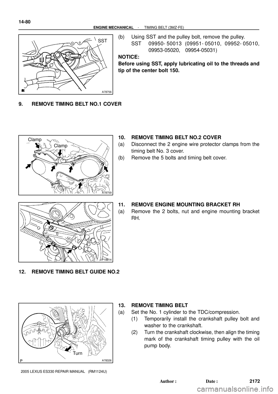
(b) Using SST and the pulley bolt, remove the pulley.
SST 09950- 50013 (09951- 05010, 09952- 05010,
09953-05020, 09954-05031)
NOTICE:
Before using SST, apply lubricating oil to the threads and
tip of the center bolt 150.
9. REMOVE TIMING BELT NO.1 COVER
10. REMOVE TIMING BELT NO.2 COVER
(a) Disconnect the 2 engine wire protector clamps from the
timing belt No. 3 cover.
(b) Remove the 5 bolts and timing belt cover.
11. REMOVE ENGINE MOUNTING BRACKET RH
(a) Remove the 2 bolts, nut and engine mounting bracket
RH.
12. REMOVE TIMING BELT GUIDE NO.2
13. REMOVE TIMING BELT
(a) Set the No. 1 cylinder to the TDC/compression.
(1) Temporarily install the crankshaft pulley bolt and
washer to the crankshaft.
(2) Turn the crankshaft clockwise, then align the timing
mark of the crankshaft timing pulley with the oil
pump body.
Page 457 of 969

(6) (1)(4) (2)(3)
- ENGINE MECHANICALTIMING BELT (3MZ-FE)
14-81
2173 Author�: Date�:
2005 LEXUS ES330 REPAIR MANUAL (RM1124U)
(3) Check that th")
A05052
A52840
A78327
Turn
Approximately 60�
A78702
(5)
(6) (1)(4) (2)(3)
- ENGINE MECHANICALTIMING BELT (3MZ-FE)
14-81
2173 Author�: Date�:
2005 LEXUS ES330 REPAIR MANUAL (RM1124U)
(3) Check that the timing marks of the camshaft timing
pulleys and the timing belt No. 3 cover are aligned.
If not, turn the crankshaft by 1 revolution (360�).
(4) Remove the crankshaft pulley bolt.
(b) If reusing the timing belt, check that there are 3 installa-
tion marks on the timing belt as shown in the illustration.
(1) If the installation marks have disappeared, put new
installation marks on the timing belt before remov-
ing.
(c) Set the No. 1 cylinder to approximately 60� BTDC/com-
pression.
(1) Turn the crankshaft counterclockwise by approxi-
mately 60�.
NOTICE:
If the timing belt is disengaged, having the crankshaft
pulley set at the wrong angle can cause contact of the pis-
ton head with the valve head when removing the camshaft
timing pulley and camshaft, which causes damage. So al-
ways set the crankshaft pulley at the correct angle.
(d) Remove the timing belt tensioner.
NOTICE:
Do not reinstall the tensioner with its plunger extended.
(e) Remove the timing belt in this order.
1stNo. 1 idler pulley
2ndRH camshaft timing pulley
3rdNo. 2 idler pulley
4thLH camshaft timing pulley
5thWater pump pulley
6thCrankshaft timing pulley
Page 459 of 969
 (2)
(3) (4)
(5)
(6)
- ENGINE MECHANICALTIMING BELT (3MZ-FE)
14-83
2175 Author�: Date�:
2005 LEXUS ES330 REPAIR MANUAL (RM1124U)
(e) T")
A82349
Turn
Approximately 60�
A78751
SST
A05062
A52840
A78702(1) (2)
(3) (4)
(5)
(6)
- ENGINE MECHANICALTIMING BELT (3MZ-FE)
14-83
2175 Author�: Date�:
2005 LEXUS ES330 REPAIR MANUAL (RM1124U)
(e) Turn the crankshaft counterclockwise by approximately
60�.
NOTICE:
To prevent contact of the piston head with the valve head,
set the crankshaft pulley at the 60� BTDC/compression
position.
(f) Using SST, turn the timing pulleys, then align the timing
marks of the timing pulleys with the timing belt No. 3 cover.
SST 09960-10010 (09962-01000, 09963-01000)
(g) Turn the crankshaft, then align the timing mark of the
crankshaft timing pulley with the oil pump body.
(h) Align the front mark on the timing belt so it faces forward.
(i) Align the installation mark on the timing belt with the tim-
ing mark of the crankshaft timing pulley.
(j) Align the installation marks on the timing belt with the tim-
ing marks of the camshaft timing pulleys.
(k) Install the timing belt in this order.
1stCrankshaft timing pulley
2ndWater pump pulley
3rdLH camshaft timing pulley
4thNo. 2 idler pulley
5thRH camshaft timing pulley
6thNo. 1 idler pulley
Page 460 of 969

2176 Author�: Date�:
2005 LEXUS ES330 REPAIR MANUAL (RM1124U)
16. INSTALL TIMING BELT TENSIONER ASSY
(a) Set the timing")
A36238
A78326
Turn
A05052
A36239
14-84
- ENGINE MECHANICALTIMING BELT (3MZ-FE)
2176 Author�: Date�:
2005 LEXUS ES330 REPAIR MANUAL (RM1124U)
16. INSTALL TIMING BELT TENSIONER ASSY
(a) Set the timing belt tensioner upright on the press.
(b) Slowly press in the push rod.
NOTICE:
Do not apply pressure more than 9.8 kN (1,000 kgf, 2,205
lbf) to the rod.
(c) Align the holes of the push rod and housing, then pass a
1.5 mm hexagon wrench through the holes to keep the
setting position of the push rod.
(d) Release the press.
(e) Temporarily install the tensioner with the 2 bolts. Alter-
nately tighten the 2 bolts.
Torque: 27 NVm (280 kgfVcm, 20 ftVlbf)
NOTICE:
Be sure to tighten the bolts uniformly. Installing the ten-
sioner at an angle may cause failure of its proper operation.
(f) Remove the 1.5 mm hexagon wrench from the tensioner.
(g) Turn the crankshaft 2 revolutions slowly, then align the
timing mark of the crankshaft timing pulley with the oil
pump body.
NOTICE:
Always turn the crankshaft clockwise.
(h) Check that the timing marks of the RH and LH timing pul-
leys are aligned with the timing marks of the timing belt
No. 3 cover as shown in the illustration.
If the marks are not aligned, remove the timing belt and reinstall
it.
(i) Remove the crankshaft pulley bolt.
17. INSTALL TIMING BELT GUIDE NO.2
(a) Install the timing belt guide with the cup side facing the en-
gine front.
Page 471 of 969
 (3MZ-FE)
14-95
2187 Author�: Date�:
2005 LEXUS ES330 REPAIR MANUAL (RM1124U)
27. REMOVE NO.2 CAMSHAFT
(a) Using")
A78709
10
1
2
3
4
5
67
8
9
A05739
A05740
P12596
- ENGINE MECHANICALCAMSHAFT (RH BANK) (3MZ-FE)
14-95
2187 Author�: Date�:
2005 LEXUS ES330 REPAIR MANUAL (RM1124U)
27. REMOVE NO.2 CAMSHAFT
(a) Using several steps, loosen and remove the 10 bearing
cap bolts uniformly in the sequence shown in the illustra-
tion. Remove the 5 bearing caps and No. 2 camshaft.
NOTICE:
�Do not pry out the camshaft.
�Be careful not to damage the contact surface of the
cylinder head that receives the shaft thrust.
(b) Remove the oil seal from the No. 2 camshaft.
28. REMOVE CAMSHAFT TIMING GEAR ASSY
NOTICE:
Do not remove or install the camshaft timing gear (VVT-i)
unless you are replacing the VVT-i or camshaft.
(a) Clamp the camshaft in a vise on the hexagonal lobe.
NOTICE:
Be careful not to damage the camshaft.
(b) Using a 46 mm socket wrench, remove the lock nut by
turning it clockwise.
NOTICE:
�Remove it with the lock pin engaged and locked at the
most retard angle position.
�The lock nut has LH threads.
�Never use any tools other than the socket wrench.
Other tools will deform the cam angle rotor.
(c) Remove the camshaft VVT-i.
NOTICE:
Never remove the 3 bolts on the gear.
If it is difficult to remove VVT-i, tap it lightly using a plastic-faced
hammer, then remove it.
29. REMOVE CAMSHAFT SUB GEAR
(a) Clamp the camshaft in a vise on the hexagonal lobe.
NOTICE:
Be careful not to damage the camshaft.
Page 472 of 969
A78715
SST
A52353
P12595
A78732
Camshaft
Sub Gear
Camshaft Gear
Bolt Washer Wave Washer
A52353
14-96
- ENGINE MECHANICALCAMSHAFT (RH BANK) (3MZ-FE)
2188 Author�: Date�:
2005 LEXUS ES330 REPAIR MANUAL (RM1124U)
(b) Using SST, turn the sub gear counterclockwise, then re-
move the service bolt.
SST 09960-10010 (09962-01000, 09963-00500)
(c) Using snap ring pliers, remove the snap ring.
(d) Remove the wave washer, camshaft sub gear and cam-
shaft gear bolt washer.
30. INSTALL CAMSHAFT SUB GEAR
(a) Clamp the camshaft in a vise on the hexagonal lobe.
NOTICE:
Be careful not to damage the camshaft.
(b) Install the camshaft gear bolt washer and camshaft sub
gear.
HINT:
Attach the pins on the gears to the gear bolt washer ends.
(c) Install the wave washer.
(d) Using snap ring pliers, install the snap ring.
Page 473 of 969
 (3MZ-FE)
14-97
2189 Author�: Date�:
2005 LEXUS ES330 REPAIR MANUAL (RM1124U)
(e) Using SST, align the holes of the camshaft main")
A78733
SST
A78734
Align
A05738
- ENGINE MECHANICALCAMSHAFT (RH BANK) (3MZ-FE)
14-97
2189 Author�: Date�:
2005 LEXUS ES330 REPAIR MANUAL (RM1124U)
(e) Using SST, align the holes of the camshaft main gear and
sub gear by turning the camshaft sub gear counterclock-
wise, then temporarily install a service bolt.
SST 09960-10010 (09962-01000, 09963-00500)
(f) Align the gear teeth of the main gear and sub gear, then
tighten the service bolt.
Torque: 5.4 NVm (55 kgfVcm, 48 in.Vlbf)
NOTICE:
Be careful not to damage the camshaft journals.
HINT:
When installing the camshaft, make certain that the torsional
spring force of the sub gear has been eliminated by installation
of the service bolt.
31. INSTALL CAMSHAFT TIMING GEAR ASSY
(a) Align the alignment pin with the alignment pin groove,
then install the VVT-i on the camshaft.
NOTICE:
Install it with the lock pin engaged and locked at the most
retard angle position.
(b) Apply engine oil to the nut, mounting surface of the VVT-i
and screw threads.
NOTICE:
�Be sure to apply the oil, otherwise the specified
torque cannot be obtained.
�New nut must be used when replacing the VVT-i unit.
(c) Using a 46 mm socket wrench, install and tighten a lock
nut by turning it counterclockwise.
Torque: 150 NVm (1,530 kgfVcm, 111 ftVlbf)
NOTICE:
�The lock nut has LH threads.
�Never use any tools other than the socket wrench.
Other tools will deform the cam angle rotor.
32. INSTALL NO.2 CAMSHAFT
NOTICE:
Since the thrust clearance of the camshaft is small, the
camshaft must be kept level while being installed. If the
camshaft is not kept level, the cylinder head or camshaft
may be damaged. To avoid this, the following steps must
be carried out.
(a) Apply new engine oil to the thrust portion and journal of
the camshaft.