Page 220 of 969

40-21
2536 Author�: Date�:
2005 LEXUS ES330 REPAIR MANUAL (RM1124U)
TRANSMISSION WIRE (U151E)
REPLACEME")
4010V-04
C91925
D30865
AT0103
C91927
- AUTOMATIC TRANSMISSION / TRANSTRANSMISSION WIRE (U151E)
40-21
2536 Author�: Date�:
2005 LEXUS ES330 REPAIR MANUAL (RM1124U)
TRANSMISSION WIRE (U151E)
REPLACEMENT
1. REMOVE ENGINE UNDER COVER NO.1
2. DRAIN AUTOMATIC TRANSAXLE FLUID
(a) Remove the drain plug, gasket, and drain ATF.
(b) Install a new gasket and drain plug.
Torque: 49 NVm (500 kgfVcm, 36 ftVlbf)
3. REMOVE AUTOMATIC TRANSAXLE OIL PAN
SUB-ASSY
(a) Remove the 18 bolts, oil pan and gasket.
NOTICE:
Some fluid will remain in the oil pan. Remove all the pan
bolts, and carefully remove the oil pan assembly.
(b) Remove the 2 magnets from the oil pan.
(c) Examine particles in pan.
(1) Use the removed magnets to collect steel chips.
Look carefully at the chips and particles in the pan
and the magnet to anticipate the type of wear you
will find in the transaxle.
Steel (magnetic): bearing, gear and plate wear
Brass (non-magnetic): bearing wear
4. DISCONNECT TRANSMISSION WIRE
(a) Disconnect the 7 shift solenoid valve connectors.
(b) Remove the bolt and lock plate, and disconnect the ATF
temperature sensor.
Page 223 of 969

2539 Author�: Date�:
2005 LEXUS ES330 REPAIR MANUAL (RM1124U)
TRANSMISSION VALVE BODY")
4010W-04
C91925
D30865
AT0103
C91927
40-24
- AUTOMATIC TRANSMISSION / TRANSTRANSMISSION VALVE BODY ASSY (U151E)
2539 Author�: Date�:
2005 LEXUS ES330 REPAIR MANUAL (RM1124U)
TRANSMISSION VALVE BODY ASSY (U151E)
REPLACEMENT
1. REMOVE ENGINE UNDER COVER NO.1
2. DRAIN AUTOMATIC TRANSAXLE FLUID
(a) Remove the drain plug, gasket, and drain ATF.
(b) Install a new gasket and drain plug.
Torque: 49 NVm (500 kgfVcm, 36 ftVlbf)
3. REMOVE AUTOMATIC TRANSAXLE OIL PAN
SUB-ASSY
(a) Remove the 18 bolts, oil pan and gasket.
NOTICE:
Some fluid will remain in the oil pan. Remove all the pan
bolts, and carefully remove the oil pan assembly.
(b) Remove the 2 magnets from the oil pan.
(c) Examine particles in pan.
(1) Use the removed magnets to collect steel chips.
Look carefully at the chips and particles in the pan
and the magnet to anticipate the type of wear you
will find in the transaxle.
Steel (magnetic): bearing, gear and plate wear
Brass (non-magnetic): bearing wear
4. DISCONNECT TRANSMISSION WIRE
(a) Disconnect the 7 shift solenoid valve connectors.
(b) Remove the bolt and lock plate, and disconnect the ATF
temperature sensor.
Page 227 of 969
D30865
C91925
40-28
- AUTOMATIC TRANSMISSION / TRANSTRANSMISSION VALVE BODY ASSY (U151E)
2543 Author�: Date�:
2005 LEXUS ES330 REPAIR MANUAL (RM1124U)
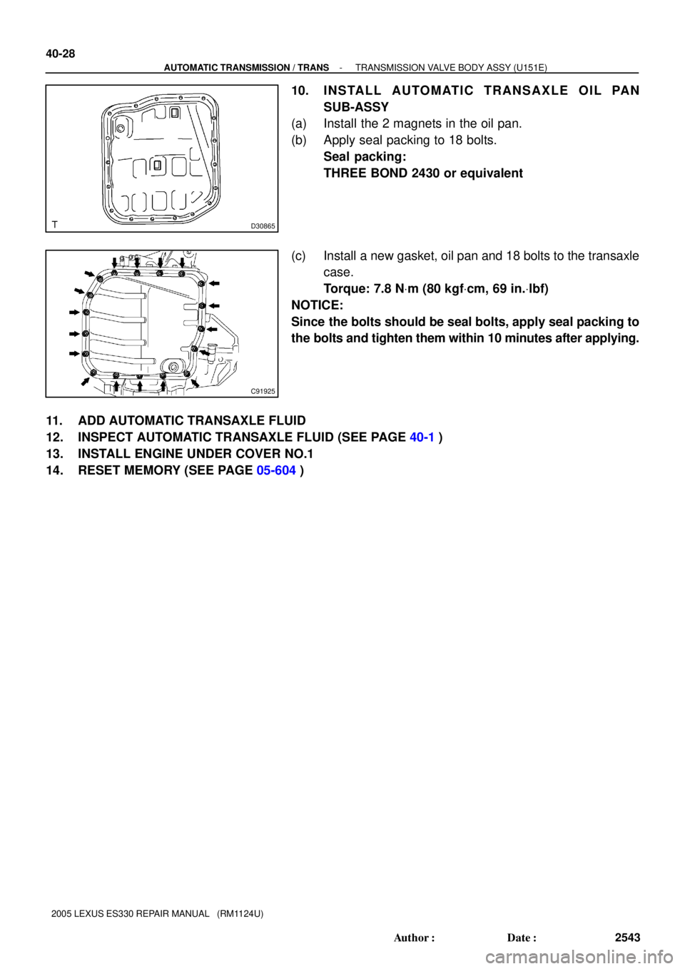
10. I N S TA L L A U TO M AT I C T R A N S A X L E O I L PA N
SUB-ASSY
(a) Install the 2 magnets in the oil pan.
(b) Apply seal packing to 18 bolts.
Seal packing:
THREE BOND 2430 or equivalent
(c) Install a new gasket, oil pan and 18 bolts to the transaxle
case.
Torque: 7.8 NVm (80 kgfVcm, 69 in.Vlbf)
NOTICE:
Since the bolts should be seal bolts, apply seal packing to
the bolts and tighten them within 10 minutes after applying.
11. ADD AUTOMATIC TRANSAXLE FLUID
12. INSPECT AUTOMATIC TRANSAXLE FLUID (SEE PAGE 40-1)
13. INSTALL ENGINE UNDER COVER NO.1
14. RESET MEMORY (SEE PAGE 05-604)
Page 228 of 969

40-29
2544 Author�: Date�:
2005 LEXUS ES330 REPAIR MANUAL (RM1124U)
FRONT DIFFERENTIAL O")
4010X-04
D25831
SST
D25832
SST
D25833
SST
- AUTOMATIC TRANSMISSION / TRANSFRONT DIFFERENTIAL OIL SEAL (U151E)
40-29
2544 Author�: Date�:
2005 LEXUS ES330 REPAIR MANUAL (RM1124U)
FRONT DIFFERENTIAL OIL SEAL (U151E)
REPLACEMENT
1. REMOVE FRONT WHEELS
2. REMOVE ENGINE UNDER COVER NO.1
3. DRAIN AUTOMATIC TRANSAXLE FLUID
(a) Remove the drain plug, gasket and drain ATF.
(b) Install a new gasket and drain plug.
Torque: 49 NVm (500 kgfVcm, 36 ftVlbf)
4. REMOVE FRONT DRIVE SHAFT ASSY RH (SEE PAGE 30-8)
5. REMOVE FRONT DRIVE SHAFT ASSY LH (SEE PAGE 30-8)
6. REMOVE TRANSAXLE HOUSING OIL SEAL
(a) Using SST, pull out the oil seal.
SST 09308-00010
7. REMOVE DIFFERENTIAL SIDE BEARING RETAINER
OIL SEAL
(a) Using SST, pull out the oil seal.
SST 09308-00010
8. INSTALL DIFFERENTIAL SIDE BEARING RETAINER
OIL SEAL
(a) Using SST and a hammer, drive in a new oil seal.
SST 09316-6001 1 (09316-00011)
Oil seal drive in depth:
0 � 0.5 mm (0 � 0.020 in.)
(b) Coat the lip of the oil seal with MP grease.
SST 09316-6001 1 (09316-00011)
Page 367 of 969

2425 Author�: Date�:
2005 LEXUS ES330 REPAIR MANUAL (RM1124U)
18. INSTALL FRONT AXL")
C83852F45465
C97690F45054
C83023
30-22
- DRIVE SHAFT / PROPELLER SHAFTFRONT AXLE HUB SUB-ASSY LH (From July, 2003)
2425 Author�: Date�:
2005 LEXUS ES330 REPAIR MANUAL (RM1124U)
18. INSTALL FRONT AXLE HUB LH HOLE SNAP RING
(a) Using snap ring pliers, install a new front axle hub LH hole
snap ring.
19. INSTALL FRONT WHEEL BEARING DUST
DEFLECTOR NO.1 LH
(a) Using SST and a hammer, install the bearing dust deflec-
tor No.1 LH.
SST 09316- 60011 (09316- 00011, 09316- 00031),
09608-32010
HINT:
Aligh the hole for the speed sensor in the bearing dust deflector
No.1 LH with the steering knuckle.
20. INSTALL LOWER BALL JOINT ASSY FRONT LH
(a) Install the lower ball joint assy front LH and tighten the nut.
Torque: 123 NVm (1,254 kgfVcm, 90 ftVlbf)
(b) Install a new cotter pin.
NOTICE:
If the holes for the cotter pin are not aligned, tighten the nut up to 60� further.
21. INSTALL FRONT AXLE ASSY LH
(a) Install the front axle assy LH with the 2 bolts and nuts to
the shock absorber assy front LH.
Torque: 210 NVm (2,141 kgfVcm, 155 ftVlbf)
NOTICE:
�Only when reusing the bolts and nuts, apply the small
amount of engine oil to the screw part of the nuts.
�Do not excessively push out the front axle assy LH.
�Be careful not to damage the outboard joint boot.
�Be careful not to damage the speed sensor rotor.
22. INSTALL FRONT SUSPENSION ARM SUB-ASSY LOWER NO.1 LH (SEE PAGE 30-8)
23. INSTALL TIE ROD ASSY LH (SEE PAGE 30-8)
24. INSTALL FRONT DISC
Page 377 of 969

14-1
2093 Author�: Date�:
2005 LEXUS ES330 REPAIR MANUAL")
141C0-02
A82940
Vane Pump
CrankshaftGenerator Measuring Points for Belt Deflection
or Tension
Compressor
- ENGINE MECHANICALENGINE (3MZ-FE)
14-1
2093 Author�: Date�:
2005 LEXUS ES330 REPAIR MANUAL (RM1124U)
ENGINE (3MZ-FE)
INSPECTION
1. INSPECT ENGINE COOLANT (See page 16-1)
2. INSPECT ENGINE OIL
3. INSPECT BATTERY
Standard specific gravity: 1.25 to 1.29 at 20�C (68�F)
4. INSPECT AIR CLEANER FILTER ELEMENT SUB-ASSY
5. INSPECT SPARK PLUG (See page 18-3)
6. INSPECT V-RIBBED BELT
(a) Belt deflection:
Pressing force: 98 N (10 kgf, 22 lbf)
New Belt
mm (in.)Used Belt
mm (in.)
V-ribbed Belt
(For fan and generator)9.1 to 10.5
(0.358 to 0.413)11 to 13.5
(0.433 to 0.531)
V-ribbed Belt
(For vane pump)8 to 10
(0.315 to 0.394)11 to 14
(0.433 to 0.551)
(b) Belt tension:
New Belt
N (kg , lb)Used Belt
N (kg , lb)
V-ribbed Belt
(For fan and generator)637 to 735
(65 to 75 , 143 to 165)392 to 588
(40 to 60 , 88 to 132)
V-ribbed Belt
(For vane pump)588 to 686
(60 to 70 , 132 to 154)245 to 392
(25 to 40 , 55 to 88)
NOTICE:
�Check the drive belt deflection at the specified point.
�When installing a new belt, set its tension value as
specified.
�When inspecting a belt which is used for over 5 min-
utes, apply the specification of ºUsed beltº.
�When reinstalling a belt which is used for over 5 min-
utes, adjust its belt deflection and tension to the inter-
mediate value of each specification in ºUsed beltº.
�The V- ribbed belt tension and deflection value
should be checked after 2 revolutions of engine
cranking.
�When using a belt tension gauge, confirm the accura-
cy first by using a master gauge.
7. INSPECT IGNITION TIMING
(a) Warm up engine.
(b) When using the hand-held tester or OBD II scan tool:
(1) Connect the hand-held tester or OBD II scan tool
to the DLC3.
(2) Enter DATA LIST MODE on the hand-held tester or
OBD II scan tool.
Ignition timing: 8 to 12� BTDC
HINT:
Refer to the hand-held tester or OBD II scan tool operator's
manual if you need help to select DATA LIST.
Page 379 of 969

14-3
2095 Author�: Date�:
2005 LEXUS ES330 REPAIR MANUAL (RM1124U)
9. INSPECT COMPRESSION
(a) Warm up and stop the engine.
(b) Remove the")
P19471
Compression Gauge
- ENGINE MECHANICALENGINE (3MZ-FE)
14-3
2095 Author�: Date�:
2005 LEXUS ES330 REPAIR MANUAL (RM1124U)
9. INSPECT COMPRESSION
(a) Warm up and stop the engine.
(b) Remove the intake air surge tank (see page 11-13).
(c) Disconnect the injector connectors.
(d) Remove the ignition coils.
(e) Remove the spark plugs.
(f) Inspect the cylinder compression pressure.
(1) Insert a compression gauge into the spark plug
hole.
SST 09992-00500
(2) Fully open the throttle.
(3) While cranking the engine, measure the compres-
sion pressure.
Compression pressure:
1.5 MPa (15.3 kgf/cm
2, 218 psi)
Minimum pressure:
1.0 MPa (10.2 kgf/cm
2, 145 psi)
Difference between each cylinder:
100 kPa (1.0 kgf/cm
2, 15 psi)
NOTICE:
�Always use a fully-charged battery to obtain engine
speed of 250 rpm or more.
�Check the other cylinder's compression pressure in
the same way.
�This measurement must be done as quickly as pos-
sible.
(4) If the cylinder compression is low, pour a small
amount of engine oil into the cylinder through the
spark plug hole, then inspect again.
HINT:
�If adding oil increases the compression, the piston rings
and/or cylinder bore may be worn or damaged.
�If pressure stays low, the valve may be sticking or seated
improperly, or there may be leakage past the gasket.
10. INSPECT CO/HC
HINT:
The ECM properly controls the CO/HC concentration in the emission gas.
(a) Start the engine.
(b) Run the engine at 2,500 rpm for approximately 180 seconds.
(c) Insert the CO/HC meter testing probe at least 40 cm (1.3 ft) into the tailpipe during idling.
(d) Check the CO/HC concentration at idle and/or at 2,500 rpm.
HINT:
When doing the 2 mode (with the engine is at idle and at 2,500 rpm) tests, these measuring order are pre-
scribed by the applicable local regulations.
If the CO/HC concentration does not comply with the regulations, troubleshoot in the order given below.
(1) Check the heated oxygen sensor operation (see page 05-126).
Page 383 of 969

(b)
(b)(a)
(a)
A36719
P18805
- ENGINE MECHANICALVALVE CLEARANCE (3MZ-FE)
14-7
2099 Author�: Date�:
2005 LEXUS ES330 REPAIR MANUAL (RM1124U)
VALVE CLEARANCE (3MZ-FE)
ADJUSTMENT
1.")
141J7-02
A78541
(b)
(b)
(b)(a)
(a)
A36719
P18805
- ENGINE MECHANICALVALVE CLEARANCE (3MZ-FE)
14-7
2099 Author�: Date�:
2005 LEXUS ES330 REPAIR MANUAL (RM1124U)
VALVE CLEARANCE (3MZ-FE)
ADJUSTMENT
1. DISCONNECT BATTERY NEGATIVE TERMINAL
2. DRAIN ENGINE COOLANT (See page 16-9)
3. REMOVE FRONT FENDER APRON SEAL RH
4. REMOVE FRONT SUSPENSION UPPER BRACE CENTER (W/O TEMS) (See page 10-1 1)
5. REMOVE V-BANK COVER SUB-ASSY (See page 10-1 1)
6. REMOVE AIR CLEANER CAP SUB-ASSY (See page 10-1 1)
7. REMOVE EMISSION CONTROL VALVE SET (See page 11-13)
8. REMOVE INTAKE AIR SURGE TANK (See page 11-13)
9. REMOVE RADIATOR HOSE INLET
10. REMOVE IGNITION COIL ASSY
11. REMOVE CYLINDER HEAD COVER SUB-ASSY
(a) Remove the 2 engine wire harness clamps.
(b) Remove the 3 nuts, then disconnect the engine wire har-
ness.
(c) Remove the 9 bolts and cylinder head cover.
12. REMOVE CYLINDER HEAD COVER SUB-ASSY LH
(a) Using an E6 Torx) socket wrench, remove the 2 bolts and
disconnect the engine wire harness protector.
(b) Remove the 9 bolts and cylinder head cover.
13. INSPECT VALVE CLEARANCE
(a) Turn the crankshaft pulley, then align the timing notch with
the timing mark º0º of the timing belt No. 1 cover.
(b) Check that the valve lifters on the intake side of the No.
1 cylinder are not pushed by the cam.
If the valve lifters are pushed, turn the crankshaft by 1 revolution
(360�) and align the marks as above.