Page 269 of 424
The system will consist of tire pressure monitoring
sensors attached to each wheel through the valve stem
mounting hole, a central receiver module and an amber
colored Indicator Lamp. A sensor is located in the spare
wheel if the vehicle is equipped with a matching full size
spare wheel and tire assembly.
NOTE:For vehicles with optional wheel/tire sizes and
significantly different tire placard pressures, the placard
pressure value and the low-pressure threshold value is
re-programmable at your authorized dealer to accommo-
date the customer selected wheel/tire combinations rec-
ommended by DaimlerChrysler.CAUTION!
The TPM system has been optimized for the original
equipment tires and wheels. TPM system pressures
have been established for the tire size equipped on
your vehicle. Undesirable system operation or sen-
sor damage may result when using replacement
equipment that is not of the same size, type, and/or
style. After-market wheels can cause sensor damage.
Do not use tire sealant from a can, or balance beads
if your vehicle is equipped with a TPM system, as
damage to the sensors may result.
STARTING AND OPERATING 269
5
Page 270 of 424
CAUTION!
After inspecting or adjusting the tire pressure al-
ways reinstall the valve stem cap. This will prevent
moisture and dirt from entering the valve stem,
which could damage the wheel rim sensor.
NOTE:
•The TPM system can inform the driver of a low tire
pressure condition.
•The TPM system is not intended to replace normal tire
care and maintenance, nor to provide warning of a tire
failure or condition.
•The TPM system should not be used as a tire pressure
gauge while adjusting your tire pressure.
Tire Pressure Monitoring — Premium System
The Tire Pressure Monitor System (TPM) system uses
wireless technology with wheel rim mounted electronic
sensors to monitor tire pressure levels. Sensors mounted
to each wheel as part of the valve stem transmit tire
pressure readings to the Receiver Module. The wheel
sensors monitor tire pressure, and status for all four
active road tires and the spare tire. The spare tire pressure
is monitored, but not displayed.
NOTE:It is particularly important, for you to check the
tire pressure in all of your tires regularly and to maintain
the proper pressure.
The Tire Pressure Monitoring Indicator Lamp will
illuminate in the instrument cluster, and an au-
dible chime will be activated when one or more
tire pressures is low. The Tire Pressure Monitoring Indi-
cator Lamp will flash on and off for ten seconds when a
270 STARTING AND OPERATING
Page 271 of 424
system fault is detected. The flash cycle will repeat every
ten minutes or until the fault condition is removed and
reset.
The Tire Pressure Monitoring System consists of the
following components:
•Receiver Module
•4/5 Wheel Sensors
•4 Wheel Sensor Trigger Modules
•Tire Pressure Monitoring System Display Messages in
the EVIC
•Amber Colored Tire Pressure Monitoring Indicator
Lamp
The system consists of tire pressure monitoring sensors
attached to each wheel through the valve stem mounting
hole, a central receiver module, Wheel Sensor Trigger
Modules mounted in three of the four wheel wells,various Tire Pressure Monitoring System Display Mes-
sages in the EVIC, and an amber colored Indicator Lamp.
A sensor shall be installed in the spare wheel if the
vehicle is equipped with a matching full size spare wheel
and tire assembly.
NOTE:For vehicles with optional wheel/tire sizes and
significantly different tire placard pressures, the placard
pressure value and the low-pressure threshold value is
re-programmable at your authorized dealer to accommo-
date the customer selected wheel/tire combinations rec-
ommended by DaimlerChrysler.
The following�warnings�will cause a text message to be
displayed, an audible chime to sound and the tire pres-
sure Indicator Lamp to illuminate. The audible chime
will occur once every ignition cycle for each�warning�
detected. The tire pressure Indicator Lamp will illumi-
nate continuously (solid) and shall remain illuminated
until the warning condition is removed/reset.
STARTING AND OPERATING 271
5
Page 272 of 424
NOTE:The Indicator Lamp will only illuminate for the
four active road tires. A low spare tire pressure will not
cause the Indicator Lamp to illuminate
When the appropriate conditions exist, the Electronic
Vehicle Information Center (EVIC) displays the following
messages.
LEFT FRONT, LEFT REAR, RIGHT FRONT,
RIGHT REAR LOW PRESSURE, SPARE LOW
PRESSURE
One or more of these messages will be displayed in the
EVIC if a low tire pressure condition exists in one or more
tires.
Inspect all tires for proper inflation pressure, once the
proper tire pressure has been set, the TPM system
warning will reset automatically when the vehicle has
been driven for at least 2 minutes at or above 15 mph (24
km/h).
CHECK TPM SYSTEM
See your authorized dealer when this message appears in
the EVIC. This message indicates that a system fault
condition has been detected.
CAUTION!
The TPM system has been optimized for the original
equipment tires and wheels. TPM system pressures
have been established for the tire size equipped on
your vehicle. Undesirable system operation or sen-
sor damage may result when using replacement
equipment that is not of the same size, type, and/or
style. After-market wheels can cause sensor damage.
Do not use tire sealant from a can, or balance beads
if your vehicle is equipped with a TPM system, as
damage to the sensors may result.
272 STARTING AND OPERATING
Page 273 of 424
CAUTION!
After inspecting or adjusting the tire pressure al-
ways reinstall the valve stem cap. This will prevent
moisture and dirt from entering the valve stem,
which could damage the wheel rim sensor.
NOTE:
•The TPM system can inform the driver of a low tire
pressure condition.
•The TPM system is not intended to replace normal tire
care and maintenance, nor to provide warning of a tire
failure or condition.
•The TPM system should not be used as a tire pressure
gauge while adjusting your tire pressure.
General Information
This device complies with part 15 of the FCC rules and
RSS 210 of Industry Canada. Operation is subject to the
following conditions:
•This device may not cause harmful interference.
•This device must accept any interference received,
including interference that may cause undesired op-
eration.
The tire pressure sensors are covered under one of the
following licenses:
United States.....................KR5S120123
Canada........................2671-S120123
STARTING AND OPERATING 273
5
Page 274 of 424
TIRE CHAINS
CAUTION!
To avoid damage to your vehicle or tires, observe the following
precautions:
•Because of restricted chain clearance between tires and other
suspension components, it is important that only chains in
good condition are used. Broken chains can cause serious
damage. Stop the vehicle immediately if noise occurs that could
indicate chain breakage. Remove the damaged parts of the
chain before further use.
•Install chains on the rear wheels as tightly as possible and then
retighten after driving about1�2mile (0.8 km).
•Do not exceed 30 mph (48 km/h).
•Drive cautiously and avoid severe turns and large bumps,
especially with a loaded vehicle.
•Do not drive for prolonged period on dry pavement.
•Observe the tire chain manufacturer’s instructions on the
method of installation, operating speed, and conditions for use.
Always use the lower suggested operating speed of the chain
manufacturer if different than the speed recommended by the
manufacture.
Tire chains that are recommended for this vehicle are
listed below:
•Mopar�P/N 82206828 with P235/70R16 and P235/
65R17 tires.
•Mopar�P/N 82207074 with P215/75R16 tires.
NOTE:In order to avoid damage to tires, chains, and
your vehicle do not drive for a prolonged period of time
on dry pavement. Observe the tire chain manufacturer’s
instructions on method of installation, operating speed,
and conditions for usage.
Always use the lower suggested operating speed if both
the chain manufacturer and vehicle manufacturer sug-
gest a maximum speed. This notice applies to all chain
traction devices, including link and cable (radial) chains.
274 STARTING AND OPERATING
Page 287 of 424
RECREATIONAL TOWING (BEHIND
MOTORHOME, ETC.)
Towing – 2WD Models
Recreational towing is not allowed.Towing with the
rear wheels on the ground can result in severe transmis-
sion damage.
Towing — 4WD Models
CAUTION!
Internal damage to the transfer case will occur if a
front or rear wheel lift is used when recreational
towing.
NOTE:The transfer case must be shifted into N (Neu-
tral), and the transmission must be shifted into P (Park)(for automatic transmission) or into any forward gear (for
manual transmission) for recreational towing.
Shifting Into Neutral (N)
Use the following procedure to prepare your vehicle for
recreational towing.
CAUTION!
It is necessary to follow these steps to be certain that
the transfer case is fully in N (Neutral) before
recreational towing to prevent damage to internal
parts.
1. Depress brake pedal.
2. Shift transmission into N (Neutral).
3. Shift transfer case lever into N (Neutral).
4. Start engine.
STARTING AND OPERATING 287
5
Page 296 of 424
NOTE:If you have added aftermarket accessories to the
spare tire mounted carrier, it cannot exceed a gross
weight of 50 lbs (23 kg) including the weight of the spare
tire.
Preparations For Jacking
Park the vehicle on a firm level surface, avoid ice or
slippery areas,set the parking brakeand place auto-
matic transmission in P (Park), or manual transmission in
R (Reverse). Turn OFF the ignition.
WARNING!
Do not attempt to change a tire on the side of the
vehicle close to moving traffic. Pull far enough off
the road to avoid being hit when operating the jack
or changing the wheel.
•Turn on the Hazard Warning Flasher.
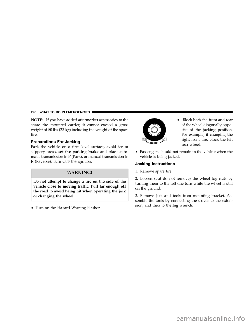
•Block both the front and rear
of the wheel diagonally oppo-
site of the jacking position.
For example, if changing the
right front tire, block the left
rear wheel.
•Passengers should not remain in the vehicle when the
vehicle is being jacked.
Jacking Instructions
1. Remove spare tire.
2. Loosen (but do not remove) the wheel lug nuts by
turning them to the left one turn while the wheel is still
on the ground.
3. Remove jack and tools from mounting bracket. As-
semble the tools by connecting the driver to the exten-
sion, and then to the lug wrench.
296 WHAT TO DO IN EMERGENCIES