2005 JAGUAR S TYPE Rear electronic module
[x] Cancel search: Rear electronic modulePage 9 of 200

DATE OF ISSUE: May 20045
Abbreviations and AcronymsJaguar S-TYPE 2005
The following abbreviations and acronyms are used throughout this Electrical Guide:A/C Air Conditioning
A/CCM Air Conditioning Control Module
ACT SENSOR Air Charge Temperature Sensor
APP SENSOR Accelerator Pedal Position Sensor APP1 Accelerator Pedal Position Sensor Element 1
APP2 Accelerator Pedal Position Sensor Element 2ASC Adaptive Speed Control
AUTO Automatic Transmission B+ Battery Voltage
BANK 1 RH Cylinder Bank
BANK 2 LH Cylinder Bank CAN Controller Area Network
CKP SENSOR Crankshaft Position Sensor CM Control Module
CMP SENSOR / 1 Camshaft Position Sensor / RH Bank
CMP SENSOR / 2 Camshaft Position Sensor / LH Bank D2B D2B Network
DDM Driver Door Module DSC Dynamic Stability Control
DSM Driver Seat Module
ECM Engine Control Module
ECT SENSOR Engine Coolant Temperature Sensor EFT SENSOR Engine Fuel Temperature Sensor
EGR Exhaust Gas Recirculation
EGT SENSOR Exhaust Gas Temperature Sensor
EOT SENSOR Engine Oil Temperature Sensor
EVAP CANISTER CLOSE VALVE Evaporative Emission Canister Close Valve
EVAP CANISTER PURGE VALVE Evaporative Emission Canister Purge Valve FEM Front Electronic Module
FPDB Front Power Distribution Box
FRP SENSOR Fuel Rail Pressure Sensor FTP SENSOR Fuel Tank Pressure Sensor
GPS Global Positioning SystemHID High Intensity Discharge
HO2 SENSOR 1 / 1 Heated Oxygen Sensor – RH Bank / Upstream
HO2 SENSOR 1 / 2 Heated Oxygen Sensor – RH Bank / Downstream
HO2 SENSOR 2 / 1 Heated Oxygen Sensor – LH Bank / Upstream
HO2 SENSOR 2 / 2 Heated Oxygen Sensor – LH Bank / Downstream
IAT SENSOR Intake Air Temperature Sensor IC Instrument Cluster
ICE In-Car Entertainment System
IMT VALVE / 1 Intake Manifold Tuning Valve / Top
IMT VALVE / 2 Intake Manifold Tuning Valve / Bottom IP SENSOR Injection Pressure Sensor
KS / 1 Knock Sensor / RH Bank
KS / 2 Knock Sensor / LH BankLH Left-Hand
LHD Left-Hand Drive
MAF SENSOR Mass Air Flow Sensor MAN Manual Transmission
MAP SENSOR Manifold Absolute Pressure Sensor N/A Normally Aspirated
NAS North American Specification
NCM Navigation Control Module PAM Parking Aid Module
PATS Passive Anti-Theft System
PJB Primary Junction Box
PWM Pulse Width Modulated RCM Restraints Control ModuleREM Rear Electronic Module RH Right-Hand
RHD Right-Hand Drive
ROW Rest of World
RPDB Rear Power Distribution Box SC Supercharged
SCLM Steering Column Lock Module SCM Speed Control ModuleSCP Standard Corporate Protocol Network
Page 11 of 200

DATE OF ISSUE: May 20047
IntroductionJaguar S-TYPE 2005
Electrical Guide Format
This Electrical Guide is made up of two major sections:
the first section, at the front of the book, provides general information for and about the use of the book; model-specific information and illustrations to aid in the understanding of the electrical / electronic systems, as well as the location and
identification of components.
the second section includes the Figures, which are the basis of the book. Each Figure is identified by a Figure Number (e.g. Fig. 01.1) and Title. The page adjacent to the Figure contains data information specific to that Figure.
NOTE: Data pages are not available for inclusion in Provisional versions of the Electrical Guide.
It is recommended that the user read through the front section of the book to develop a familiarity with the layout of the book and with
the system of symbols and abbreviations used. The Table of Contents should help to guide the user.
Vehicle Identification Numbers (VIN)
VIN ranges are presented throughout the book in the following manner:
➝ VIN 123456 indicates ‘up to VIN 123456’; VIN 123456 ➝indicates ‘from VIN 123456 on’.
Electrical System Architecture
Power Supplies
The electrical system is a supply-side switched system. The ignition switch directly carries much of the ignition switched powe r
supply load.
Power supply is provided via three methods:
Direct battery power supply;
Ignition switched power supply;
Switched system power supply.
The ‘Switched System Power Supply’ circuit is controlled via the FEM (Front Electronic Module) and the REM (Rear Electronic
Module). Refer to Fig. 01.6 for circuit activation details.
Fuse Boxes
The electrical harness incorporates two hard-wired power distribution fuse boxes:
the Front Power Distribution Fuse Box, located in the engine compartment;
the Rear Power Distribution Fuse Box, located in the trunk.
A serviceable Primary Junction Fuse Box is located in the front right-hand foot well. All fuses and relays (except the trailer towing
accessory kit) are located in the two fuse boxes.
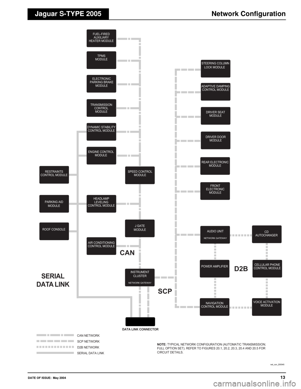
Vehicle Networks
Three different networks are employed:
CAN (Controller Area Network) for high-speed power train communications;
SCP (Standard Corporate Protocol) network for slower speed body systems communications;
D2B (Optical) Network for very high-speed ‘real-time’ audio data transfer.
NOTE: The D2B Network is a fiber optic network with a gateway to the remaining vehicle networks via the Audio Unit. Technician
access to the three networks and the Serial Data Link is via the Data Link Connector.
Ground Studs
Circuit ground connections are made at body studs located throughout the vehicle. There are no separate power and logic groundi ng
systems; however, there are a certain number of components that use unique ground points.
Page 16 of 200

12DATE OF ISSUE: May 2004
Symbols and CodesJaguar S-TYPE 2005
Grounds
On figures where LHD and RHD circuits are combined and the ground designation differs from LHD to RHD, the RHD ground code is
shown in parentheses. If the ground designation is the same for LHD and RHD, only one ground code is used, with no parentheses.
Relays
All relays are located in the Front and Rear Power Distribution Boxes and the Primary Junction Fuse Box. Relays do not have a
separate relay connector (base). All relays use the ISO pin numbering system (1, 2, 3, 4, 5). Each relay is identified by an ‘R’number
unique only to the fuse box in which it is located.
Fuses
All fuses are located in the Front and Rear Power Distribution Boxes and the Primary Junction Fuse Box. Each fuse is identified by
an ‘F’ number unique only to the fuse box in which it is located.
Networks
In most instances, networks are shown as a broken grey line to indicate that there is network communication between the depicte d
control modules. Refer to Fig. 20.1, Fig. 20.2, Fig. 20.3, Fig. 20.4 and Fig. 20.5 for circuit details.
Component Depictions
G30AS
(G26AS)G31BL
EXAMPLE:LHD Vehicles
RHD Vehicles Same for LHD and RHD Vehicles
3
1 5
2
R643
1 5
2
R2
CHANGE-OVER RELAY NORMALLY OPEN RELAY
EXAMPLE:
F19 15A
EXAMPLE:
S
SIP5-2 IP5-1
20.2
20.220.2
IP10-1
IP10-2S
SU Y
U Y
20.2
SCPEXAMPLE:
CONTROL MODULE CONTROL MODULE
MESSAGE(S) MESSAGE(S)
MESSAGE(S)
MESSAGE(S)
COMPLETE COMPONENTS
AND CONTROL MODULES INCOMPLETE COMPONENTS
(EXCEPT CONTROL MODULES) ASSEMBLIES AND
POWER DISTRIBUTION FUSE BOXES COMPONENTS WITH
INTERNAL ELECTRONIC CIRCUIT
EXAMPLE:
Page 17 of 200
DATE OF ISSUE: May 200413
Network ConfigurationJaguar S-TYPE 2005
SERIAL
DATA LINK
ELECTRONIC
PARKING BRAKE MODULE
FUEL-FIREDAUXILIARY
HEATER MODULE
TPMS
MODULE
TRANSMISSION CONTROLMODULE
DYNAMIC STABILITY CONTROL MODULE
ENGINE CONTROL MODULE
SPEED CONTROLMODULE
RESTRAINTS
CONTROL MODULE
PARKING AIDMODULE
ROOF CONSOLE HEADLAMP
LEVELING
CONTROL MODULE
AIR CONDITIONING
CONTROL MODULE
INSTRUMENTCLUSTER
NETWORK GATEWAY
CAN
DATA LINK CONNECTOR
SCP
STEERING COLUMN LOCK MODULE
ADAPTIVE DAMPING CONTROL MODULE
DRIVER SEATMODULE
DRIVER DOOR MODULE
REAR ELECTRONIC MODULE
FRONT
ELECTRONIC MODULE
AUDIO UNIT
NETWORK GATEWAY
POWER AMPLIFIER NAVIGATION
CONTROL MODULED2B
CD
AUTOCHANGER
CELLULAR PHONE
CONTROL MODULE
VOICE ACTIVATION MODULE
J GATE
MODULE
CAN NETWORK
SCP NETWORK
D2B NETWORK
SERIAL DATA LINK NOTE:
TYPICAL NETWORK CONFIGURATION (AUTOMATIC TRANSMISSION;
FULL OPTION SET). REFER TO FIGURES 20.1, 20.2, 20.3, 20.4 AND 20.5 FOR
CIRCUIT DETAILS.
net_con_200045
Page 22 of 200
18DATE OF ISSUE: May 2004
Control Module LocationJaguar S-TYPE 2005
DRIVER SEAT HEATERCONTROL MODULE
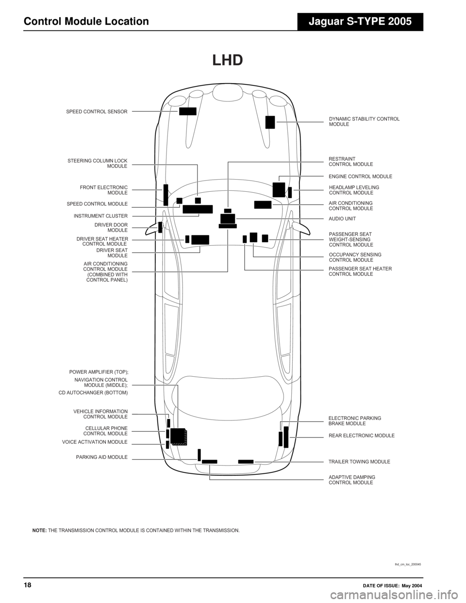
NOTE: THE TRANSMISSION CONTROL MODULE IS CONTAINED WITHIN THE TRANSMISSION.
lhd_cm_loc_200045
LHD
STEERING COLUMN LOCK
MODULE
FRONT ELECTRONIC MODULE
SPEED CONTROL MODULE
INSTRUMENT CLUSTER DRIVER DOORMODULE
DRIVER SEAT MODULE
AIR CONDITIONING
CONTROL MODULE (COMBINED WITH
CONTROL PANEL)
POWER AMPLIFIER (TOP); NAVIGATION CONTROL MODULE (MIDDLE);
CD AUTOCHANGER (BOTTOM)
VEHICLE INFORMATIONCONTROL MODULE
VOICE ACTIVATION MODULE CELLULAR PHONE
CONTROL MODULE
PARKING AID MODULE ELECTRONIC PARKING
BRAKE MODULE
REAR ELECTRONIC MODULE
TRAILER TOWING MODULE ADAPTIVE DAMPING
CONTROL MODULE DYNAMIC STABILITY CONTROL
MODULE
RESTRAINT
CONTROL MODULE
ENGINE CONTROL MODULE HEADLAMP LEVELING
CONTROL MODULE
AIR CONDITIONING
CONTROL MODULE
AUDIO UNIT
PASSENGER SEAT
WEIGHT-SENSING
CONTROL MODULE
OCCUPANCY SENSING
CONTROL MODULE
PASSENGER SEAT HEATER
CONTROL MODULE
SPEED CONTROL SENSOR
Page 23 of 200
DATE OF ISSUE: May 200419
Control Module LocationJaguar S-TYPE 2005
VOICE ACTIVATIONMODULE
CELLULAR PHONE
CONTROL MODULE
VEHICLE INFORMATION
CONTROL MODULE
PARKING AIDMODULE
RESTRAINT CONTROL MODULE
STEERING COLUMN LOCK
MODULE
HEADLAMP LEVELING CONTROL
MODULE SPEED CONTROL MODULE
DYNAMIC STABILITY CONTROL
MODULE
DRIVER SEAT MODULE
DRIVER SEAT HEATER CONTROL
MODULE DRIVER DOOR MODULE
ENGINE CONTROL MODULE
FRONT ELECTRONIC MODULE
AIR CONDITIONING CONTROL MODULE (REMOTE)
PASSENGER SEAT WEIGHT SENSING CONTROL MODULE
OCCUPANCY SENSING CONTROL MODULE
AIR CONDITIONING CONTROL MODULE (COMBINED WITH CONTROL PANEL) PASSENGER SEAT HEATER
CONTROL MODULE
rhd_cm_loc_200045
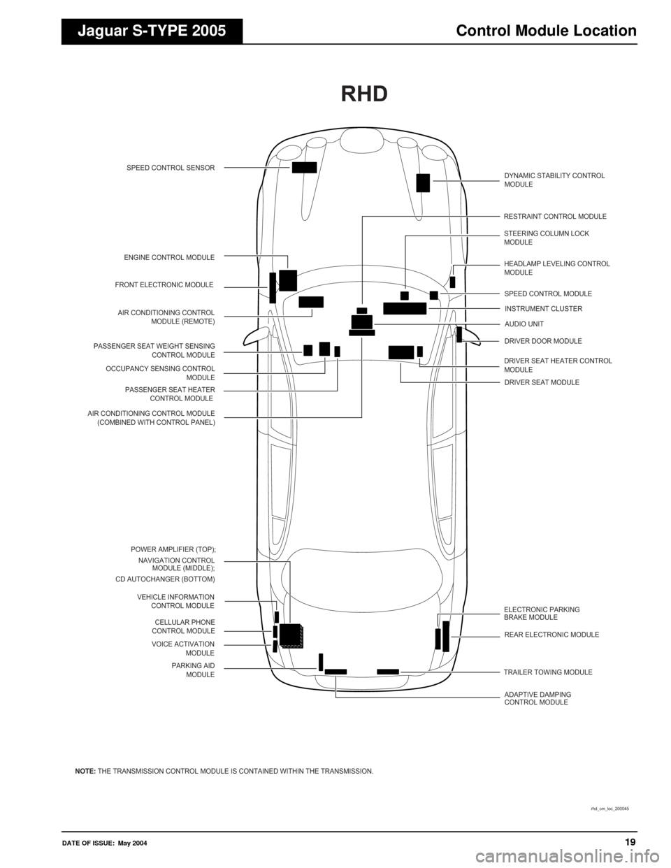
NOTE:THE TRANSMISSION CONTROL MODULE IS CONTAINED WITHIN THE TRANSMISSION. SPEED CONTROL SENSOR
INSTRUMENT CLUSTER
POWER AMPLIFIER (TOP); NAVIGATION CONTROL MODULE (MIDDLE);
CD AUTOCHANGER (BOTTOM)
ELECTRONIC PARKING
BRAKE MODULEREAR ELECTRONIC MODULE
TRAILER TOWING MODULE ADAPTIVE DAMPING
CONTROL MODULEAUDIO UNIT
RHD
Page 29 of 200

DATE OF ISSUE: May 200425
Control Module Pin IdentificationJaguar S-TYPE 2005
REAR ELECTRONIC MODULE
CA102 / BLACK
CA100 / BLACK
CA103 / WHITE
CA101 / BLACK
* LHD - BG; RHD - BO ** LHD - BO; RHD - BG
CA63 / BLACK
CA63CA102
CA100
CA103
CA101
rem_200045
Page 49 of 200

Switched System Power Distribution
Jaguar S-TYPE 2005
Switched System Power Distribution
Fig. 01.6
13 4114
46 80
76 77 92
ll
15 45ll ll SS
81 118EE
Fig .01.1
Fig .01 .2 F
ig .01.3
Fig .01 .4
Fig . 01.5 F
ig . 01.6 F
ig .01 .7
Input
OutputI
O
B
P+Battery VoltagePower Ground Sensor/Signal Supply V
Sensor/Signal Ground Serial and Encoded Data
CAN
+
SCPC
S DD
–
D2B Network2
f01_6_200045
SCP NOTE
:
The switched system power relays are activated by the FEM or the REM
whenever messages are present on the SCP network. After the ignition is switched off,
the relays remain activated until all SCP messages are removed.
86
NG
BOBO
B
BO
B
Y
U
UY
N
20.2
20.2
20.2
20.2
FH59-6
FH59-7
FH59-1
CA101-3
CA102-1
CA102-2 CA101-4
CA102-12 CA156CAR11
CAR9
FH9-21
FH6-9
FH77
FH60-11
LOGIC
LOGIC
SWITCHED SYSTEMPOWER
CONTROL
SWITCHED SYSTEMPOWER
CONTROLB+B+S
O
WU
CA24-10
I
WB
CA24-19
I
P
P
O
S
S
S
FRONT ELECTRONIC MODULE
REAR ELECTRONIC MODULE
87 15
16
N
N
BO
SWITCHED SYSTEM POWER RELAY 1
R2
3
17
18
NR
NR
BO
SWITCHED SYSTEM POWER RELAY 2
R11
3 4
5
2
1
19
20
NW
WU
NW
BO
SWITCHED SYSTEM POWER RELAY 3
R4
3 4
5
2
1 4
5
2
1
CAR10CA61-63 F48 10A CA61-54
CA61-81 F57 10A CA61-72
CA61-83 F59 15A CA61-74 CA61-61 F46 10A CA61-52 CA61-79 F55 10A CA61-70
CAS20BR1-1
CAS5
CA61-77 F53 10A CA61-68 CA61-66 F51 5A CA61-75 CA61-59 F44 10A CA61-50
24
25
NG
WW
WU
NW
NW
CAS43RF34-10
CAS83
CAS37
CA2-9
CA2-3CAS30
FH7-3
FH53-5
FH53-5
FH53-8
FC37-24
CA56-4
FH53-10 FH53-2 FH53-4 FH53-4
FH7-6
FH53-6
FH39-9
FH39-11 FH40-9
FH40-12
FH40-11
FC33-14 FH39-12
FHS29
BF1-1
BF1-5
FHS21
CA2-17 F8 5A
F9 10A
F10 5A
F11 10A
F22 10A F24 5A
F23 10A
F25 10A
F30 10A
F33 10A
BR1-2TT1-1
NR
NG
NR
NR
(1)
(2)(1)
(2)
NW
NW
NR
NR
NR N NR NR
NR
NR NR
NW
NW
NW
NW NR
NR
NR
NR
NR
NW
NW
W WW W
NG
NW
NW
NW NW
NW NW NW
NW
NW
NW
NW
NW
NW
NWN
N OY
NR
NG
NG
NG
NG
N
NG R
NW
NW
WU WU WU
W
W
W
NG
BO
SWITCHED SYSTEM POWER RELAY 4
REAR POWER DISTRIBUTION FUSE BOX
R5
3 4
5
2
1
72S
63S
12.1 08.3
64S
08.3
65S
08.4
66S
05.3
67S
08.3
08.4
08.408.4 08.4
68S
08.3
69S
09.1
70S
09.1 19.1
71S
09.1
08.4
12.2
73S
09.1
74S
09.1
75S
08.3 08.4 08.4
08.4
08.4
76S
08.3
77S
08.3
78S
08.3
79S
08.3
80S
10.2 10.3 12.1 12.2 12.3 14.1
PRIMARY JUNCTION FUSE BOX
NOTE:
FHS21
- Side marker only.
NOTATION:
(1) Non HID headlamp vehicles.
(2) HID headlamp vehicles.
46S
08.1
47S
08.1
48S
08.1 08.2
08.2
08.2
49S
08.1
50S
08.2
51S
08.1 08.2
52S
08.1
53S
08.1
54S
08.1 08.2
08.2
08.2
55S
10.2
56S
02.1
57S
08.1
10.3 12.1 12.2 12.3 14.1
02.2 12.3
08.2
58S
08.1
59S
08.2
60S
05.210.110.212.112.212.313.119.1
61S
09.2
62S
12.1 12.2
CAS21
11.611.6
CAR28CAR29
VARIANT:
All Vehicles
VIN RANGE: All
DATE OF ISSUE: May 2004