Page 2185 of 3419
GW-30
POWER WINDOW SYSTEM
Revision: October 20052005 QX56
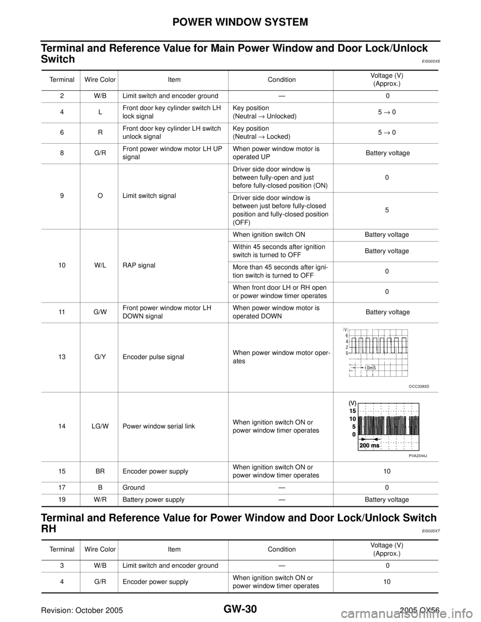
Terminal and Reference Value for Main Power Window and Door Lock/Unlock
Switch
EIS005XS
Terminal and Reference Value for Power Window and Door Lock/Unlock Switch
RH
EIS005XT
Terminal Wire Color Item ConditionVoltage (V)
(Approx.)
2 W/B Limit switch and encoder ground — 0
4LFront door key cylinder switch LH
lock signalKey position
(Neutral → Unlocked)5 → 0
6RFront door key cylinder LH switch
unlock signalKey position
(Neutral → Locked)5 → 0
8G/RFront power window motor LH UP
signalWhen power window motor is
operated UP Battery voltage
9 O Limit switch signalDriver side door window is
between fully-open and just
before fully-closed position (ON)0
Driver side door window is
between just before fully-closed
position and fully-closed position
(OFF)5
10 W/L RAP signalWhen ignition switch ON Battery voltage
Within 45 seconds after ignition
switch is turned to OFFBattery voltage
More than 45 seconds after igni-
tion switch is turned to OFF0
When front door LH or RH open
or power window timer operates0
11 G / WFront power window motor LH
DOWN signalWhen power window motor is
operated DOWN Battery voltage
13 G/Y Encoder pulse signalWhen power window motor oper-
ates
14 LG/W Power window serial linkWhen ignition switch ON or
power window timer operates
15 BR Encoder power supplyWhen ignition switch ON or
power window timer operates10
17 B Ground — 0
19 W/R Battery power supply — Battery voltage
OCC3383D
PIIA2344J
Terminal Wire Color Item ConditionVoltage (V)
(Approx.)
3 W/B Limit switch and encoder ground — 0
4 G/R Encoder power supplyWhen ignition switch ON or
power window timer operates10
Page 2186 of 3419
POWER WINDOW SYSTEM
GW-31
C
D
E
F
G
H
J
K
L
MA
B
GW
Revision: October 20052005 QX56
8LFront power window motor RH UP
signalWhen power window motor is
operated UP Battery voltage
9GFront power window motor RH
DOWN signalWhen power window motor is
operated DOWN Battery voltage
10 W/R Battery power supply — Battery voltage
11 B G r o u n d — 0
12 G/Y Encoder pulse signalWhen power window motor oper-
ates
15 G/W Limit switch signalPassenger side door window is
between fully-open and just
before fully-closed position (ON)0
Passenger side door window is
between just before fully-closed
position and fully-closed position
(OFF)5
16 LG/W Power window serial linkWhen ignition switch is ON or
power window timer operating Terminal Wire Color Item ConditionVoltage (V)
(Approx.)
OCC3383D
PIIA2344J
Page 2187 of 3419
GW-32
POWER WINDOW SYSTEM
Revision: October 20052005 QX56
Terminal and Reference Value for BCMEIS005XU
Terminal Wire Color Item ConditionVoltage (V)
(Approx.)
11 O Ignition switch (ACC or ON) Ignition switch
(ACC or ON position)Battery voltage
12 R/L Front door switch RH signalON (Open) Battery voltage
OFF (Close) 0
22 W/V Power window serial linkWhen ignition switch ON or
power window timer operates
38 W/L Ignition switch (ON or START) Ignition switch
(ON or START position)Battery voltage
47 SB Front door switch LH signalON (Open) Battery voltage
OFF (Close) 0
67 B Ground — 0
68 W/L RAP signalWhen ignition switch ON Battery voltage
Within 45 seconds after ignition
switch is turned to OFFBattery voltage
More than 45 seconds after igni-
tion switch is turned to OFF0
When front door LH or RH is
open or power window timer
operates0
69 W/R Power window power supply — Battery voltage
70 W/B Battery power supply — Battery voltage
PIIA2344J
Page 2188 of 3419
POWER WINDOW SYSTEM
GW-33
C
D
E
F
G
H
J
K
L
MA
B
GW
Revision: October 20052005 QX56
Work FlowEIS005XV
1. Check the symptom and customer's requests.
2. Understand the outline of system. Refer to GW-15, "
System Description" .
3. According to the trouble diagnosis chart, repair or replace the cause of the malfunction.
Refer to GW-35, "
Trouble Diagnoses Symptom Chart" .
4. Does power window system operate normally? Yes, GO TO 5, If No, GO TO 3.
5. Inspection End.
CONSULT-II Function (BCM)EIS005XW
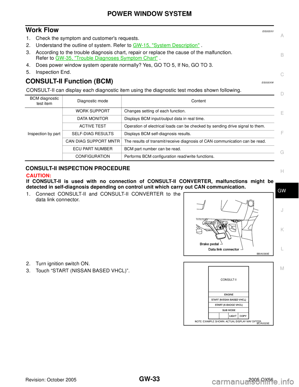
CONSULT-II can display each diagnostic item using the diagnostic test modes shown following.
CONSULT-II INSPECTION PROCEDURE
CAUTION:
If CONSULT-II is used with no connection of CONSULT-II CONVERTER, malfunctions might be
detected in self-diagnosis depending on control unit which carry out CAN communication.
1. Connect CONSULT-II and CONSULT-II CONVERTER to the
data link connector.
2. Turn ignition switch ON.
3. Touch “START (NISSAN BASED VHCL)”.
BCM diagnostic
test itemDiagnostic mode Content
Inspection by partWORK SUPPORT Changes setting of each function.
DATA MONITOR Displays BCM input/output data in real time.
ACTIVE TEST Operation of electrical loads can be checked by sending drive signal to them.
SELF-DIAG RESULTS Displays BCM self-diagnosis results.
CAN DIAG SUPPORT MNTR The results of transmit/receive diagnosis of CAN communication can be read.
ECU PART NUMBER BCM part number can be read.
CONFIGURATION Performs BCM configuration read/write functions.
BBIA0369E
BCIA0029E
Page 2189 of 3419
GW-34
POWER WINDOW SYSTEM
Revision: October 20052005 QX56
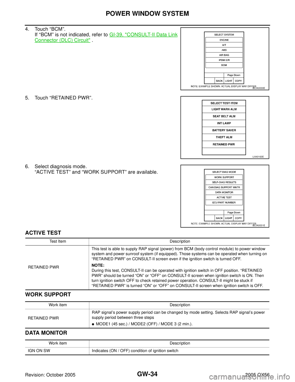
4. Touch “BCM”.
If “BCM” is not indicated, refer to GI-39, "
CONSULT-II Data Link
Connector (DLC) Circuit" .
5. Touch “RETAINED PWR”.
6. Select diagnosis mode.
“ACTIVE TEST” and “WORK SUPPORT” are available.
ACTIVE TEST
WORK SUPPORT
DATA MONITOR
BCIA0030E
LIIA0163E
BCIA0031E
Test Item Description
RETAINED PWRThis test is able to supply RAP signal (power) from BCM (body control module) to power window
system and power sunroof system (if equipped). Those systems can be operated when turning on
“RETAINED PWR” on CONSULT-II screen even if the ignition switch is turned OFF.
NOTE:
During this test, CONSULT-II can be operated with ignition switch in OFF position. “RETAINED
PWR” should be turned “ON” or “OFF” on CONSULT-II screen when ignition switch is ON. Then
turn ignition switch OFF to check retained power operation. CONSULT-II might be stuck if
“RETAINED PWR” is turned “ON” or “OFF” on CONSULT-II screen when ignition switch is OFF.
Work item Description
RETAINED PWRRAP signal’s power supply period can be changed by mode setting. Selects RAP signal’s power
supply period between three steps
�MODE1 (45 sec.) / MODE2 (OFF) / MODE 3 (2 min.).
Work item Description
IGN ON SW Indicates (ON / OFF) condition of ignition switch
Page 2192 of 3419
POWER WINDOW SYSTEM
GW-37
C
D
E
F
G
H
J
K
L
MA
B
GW
Revision: October 20052005 QX56
BCM Power Supply and Ground Circuit CheckEIS005XY
1. CHECK FUSE AND FUSIBLE LINK
�Check 10A fuse (No. 4, located in the fuse block (J/B)]
�Check 10A fuse (No. 59, located in the fuse and relay box)
�Check 50A fusible link (letter f located in the fuse and fusible link box)
NOTE:
Refer to GW-15, "
Component Parts and Harness Connector Location" .
OK or NG
OK >> GO TO 2.
NG >> If fuse is blown, be sure to eliminate cause of malfunction before installing new fuse. Refer to PG-
3, "PRECAUTIONS" .
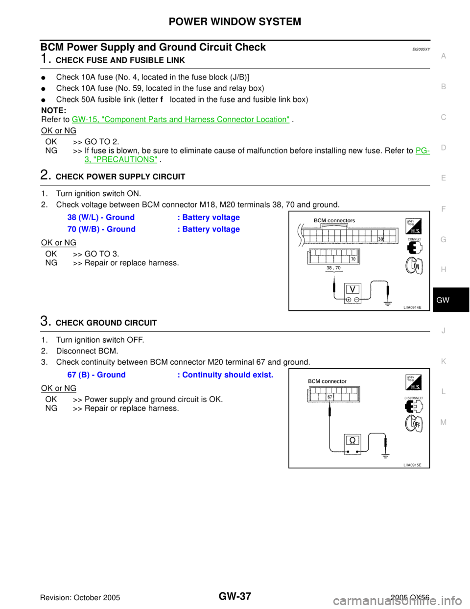
2. CHECK POWER SUPPLY CIRCUIT
1. Turn ignition switch ON.
2. Check voltage between BCM connector M18, M20 terminals 38, 70 and ground.
OK or NG
OK >> GO TO 3.
NG >> Repair or replace harness.
3. CHECK GROUND CIRCUIT
1. Turn ignition switch OFF.
2. Disconnect BCM.
3. Check continuity between BCM connector M20 terminal 67 and ground.
OK or NG
OK >> Power supply and ground circuit is OK.
NG >> Repair or replace harness.38 (W/L) - Ground : Battery voltage
70 (W/B) - Ground : Battery voltage
LIIA0914E
67 (B) - Ground : Continuity should exist.
LIIA0915E
Page 2193 of 3419
GW-38
POWER WINDOW SYSTEM
Revision: October 20052005 QX56
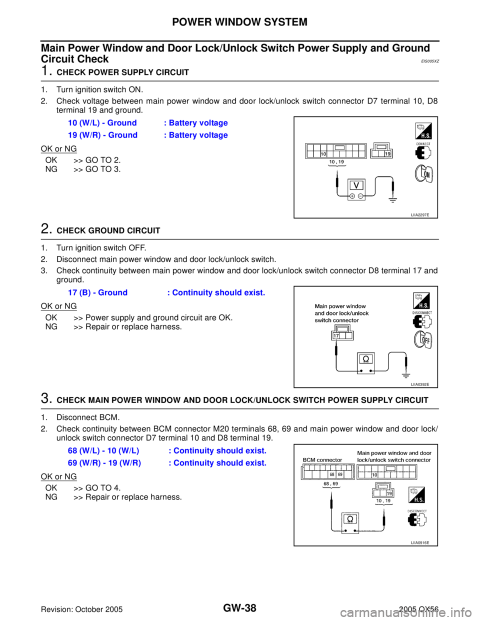
Main Power Window and Door Lock/Unlock Switch Power Supply and Ground
Circuit Check
EIS005XZ
1. CHECK POWER SUPPLY CIRCUIT
1. Turn ignition switch ON.
2. Check voltage between main power window and door lock/unlock switch connector D7 terminal 10, D8
terminal 19 and ground.
OK or NG
OK >> GO TO 2.
NG >> GO TO 3.
2. CHECK GROUND CIRCUIT
1. Turn ignition switch OFF.
2. Disconnect main power window and door lock/unlock switch.
3. Check continuity between main power window and door lock/unlock switch connector D8 terminal 17 and
ground.
OK or NG
OK >> Power supply and ground circuit are OK.
NG >> Repair or replace harness.
3. CHECK MAIN POWER WINDOW AND DOOR LOCK/UNLOCK SWITCH POWER SUPPLY CIRCUIT
1. Disconnect BCM.
2. Check continuity between BCM connector M20 terminals 68, 69 and main power window and door lock/
unlock switch connector D7 terminal 10 and D8 terminal 19.
OK or NG
OK >> GO TO 4.
NG >> Repair or replace harness.10 (W/L) - Ground : Battery voltage
19 (W/R) - Ground : Battery voltage
LIIA2297E
17 (B) - Ground : Continuity should exist.
LIIA0392E
68 (W/L) - 10 (W/L) : Continuity should exist.
69 (W/R) - 19 (W/R) : Continuity should exist.
LIIA0916E
Page 2194 of 3419
POWER WINDOW SYSTEM
GW-39
C
D
E
F
G
H
J
K
L
MA
B
GW
Revision: October 20052005 QX56
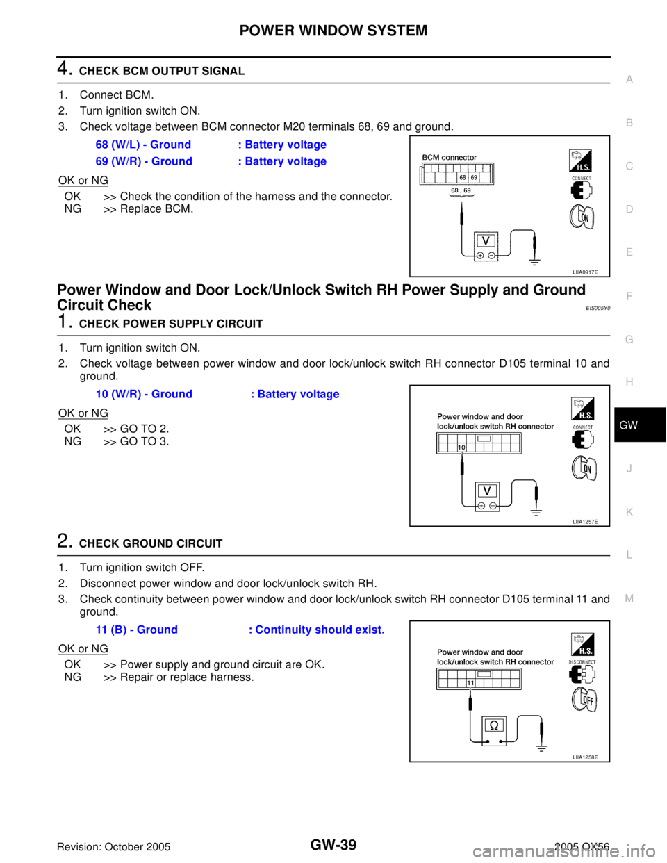
4. CHECK BCM OUTPUT SIGNAL
1. Connect BCM.
2. Turn ignition switch ON.
3. Check voltage between BCM connector M20 terminals 68, 69 and ground.
OK or NG
OK >> Check the condition of the harness and the connector.
NG >> Replace BCM.
Power Window and Door Lock/Unlock Switch RH Power Supply and Ground
Circuit Check
EIS005Y0
1. CHECK POWER SUPPLY CIRCUIT
1. Turn ignition switch ON.
2. Check voltage between power window and door lock/unlock switch RH connector D105 terminal 10 and
ground.
OK or NG
OK >> GO TO 2.
NG >> GO TO 3.
2. CHECK GROUND CIRCUIT
1. Turn ignition switch OFF.
2. Disconnect power window and door lock/unlock switch RH.
3. Check continuity between power window and door lock/unlock switch RH connector D105 terminal 11 and
ground.
OK or NG
OK >> Power supply and ground circuit are OK.
NG >> Repair or replace harness.68 (W/L) - Ground : Battery voltage
69 (W/R) - Ground : Battery voltage
LIIA0917E
10 (W/R) - Ground : Battery voltage
LIIA1257E
11 (B) - Ground : Continuity should exist.
LIIA1258E