Page 2889 of 3419

RSU-14
TROUBLE DIAGNOSIS
Revision: October 20052005 QX56
6. Select the required operation from the "SELECT DIAG MODE"
screen.
For further information, see the CONSULT-II Operation Manual.
WORK SUPPORT
Operation Procedure
1. Touch “AIR LEVELIZER” on “SELECT SYSTEM” screen.
2. Touch “WORK SUPPORT” on “SELECT DIAG MODE” screen.
3. Touch item on “SELECT WORK ITEM” screen.
4. Touch “START”.
5. The setting will be changed and “ADJUSTMENT COMPLETE” will be displayed.
6. Touch “END”.
Display Item List
SELF-DIAGNOSIS
Description
If an error is detected in the system, perform self-diagnosis as follows:
Operation Procedure
1. Turn ignition switch OFF.
2. Connect CONSULT-II and CONSULT-II CONVERTER to the data link connector.
CAUTION:
If CONSULT-II is used with no connection of CONSULT-II CONVERTER, malfunctions might be
detected in self-diagnosis depending on control unit which carries out CAN communication.
3. Turn ignition switch ON.
4. After stopping the vehicle, with the engine running, touch "START (NISSAN BASED VHCL)", "AIR LEV-
ELIZER", "SELF-DIAG RESULTS" in order on the CONSULT-II screen.
CAUTION:
If "START (NISSAN BASED VHCL)" is touched immediately after starting the engine or turning on
the ignition switch, "AIR LEVELIZER" might not be displayed in the "SELECT SYSTEM" screen. In
this case, repeat the operation from step 1.
5. The self-diagnostic results are displayed. (If necessary, the self-diagnostic results can be printed out by
touching "COPY".)
�When "NO DTC IS DETECTED" is displayed, check the CK SUSP indicator lamp.
6. Conduct the appropriate inspection from the display item list, and repair or replace the malfunctioning
component.
7. Start and run the vehicle for approximately 1 minute.
8. Turn ignition switch OFF to prepare for erasing the memory.
9. Start the engine and touch "START (NISSAN BASED VHCL)", "AIR LEVELIZER", "SELF-DIAG
RESULTS", "ERASE" in order on the CONSULT-II screen to erase the error memory.
If "AIR LEVELIZER" is not indicated, go to GI-39, "
CONSULT-II Data Link Connector (DLC) Circuit" .
BCIA0031E
Item Description
STANDARD HEIGHT LEVEL This mode allows the vehicle height to be set to vehicle height specification within tolerance.
ADJUST HEIGHT INI The initialization value and flag can be set in the suspension control unit in this mode.
CLEAR HEIGHT INI This mode clears the initialization flag and value in the suspension control unit.
Page 2890 of 3419

TROUBLE DIAGNOSIS
RSU-15
C
D
F
G
H
I
J
K
L
MA
B
RSU
Revision: October 20052005 QX56
CAUTION:
If the error memory is not erased, re-conduct the operation from step 7.
10. For the final inspection, start and run the vehicle for approximately 1 minute and confirm that the CK
SUSP indicator lamp is off.
Display Item List
DATA MONITOR
Operation Procedure
1. After turning OFF the ignition switch, connect CONSULT-II and the CONSULT-II CONVERTER to the data
link connector.
CAUTION:
If CONSULT-II is used with no connection of CONSULT-II CONVERTER, malfunctions might be
detected in self-diagnosis depending on control unit which carries out CAN communication.
2. Touch "START (NISSAN BASED VHCL)", "AIR LEVELIZER", "DATA MONITOR" in order on the CON-
SULT-II screen.
If "AIR LEVELIZER" is not indicated, go to GI-39, "
CONSULT-II Data Link Connector (DLC) Circuit" .
CAUTION:
When "START (NISSAN BASED VHCL)" is touched immediately after starting the engine or turning
on the ignition switch, "AIR LEVELIZER" might not be displayed in the "SELECT SYSTEM" screen.
In this case, repeat the operation from step 2.
3. Return to the "SELECT MONITOR ITEM" screen, and touch "ALL SIGNALS" or "SELECTION FROM
MENU". Refer to the following information.
4. When "START" is touched, the data monitor screen is displayed.
Self-diagnostic item Malfunction detecting condition Check system
Vehicle height sensor
[C1801]Vehicle height sensor voltage is less than 0.2V or greater than
4.8V for more than 60 seconds.Refer to RSU-17, "
Height
Sensor System Inspection" .
Compressor relay
[C1802]1. Driving transistor for compressor relay is off and monitor volt-
age continues high level for more than 10 seconds.
2. Driving transistor for compressor relay is on and monitor volt-
age continues low level for more than 5 seconds.Refer to RSU-20, "
Compres-
sor Motor, Compressor
Motor Relay and Circuit
Inspection" .
Exhaust solenoid
[C1803]1. Driving transistor for exhaust solenoid is off and monitor volt-
age continues high level for more than 10 seconds.
2. Driving transistor for exhaust solenoid is on and monitor volt-
age continues low level for more than 5 seconds.Refer to RSU-19, "
Exhaust
Valve Solenoid System
Inspection" .
Vehicle height adjusting trouble
(compressor)
[C1804]Continuous compressor relay ON time is more than 120 sec-
onds.Refer to RSU-20, "
Compres-
sor Motor, Compressor
Motor Relay and Circuit
Inspection" .
Vehicle height adjusting trouble
(exhaust solenoid)
[C1805]Continuous exhaust solenoid ON time is more than 120 seconds.Refer to RSU-19, "
Exhaust
Valve Solenoid System
Inspection" .
Vehicle height sensor locking trou-
ble
[C1806]Output sensor voltage variation ±0.02V is more than 100 hour
when vehicle height range is normal.Refer to RSU-17, "
Height
Sensor System Inspection" .
Sensor 5V trouble
[C1807]Sensor reference voltage is less than 0.8V or more than 6V for
20 seconds.Refer to RSU-17, "
Height
Sensor System Inspection" .
Integral time trouble by supplying
air
[C1808]Integral discontinuous time on the compressor is more than 180
seconds.Refer to RSU-20, "
Compres-
sor Motor, Compressor
Motor Relay and Circuit
Inspection" .
Page 2891 of 3419

RSU-16
TROUBLE DIAGNOSIS
Revision: October 20052005 QX56
Display Item List
X: Applicable
–: Not applicable
ACTIVE TEST
CAUTION:
�Do not perform active test while driving.
Operation Procedure
1. Connect the CONSULT-II and CONSULT-II CONVERTER to the data link connector and start the engine.
CAUTION:
If CONSULT-II is used with no connection of CONSULT-II CONVERTER, malfunctions might be
detected in self-diagnosis depending on control unit which carries out CAN communication.
2. Touch "START (NISSAN BASED VHCL)" on the display screen.
3. Touch "AIR LEVELIZER".
If "AIR LEVELIZER" is not indicated, go to GI-39, "
CONSULT-II Data Link Connector (DLC) Circuit" .
4. Touch "ACTIVE TEST".
5. The "SELECT TEST ITEM" screen is displayed.
6. Touch necessary test item.
7. With the "MAIN SIGNALS" display highlighted, touch "START".
8. The active test screen will be displayed.
Display Item List
CAUTION:
The "COMPRESSOR" active test will remain ON until it is turned off using CONSULT-II. Allowing the
compressor to run for an extended period of time may cause damage to air suspension system com-
ponents due to excessive pressure in the air suspension system.
NOTE:
�"TEST IS STOPPED" is displayed approximately 10 seconds after operation starts for all active test items
except "COMPRESSOR".
�After "TEST IS STOPPED" is displayed, to perform test again, repeat Step 6.
Te s t I t e mData monitor item selection
ALL
SIGNALSSELECTION
FROM MENU
HEIGT SENXX
HEIGT CALCXX
SEN FIX TIMEXX
HEIGT INI VALXX
COMPRESSOR X X
EXH SOLENOID X X
ACG LXX
Test Item Description
COMPRESSOROFF/ON
EXHAUST SOLENOIDOFF/ON
WARNING LAMPOFF/ON
Page 2899 of 3419
RSU-24
TROUBLE DIAGNOSES FOR SYMPTOMS
Revision: October 20052005 QX56
4. CHECK GENERATOR SIGNAL INPUT
1. Start the engine.
2. Check voltage between suspension control unit connector B3
terminal 15 (BR/W) and ground.
OK or NG
OK >> Replace the suspension control unit. Refer to RSU-46,
"CONTROL UNIT" .
NG >> Repair the circuit.
CK SUSP Indicator Lamp Stays On When Ignition Switch Is Turned OnEES001HE
1. CARRY OUT SELF-DIAGNOSIS
Carry out self-diagnosis. Refer to RSU-14, "
SELF-DIAGNOSIS" .
Are malfunctions detected in self-diagnosis?
YES >> Refer to RSU-16, "Display Item List" .
NO >> Refer to DI-30, "
WARNING LAMPS" . Voltage : Approx. 12V
WEIA0071E
Page 2908 of 3419

REAR SUSPENSION MEMBER
RSU-33
C
D
F
G
H
I
J
K
L
MA
B
RSU
Revision: October 20052005 QX56
INSTALLATION
Installation is in the reverse order of removal.
�When raising the rear suspension member assembly, use the
locating pins to align the rear suspension member to the vehicle
body.
�When installing the upper and lower rubber seats for the rear
coil springs, the arrow embossed on the rubber seats must point
out toward the wheel and tire assembly.
�To connect the rear load leveling air suspension hoses, the lock
ring must be fully seated in the fitting. Insert the hose “B” into the
lock ring “A” until the lock ring “A” is touching the hose “B” as
shown. Pull on the hose to check that it is securely inserted.
�Perform the final tightening of the nuts and bolts for the links (rubber bushing) under unladen condition
(unladen condition means that the fuel tank, engine coolant and lubricants are at the full specification, and
the spare tire, jack, hand tools, and mats are in their designated positions) with the tires on level ground.
�Check the wheel alignment. Refer to RSU-47, "Wheel Alignment" .
LEIA0083E
LEIA0076E
LEIA0078E
Page 2911 of 3419
RSU-36
SUSPENSION ARM
Revision: October 20052005 QX56
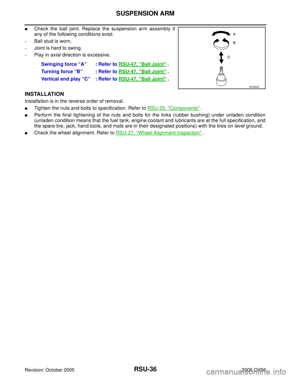
�Check the ball joint. Replace the suspension arm assembly if
any of the following conditions exist:
–Ball stud is worn.
–Joint is hard to swing.
–Play in axial direction is excessive.
INSTALLATION
Installation is in the reverse order of removal.
�Tighten the nuts and bolts to specification. Refer to RSU-25, "Components" .
�Perform the final tightening of the nuts and bolts for the links (rubber bushing) under unladen condition
(unladen condition means that the fuel tank, engine coolant and lubricants are at the full specification, and
the spare tire, jack, hand tools, and mats are in their designated positions) with the tires on level ground.
�Check the wheel alignment. Refer to RSU-27, "Wheel Alignment Inspection" . Swinging force “A” : Refer to RSU-47, "
Ball Joint" .
Turning force “B” : Refer to RSU-47, "
Ball Joint" .
Vertical end play “C” : Refer to RSU-47, "
Ball Joint" .
SFA858A
Page 2913 of 3419
RSU-38
FRONT LOWER LINK
Revision: October 20052005 QX56
INSTALLATION
Installation is in the reverse order of removal.
�Tighten the nuts and bolts to specification. Refer to RSU-25, "Components" .
�Perform the final tightening of the nuts and bolts for the links (rubber bushing) under unladen condition
(unladen condition means that the fuel tank, engine coolant and lubricants are at the full specification, and
the spare tire, jack, hand tools, and mats are in their designated positions) with the tires on level ground.
�Check the wheel alignment. Refer to RSU-27, "Wheel Alignment Inspection" .
Page 2920 of 3419
HEIGHT SENSOR
RSU-45
C
D
F
G
H
I
J
K
L
MA
B
RSU
Revision: October 20052005 QX56
INSTALLATION
Installation is in the reverse order of removal.
1. Start the engine.
2. Use CONSULT-II to perform "STANDARD HEIGHT LEVEL" work support function.
3. Using data monitor of CONSULT-II, verify "HEIGT CALC" is at 0 mm.
4. Check the vehicle height. Refer to RSU-48, "
Wheelarch Height (Unladen*1 )" . If vehicle height is not
within ± 10 mm (0 ± 0.39 in) of the specification, perform the initialization procedure. Refer to RSU-46,
"Initialization Procedure" .