Page 314 of 3419
AIR BREATHER HOSE
AT-243
D
E
F
G
H
I
J
K
L
MA
B
AT
Revision: October 20052005 QX56
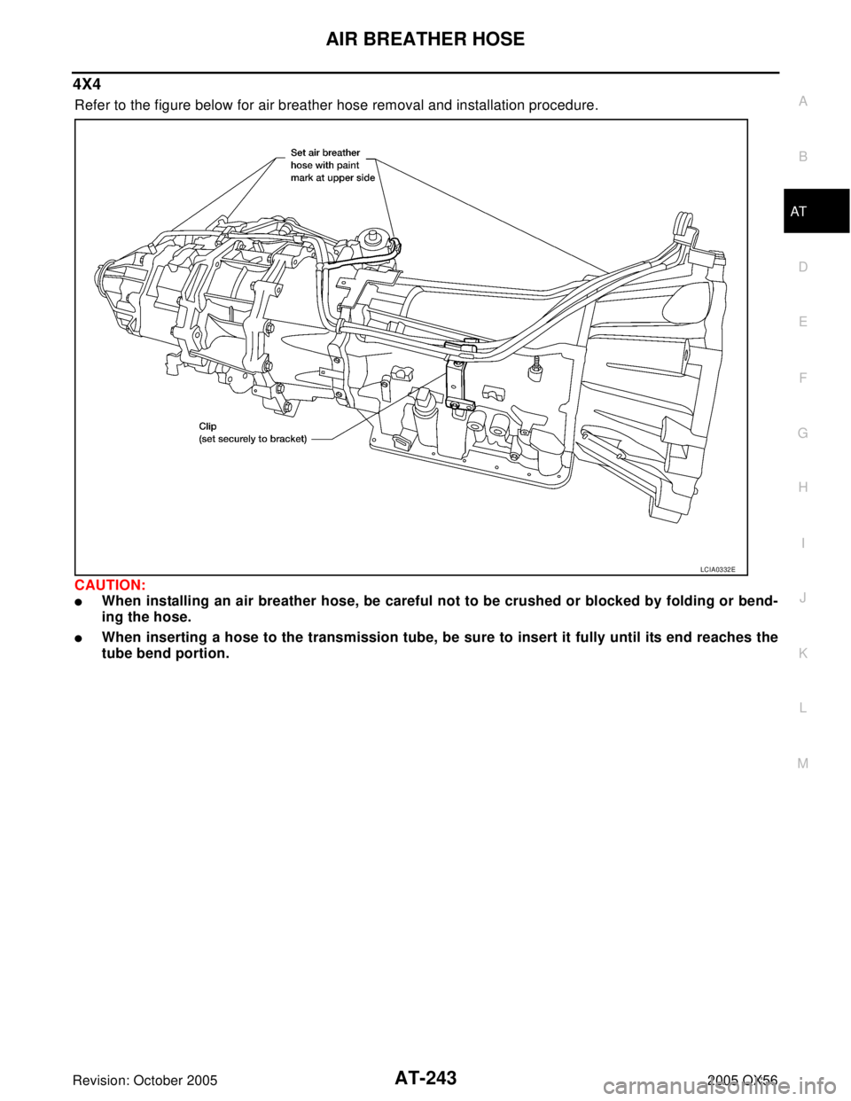
4X4
Refer to the figure below for air breather hose removal and installation procedure.
CAUTION:
�When installing an air breather hose, be careful not to be crushed or blocked by folding or bend-
ing the hose.
�When inserting a hose to the transmission tube, be sure to insert it fully until its end reaches the
tube bend portion.
LCIA0332E
Page 316 of 3419
 from A/T assembly.
9. Remove fluid cooler tube.
10. Remove dust cover")
TRANSMISSION ASSEMBLY
AT-245
D
E
F
G
H
I
J
K
L
MA
B
AT
Revision: October 20052005 QX56
8. Remove crankshaft position sensor (POS) from A/T assembly.
9. Remove fluid cooler tube.
10. Remove dust cover from converter housing part.
11. Secure drive plate using Tool then remove drive plate to torque
converter bolts.
CAUTION:
When turning crankshaft, turn it clockwise as viewed from
the front of the engine.
NOTE:
Tool must be removed and drive plate turned to access all drive
plate to torque converter bolts.
12. Support A/T assembly with a transmission jack.
CAUTION:
When setting the transmission jack, be careful not to allow it to collide against the drain plug.
13. Remove cross member with power tool.
14. Remove air breather hose. Refer to AT-242, "
Removal and Installation" .
15. Disconnect A/T assembly connector.
16. Remove A/T fluid indicator pipe from A/T assembly.
17. Plug up openings such as the A/T fluid indicator pipe hole, etc.
18. Remove the A/T assembly to engine bolts with power tool.
19. Remove A/T assembly from vehicle using Tool and a transmis-
sion jack.
CAUTION:
�Secure torque converter to prevent it from dropping.
�Secure A/T assembly to a transmission jack.
INSPECTION
Installation and Inspection of Torque Converter
�After inserting a torque converter to a transmission, be sure to
check dimension A to ensure it is within the reference value
limit.
LCIA0334E
Tool number : — (J-47245)
LCIA0335E
SCIA0499E
Dimension A : 24.0 mm (0.94 in) or more
SAT0 1 7B
Page 317 of 3419

AT-246
TRANSMISSION ASSEMBLY
Revision: October 20052005 QX56
INSTALLATION
Installation of the remaining components is in the reverse order of the removal, while paying attention to the
following:
�When installing transmission to the engine, attach the bolts as shown.
NOTE:
*: No.2 bolt also secures air breather vent.
�Align the positions of bolts for drive plate with those of the torque
converter, and temporarily tighten the bolts. Then, tighten the
bolts with the specified torque, using Tool to secure drive plate.
CAUTION:
�When turning crankshaft, turn it clockwise as viewed from
the front of the engine.
�After converter is installed to drive plate, rotate crankshaft
several turns and check to be sure that transmission
rotates freely without binding.
�Install crankshaft position sensor (POS).
�After completing installation, check fluid leakage, fluid level, and the positions of A/T. Refer to MA-22,
"Checking A/T Fluid" , AT - 2 2 8 , "Checking of A/T Position" , AT-228, "Adjustment of A/T Position" . Transmission to
engine bolts: 113 N·m (12 kg-m, 83 ft-lb)
LCIA0371E
Tool number : — (J-47245)
LCIA0335E
Page 319 of 3419
 from A/T assembly.
9. Disconnect A/T fluid cooler tube from A/T assembly.
10. Remove dust cover")
AT-248
TRANSMISSION ASSEMBLY
Revision: October 20052005 QX56
8. Remove crankshaft position sensor (POS) from A/T assembly.
9. Disconnect A/T fluid cooler tube from A/T assembly.
10. Remove dust cover from converter housing part.
11. Secure drive plate using Tool then remove drive plate to torque
converter bolts.
CAUTION:
When turning crankshaft, turn it clockwise as viewed from
the front of the engine.
NOTE:
Tool must be removed and drive plate turned to access all drive
plate to torque converter bolts.
12. Support A/T assembly with a transmission jack.
CAUTION:
When setting the transmission jack, be careful not to allow it to collide against the drain plug.
13. Remove cross member with power tool.
14. Tilt the transmission slightly to keep the clearance between body and transmission, and then disconnect
air breather hose from A/T fluid indicator pipe. Refer to AT-244, "
REMOVAL" .
15. Disconnect A/T assembly connector and transfer unit connector.
16. Remove A/T fluid indicator pipe.
17. Plug up openings such as the fluid charging pipe hole, etc.
18. Remove A/T assembly to engine bolts with power tool.
19. Remove A/T assembly with transfer from vehicle, using Tool.
CAUTION:
�Secure torque converter to prevent it from dropping.
�Secure A/T assembly to a transmission jack.
NOTE:
The actual special service tool may differ from tool shown.
20. Remove transfer from A/T assembly. Refer to TF-143,
"REMOVAL" .
INSPECTION
Installation and Inspection of Torque Converter
�After inserting a torque converter to a transmission, be sure to
check dimension A to ensure it is within the reference value
limit.
LCIA0334E
Tool number : — (J-47245)
Tool number : — (J-47002)
LCIA0335E
SCIA2203E
Dimension A : 24.0 mm (0.94 in) or more
SAT0 1 7B
Page 320 of 3419

TRANSMISSION ASSEMBLY
AT-249
D
E
F
G
H
I
J
K
L
MA
B
AT
Revision: October 20052005 QX56
INSTALLATION
Installation of the remaining components is in the reverse order of removal, while paying attention to the fol-
lowing:
�When installing transmission to the engine, attach the bolts as shown.
NOTE:
*: No.2 bolt also secures air breather vent.
�Align the positions of bolts for drive plate with those of the torque
converter, and temporarily tighten the bolts. Then, tighten the
bolts with the specified torque, using Tool to secure drive plate.
CAUTION:
�When turning crankshaft, turn it clockwise as viewed from
the front of the engine.
�After converter is installed to drive plate, rotate crankshaft
several turns and check to be sure that transmission
rotates freely without binding.
�Install crankshaft position sensor (POS).
�After completing installation, check fluid leakage, fluid level, and the positions of A/T. Refer to MA-22,
"Checking A/T Fluid" , AT-228, "Checking of A/T Position" , AT- 2 2 8 , "Adjustment of A/T Position" . Transmission to engine
bolts: 113 N·m (12 kg-m, 83 ft-lb)
LCIA0371E
Tool number : — (J-47245)
LCIA0335E
Page 333 of 3419
AT-262
DISASSEMBLY
Revision: October 20052005 QX56
DISASSEMBLYPFP:31020
DisassemblyECS00CL5
CAUTION:
Do not disassemble parts behind Drum Support. Refer to AT-1 6, "
Cross-Sectional View (2WD models)"
or AT-17, "Cross-Sectional View (4WD models)" .
1. Drain ATF through drain plug.
2. Remove torque converter by holding it firmly and turing while
pulling straight out.
3. Check torque converter one-way clutch using check tool as
shown.
a. Insert check tool into the groove of bearing support built into
one-way clutch outer race.
b. When fixing bearing support with check tool, rotate one- way
clutch spline using screwdriver.
c. Check that inner race rotates clockwise only. If not, replace
torque converter assembly.
4. Remove converter housing from transmission case.
CAUTION:
Be careful not to scratch converter housing.
SCIA5010E
SCIA3171E
SCIA5171E
Page 336 of 3419
DISASSEMBLY
AT-265
D
E
F
G
H
I
J
K
L
MA
B
AT
Revision: October 20052005 QX56
14. Loosen lock nut and remove band servo anchor end pin from
transmission case.
15. Remove brake band from transmission case.
�To prevent brake linings from cracking or peeling, do not
stretch the flexible band unnecessarily. When removing
the brake band, always secure it with a clip as shown in
the figure at left.
Leave the clip in position after removing the brake band.
�Check brake band facing for damage, cracks, wear or
burns.
16. Remove mid carrier assembly and rear carrier assembly as a
unit.
SCIA5016E
SCIA5345E
SAT6 5 5
SCIA5344E
Page 355 of 3419
AT-284
REPAIR FOR COMPONENT PARTS
Revision: October 20052005 QX56
b. Check 3rd one-way clutch for correct locking and unlocking
directions.
CAUTION:
If not as shown in illustration, check installation direction of
3rd one-way clutch.
Front Carrier, Input Clutch, Rear Internal GearECS00CL8
COMPONENTS
SCIA3131E
SCIA5244E
\"")

