Page 1802 of 3419

DTC P2138 APP SENSOR
EC-611
C
D
E
F
G
H
I
J
K
L
MA
EC
Revision: October 20052005 QX56
DTC P2138 APP SENSORPFP:18002
Component DescriptionUBS00HCS
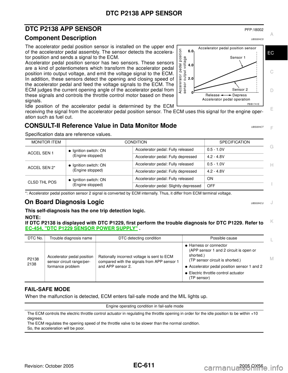
The accelerator pedal position sensor is installed on the upper end
of the accelerator pedal assembly. The sensor detects the accelera-
tor position and sends a signal to the ECM.
Accelerator pedal position sensor has two sensors. These sensors
are a kind of potentiometers which transform the accelerator pedal
position into output voltage, and emit the voltage signal to the ECM.
In addition, these sensors detect the opening and closing speed of
the accelerator pedal and feed the voltage signals to the ECM. The
ECM judges the current opening angle of the accelerator pedal from
these signals and controls the throttle control motor based on these
signals.
Idle position of the accelerator pedal is determined by the ECM
receiving the signal from the accelerator pedal position sensor. The ECM uses this signal for the engine oper-
ation such as fuel cut.
CONSULT-II Reference Value in Data Monitor ModeUBS00HCT
Specification data are reference values.
*: Accelerator pedal position sensor 2 signal is converted by ECM internally. Thus, it differ from ECM terminal voltage.
On Board Diagnosis LogicUBS00HCU
This self-diagnosis has the one trip detection logic.
NOTE:
If DTC P2138 is displayed with DTC P1229, first perform the trouble diagnosis for DTC P1229. Refer to
EC-454, "
DTC P1229 SENSOR POWER SUPPLY" .
FAIL-SAFE MODE
When the malfunction is detected, ECM enters fail-safe mode and the MIL lights up.
PBIB1741E
MONITOR ITEM CONDITION SPECIFICATION
ACCEL SEN 1
�Ignition switch: ON
(Engine stopped)Accelerator pedal: Fully released 0.5 - 1.0V
Accelerator pedal: Fully depressed 4.2 - 4.8V
ACCEL SEN 2*
�Ignition switch: ON
(Engine stopped)Accelerator pedal: Fully released 0.5 - 1.0V
Accelerator pedal: Fully depressed 4.2 - 4.8V
CLSD THL POS
�Ignition switch: ON
(Engine stopped)Accelerator pedal: Fully released ON
Accelerator pedal: Slightly depressed OFF
DTC No. Trouble diagnosis name DTC detecting condition Possible cause
P2138
2138Accelerator pedal position
sensor circuit range/per-
formance problemRationally incorrect voltage is sent to ECM
compared with the signals from APP sensor 1
and APP sensor 2.
�Harness or connector
(APP sensor 1 and 2 circuit is open or
shorted.)
(TP sensor circuit is shorted.)
�Accelerator pedal position sensor 1 and 2
�Electric throttle control actuator
(TP sensor)
Engine operating condition in fail-safe mode
The ECM controls the electric throttle control actuator in regulating the throttle opening in order for the idle position to be within +10
degrees.
The ECM regulates the opening speed of the throttle valve to be slower than the normal condition.
So, the acceleration will be poor.
Page 1803 of 3419
EC-612Revision: October 2005
DTC P2138 APP SENSOR
2005 QX56
DTC Confirmation ProcedureUBS00HCV
NOTE:
If DTC Confirmation Procedure has been previously conducted, always turn ignition switch OFF and wait at
least 10 seconds before conducting the next test.
TESTING CONDITION:
Before performing the following procedure, confirm that battery voltage is more than 8V at idle.
WITH CONSULT-II
1. Turn ignition switch ON.
2. Select “DATA MONITOR” mode with CONSULT-II.
3. Start engine and let it idle for 1 second.
4. If DTC is detected, go to EC-614, "
Diagnostic Procedure" .
WITH GST
Follow the procedure “WITH CONSULT-II” above.
SEF 0 58 Y
Page 1805 of 3419

EC-614Revision: October 2005
DTC P2138 APP SENSOR
2005 QX56
Specification data are reference values and are measured between each terminal and ground.
CAUTION:
Do not use ECM ground terminals when measuring input/output voltage. Doing so may result in dam-
age to the ECM's transistor. Use a ground other than ECM terminals, such as the ground.
Diagnostic ProcedureUBS00HCX
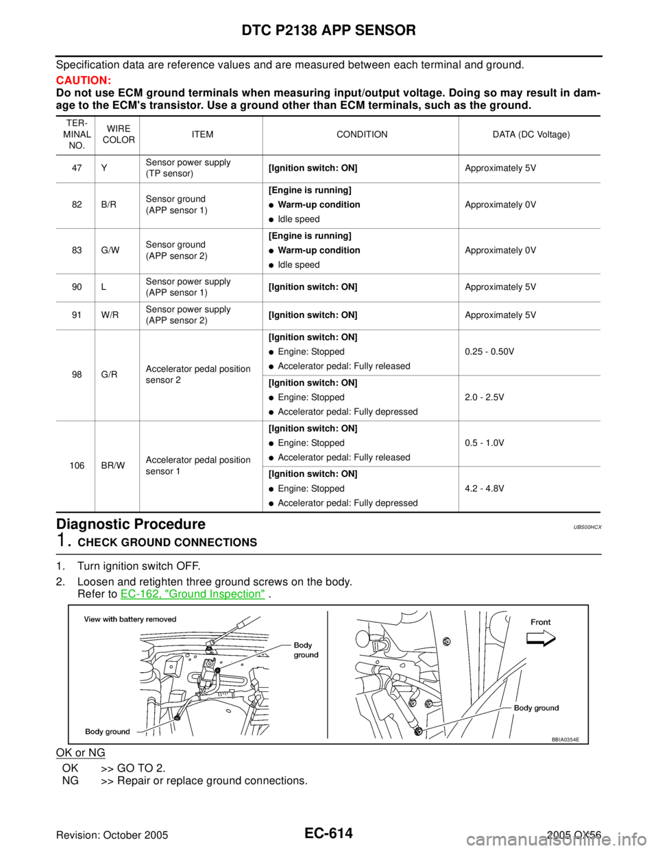
1. CHECK GROUND CONNECTIONS
1. Turn ignition switch OFF.
2. Loosen and retighten three ground screws on the body.
Refer to EC-162, "
Ground Inspection" .
OK or NG
OK >> GO TO 2.
NG >> Repair or replace ground connections.
TER-
MINAL
NO.WIRE
COLORITEM CONDITION DATA (DC Voltage)
47 YSensor power supply
(TP sensor)[Ignition switch: ON]Approximately 5V
82 B/RSensor ground
(APP sensor 1)[Engine is running]
�Warm-up condition
�Idle speedApproximately 0V
83 G/WSensor ground
(APP sensor 2)[Engine is running]
�Warm-up condition
�Idle speedApproximately 0V
90 LSensor power supply
(APP sensor 1)[Ignition switch: ON]Approximately 5V
91 W/RSensor power supply
(APP sensor 2)[Ignition switch: ON]Approximately 5V
98 G/RAccelerator pedal position
sensor 2[Ignition switch: ON]
�Engine: Stopped
�Accelerator pedal: Fully released0.25 - 0.50V
[Ignition switch: ON]
�Engine: Stopped
�Accelerator pedal: Fully depressed2.0 - 2.5V
106 BR/WAccelerator pedal position
sensor 1[Ignition switch: ON]
�Engine: Stopped
�Accelerator pedal: Fully released0.5 - 1.0V
[Ignition switch: ON]
�Engine: Stopped
�Accelerator pedal: Fully depressed4.2 - 4.8V
BBIA0354E
Page 1812 of 3419
IGNITION SIGNAL
EC-621
C
D
E
F
G
H
I
J
K
L
MA
EC
Revision: October 20052005 QX56
Specification data are reference values and are measured between each terminal and ground.
CAUTION:
Do not use ECM ground terminals when measuring input/output voltage. Doing so may result in dam-
age to the ECM's transistor. Use a ground other than ECM terminals, such as the ground.
TER-
MINAL
NO.WIRE
COLORITEM CONDITION DATA (DC Voltage)
111 W / BECM relay
(Self shut-off)[Engine is running]
[Ignition switch: OFF]
�For a few seconds after turning ignition
switch OFF0 - 1.5V
[Ignition switch: OFF]
�More than a few seconds after turning igni-
tion switch OFFBATTERY VOLTAGE
(11 - 14V)
11 9
120BR
BRPower supply for ECM[Ignition switch: ON]BATTERY VOLTAGE
(11 - 14V)
Page 1814 of 3419
IGNITION SIGNAL
EC-623
C
D
E
F
G
H
I
J
K
L
MA
EC
Revision: October 20052005 QX56
Specification data are reference values and are measured between each terminal and ground.
Pulse signal is measured by CONSULT-II.
CAUTION:
Do not use ECM ground terminals when measuring input/output voltage. Doing so may result in dam-
age to the ECM's transistor. Use a ground other than ECM terminals, such as the ground.
: Average voltage for pulse signal (Actual pulse signal can be confirmed by oscilloscope.)TER-
MINAL
NO.WIRE
COLORITEM CONDITION DATA (DC Voltage)
46
60
61
62L/R
GR/R
O/W
Y/RIgnition signal No. 7
Ignition signal No. 5
Ignition signal No. 3
Ignition signal No. 1[Engine is running]
�Warm-up condition
�Idle speed
NOTE:
The pulse cycle changes depending on rpm at
idle.0 - 0.2V
[Engine is running]
�Warm-up condition
�Engine speed: 2,000 rpm.0.1 - 0.4V
PBIB0044E
PBIB0045E
Page 1816 of 3419

IGNITION SIGNAL
EC-625
C
D
E
F
G
H
I
J
K
L
MA
EC
Revision: October 20052005 QX56
Specification data are reference values and are measured between each terminal and ground.
Pulse signal is measured by CONSULT-II.
CAUTION:
Do not use ECM ground terminals when measuring input/output voltage. Doing so may result in dam-
age to the ECM's transistor. Use a ground other than ECM terminals, such as the ground.
: Average voltage for pulse signal (Actual pulse signal can be confirmed by oscilloscope.)
Diagnostic ProcedureUBS00L1C
1. CHECK ENGINE START
Turn ignition switch OFF, and restart engine.
Is engine running?
Ye s o r N o
Yes (With CONSULT-II)>>GO TO 2.
Yes (Without CONSULT-II)>>GO TO 3.
No >> GO TO 4.
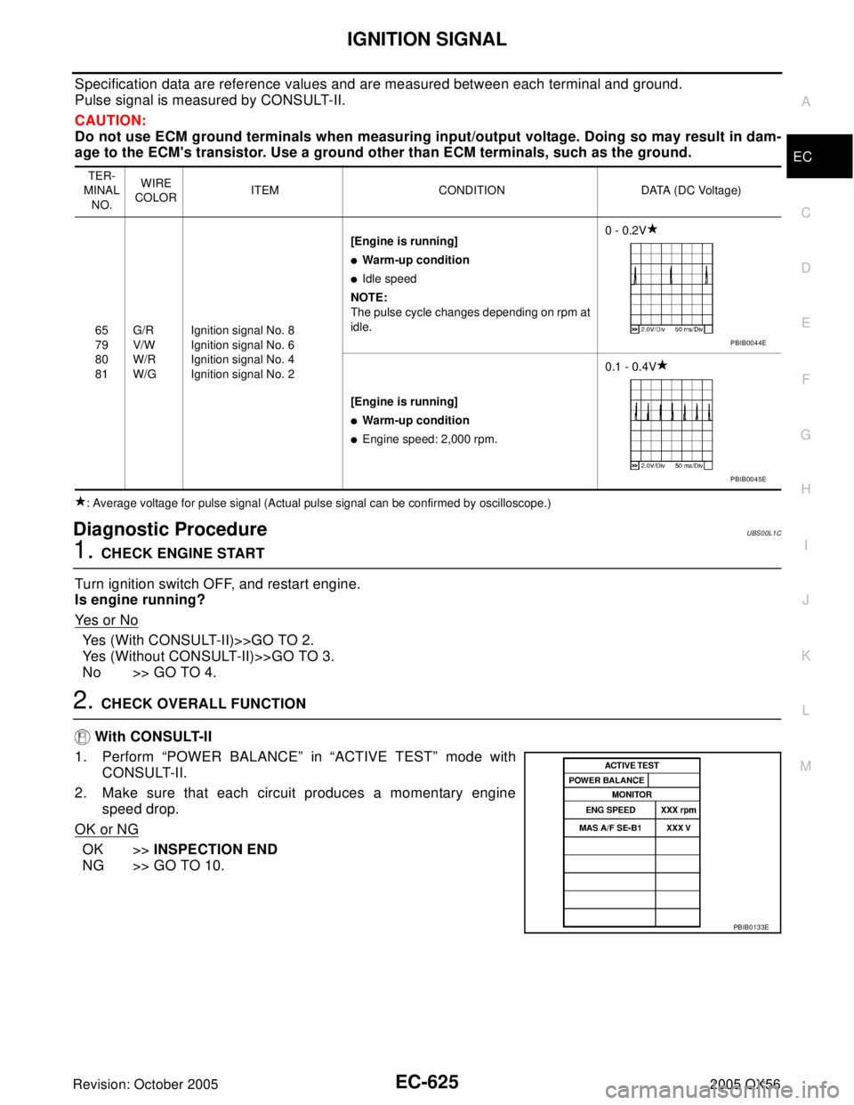
2. CHECK OVERALL FUNCTION
With CONSULT-II
1. Perform “POWER BALANCE” in “ACTIVE TEST” mode with
CONSULT-II.
2. Make sure that each circuit produces a momentary engine
speed drop.
OK or NG
OK >>INSPECTION END
NG >> GO TO 10.
TER-
MINAL
NO.WIRE
COLORITEM CONDITION DATA (DC Voltage)
65
79
80
81G/R
V/W
W/R
W/GIgnition signal No. 8
Ignition signal No. 6
Ignition signal No. 4
Ignition signal No. 2[Engine is running]
�Warm-up condition
�Idle speed
NOTE:
The pulse cycle changes depending on rpm at
idle.0 - 0.2V
[Engine is running]
�Warm-up condition
�Engine speed: 2,000 rpm.0.1 - 0.4V
PBIB0044E
PBIB0045E
PBIB0133E
Page 1817 of 3419
EC-626Revision: October 2005
IGNITION SIGNAL
2005 QX56
3. CHECK OVERALL FUNCTION
Without CONSULT-II
1. Let engine idle.
2. Read the voltage signal between ECM terminals 46, 60, 61, 62,
65, 79, 80, 81 and ground with an oscilloscope.
3. Verify that the oscilloscope screen shows the signal wave as
shown below.
NOTE:
The pulse cycle changes depending on rpm at idle.
OK or NG
OK >>INSPECTION END
NG >> GO TO 10.
4. CHECK IGNITION COIL POWER SUPPLY CIRCUIT-I
1. Turn ignition switch OFF, wait at least 10 seconds and then turn ON.
2. Check voltage between ECM terminals 119, 120 and ground
with CONSULT-II or tester.
OK or NG
OK >> GO TO 5.
NG >> Go to EC-157, "
POWER SUPPLY AND GROUND CIR-
CUIT" .
PBIB2094E
PBIB0044E
Voltage: Battery voltage
MBIB0034E
Page 1821 of 3419

EC-630Revision: October 2005
IGNITION SIGNAL
2005 QX56
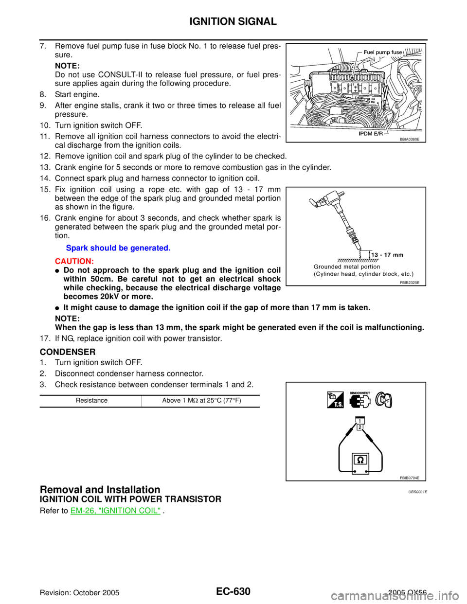
7. Remove fuel pump fuse in fuse block No. 1 to release fuel pres-
sure.
NOTE:
Do not use CONSULT-II to release fuel pressure, or fuel pres-
sure applies again during the following procedure.
8. Start engine.
9. After engine stalls, crank it two or three times to release all fuel
pressure.
10. Turn ignition switch OFF.
11. Remove all ignition coil harness connectors to avoid the electri-
cal discharge from the ignition coils.
12. Remove ignition coil and spark plug of the cylinder to be checked.
13. Crank engine for 5 seconds or more to remove combustion gas in the cylinder.
14. Connect spark plug and harness connector to ignition coil.
15. Fix ignition coil using a rope etc. with gap of 13 - 17 mm
between the edge of the spark plug and grounded metal portion
as shown in the figure.
16. Crank engine for about 3 seconds, and check whether spark is
generated between the spark plug and the grounded metal por-
tion.
CAUTION:
�Do not approach to the spark plug and the ignition coil
within 50cm. Be careful not to get an electrical shock
while checking, because the electrical discharge voltage
becomes 20kV or more.
�It might cause to damage the ignition coil if the gap of more than 17 mm is taken.
NOTE:
When the gap is less than 13 mm, the spark might be generated even if the coil is malfunctioning.
17. If NG, replace ignition coil with power transistor.
CONDENSER
1. Turn ignition switch OFF.
2. Disconnect condenser harness connector.
3. Check resistance between condenser terminals 1 and 2.
Removal and InstallationUBS00L1E
IGNITION COIL WITH POWER TRANSISTOR
Refer to EM-26, "IGNITION COIL" . Spark should be generated.
BBIA0380E
PBIB2325E
Resistance Above 1 MΩ at 25°C (77°F)
PBIB0794E