Page 2774 of 3419

STEERING WHEEL
PS-7
C
D
E
F
H
I
J
K
L
MA
B
PS
Revision: October 20052005 QX56
STEERING WHEELPFP:48430
On-Vehicle Inspection and ServiceEGS000UC
CHECKING CONDITION OF INSTALLATION
�Check installation condition of steering gear assembly, front suspension, axle and steering column.
�Check if movement exists when steering wheel is moved up and down, to the left and right and to the axial
direction.
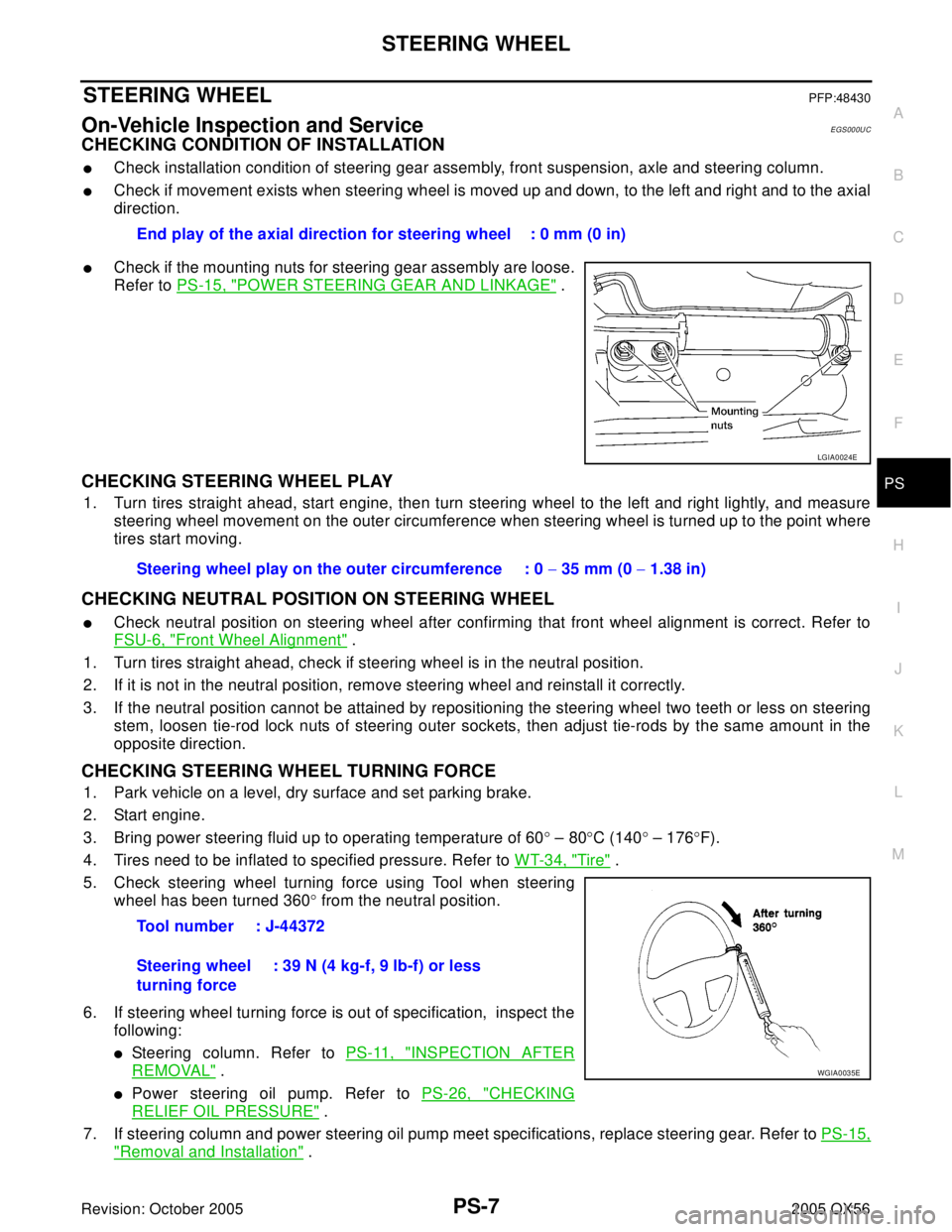
�Check if the mounting nuts for steering gear assembly are loose.
Refer to PS-15, "
POWER STEERING GEAR AND LINKAGE" .
CHECKING STEERING WHEEL PLAY
1. Turn tires straight ahead, start engine, then turn steering wheel to the left and right lightly, and measure
steering wheel movement on the outer circumference when steering wheel is turned up to the point where
tires start moving.
CHECKING NEUTRAL POSITION ON STEERING WHEEL
�Check neutral position on steering wheel after confirming that front wheel alignment is correct. Refer to
FSU-6, "
Front Wheel Alignment" .
1. Turn tires straight ahead, check if steering wheel is in the neutral position.
2. If it is not in the neutral position, remove steering wheel and reinstall it correctly.
3. If the neutral position cannot be attained by repositioning the steering wheel two teeth or less on steering
stem, loosen tie-rod lock nuts of steering outer sockets, then adjust tie-rods by the same amount in the
opposite direction.
CHECKING STEERING WHEEL TURNING FORCE
1. Park vehicle on a level, dry surface and set parking brake.
2. Start engine.
3. Bring power steering fluid up to operating temperature of 60° – 80°C (140° – 176°F).
4. Tires need to be inflated to specified pressure. Refer to WT-34, "
Tire" .
5. Check steering wheel turning force using Tool when steering
wheel has been turned 360° from the neutral position.
6. If steering wheel turning force is out of specification, inspect the
following:
�Steering column. Refer to PS-11, "INSPECTION AFTER
REMOVAL" .
�Power steering oil pump. Refer to PS-26, "CHECKING
RELIEF OIL PRESSURE" .
7. If steering column and power steering oil pump meet specifications, replace steering gear. Refer to PS-15,
"Removal and Installation" . End play of the axial direction for steering wheel : 0 mm (0 in)
LGIA0024E
Steering wheel play on the outer circumference : 0 − 35 mm (0 − 1.38 in)
Tool number : J-44372
Steering wheel
turning force: 39 N (4 kg-f, 9 lb-f) or less
WGIA0035E
Page 2793 of 3419

PS-26
POWER STEERING OIL PUMP
Revision: October 20052005 QX56
POWER STEERING OIL PUMPPFP:49110
On-Vehicle Inspection and ServiceEGS000UJ
CHECKING RELIEF OIL PRESSURE
CAUTION:
Before starting work, confirm belt tension is proper.
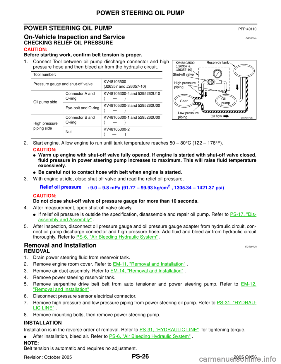
1. Connect Tool between oil pump discharge connector and high
pressure hose and then bleed air from the hydraulic circuit.
2. Start engine. Allow engine to run until tank temperature reaches 50 – 80°C (122 – 176°F).
CAUTION:
�Warm up engine with shut-off valve fully opened. If engine is started with shut-off valve closed,
fluid pressure in power steering pump increases to maximum. This will raise fluid temperature
excessively.
�Be careful not to contact hose with belt when engine is started.
3. With engine at idle, close shut-off valve and read the relief oil pressure.
CAUTION:
Do not close shut-off valve of pressure gauge for more than 10 seconds.
4. After measurement, open shut-off valve slowly.
�If relief oil pressure is outside the specification, disassemble and repair oil pump. Refer to PS-17, "Dis-
assembly and Assembly" .
5. After inspection, disconnect oil pressure gauge and oil pressure gauge adapter from hydraulic circuit, con-
nect oil pump discharge connector and high pressure hose. Add fluid and bleed air from hydraulic circuit
thoroughly. Refer to PS-6, "
Air Bleeding Hydraulic System" .
Removal and InstallationEGS000UK
REMOVAL
1. Drain power steering fluid from reservoir tank.
2. Remove engine room cover. Refer to EM-11, "
Removal and Installation" .
3. Remove air duct assembly. Refer to EM-14, "
Removal and Installation" .
4. Remove power steering reservoir tank.
5. Remove serpentine drive belt belt from auto tensioner and power steering pump. Refer to EM-12,
"Removal and Installation" .
6. Disconnect pressure sensor electrical connector.
7. Remove high pressure and low pressure piping from power steering oil pump. Refer to PS-31, "
HYDRAU-
LIC LINE" .
8. Remove mounting bolts, then remove power steering pump.
INSTALLATION
Installation is in the reverse order of removal. Refer to PS-31, "HYDRAULIC LINE" for tightening torque.
�After installation, bleed air. Refer to PS-6, "Air Bleeding Hydraulic System" .
NOTE:
Belt tension is automatic and requires no adjustment.
Tool number:
Pressure gauge and shut-off valveKV48103500
(J26357 and J26357-10)
Oil pump sideConnector A and
O-ringKV48105300-4 and 5295262U10
(—)
Eye-bolt and O-ringKV48105300-3 and 5295262U00
(—)
High pressure
piping sideConnector B and
O-ringKV48105300-1 and 5295262U00
(—)
NutKV48105300-2
( — )
Relief oil pressure
: 9.0 – 9.8 mPa (91.77 – 99.93 kg/cm2 , 1305.34 – 1421.37 psi)
SGIA0570E
Page 2854 of 3419

FRONT OIL SEAL
RFD-7
C
E
F
G
H
I
J
K
L
MA
B
RFD
Revision: October 20052005 QX56
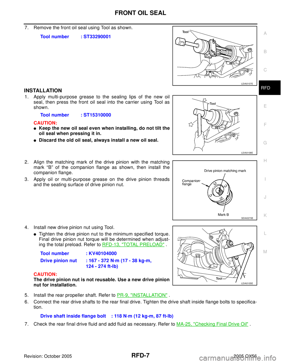
7. Remove the front oil seal using Tool as shown.
INSTALLATION
1. Apply multi-purpose grease to the sealing lips of the new oil
seal, then press the front oil seal into the carrier using Tool as
shown.
CAUTION:
�Keep the new oil seal even when installing, do not tilt the
oil seal when pressing it in.
�Discard the old oil seal, always install a new oil seal.
2. Align the matching mark of the drive pinion with the matching
mark “B” of the companion flange as shown, then install the
companion flange.
3. Apply oil or multi-purpose grease on the drive pinion threads
and the seating surface of drive pinion nut.
4. Install new drive pinion nut using Tool.
�Tighten the drive pinion nut to the minimum specified torque.
Final drive pinion nut torque will be determined when adjust-
ing the total preload. Refer to RFD-13, "
TOTAL PRELOAD" .
CAUTION:
The drive pinion nut is not reusable. Use a new drive pinion
nut for installation.
5. Install the rear propeller shaft. Refer to PR-9, "
INSTALLATION" .
6. Connect the rear drive shafts to the rear final drive. Tighten the drive shaft inside flange bolts to specifica-
tion.
7. Check the rear final drive fluid and add fluid as necessary. Refer to MA-25, "
Checking Final Drive Oil" . Tool number : ST33290001
LDIA0107E
Tool number : ST15310000
LDIA0108E
SDIA0270E
Tool number : KV40104000
Drive pinion nut : 167 - 372 N·m (17 - 38 kg-m,
124 - 274 ft-lb)
LDIA0105E
Drive shaft inside flange bolt : 118 N·m (12 kg-m, 87 ft-lb)
Page 2858 of 3419
REAR FINAL DRIVE ASSEMBLY
RFD-11
C
E
F
G
H
I
J
K
L
MA
B
RFD
Revision: October 20052005 QX56
INSTALLATION
Installation is in the reverse order of removal.
CAUTION:
After installation, check the final drive oil level. Refer to MA-25, "
Checking Final Drive Oil" .
Page 2871 of 3419

RFD-24
REAR FINAL DRIVE ASSEMBLY
Revision: October 20052005 QX56
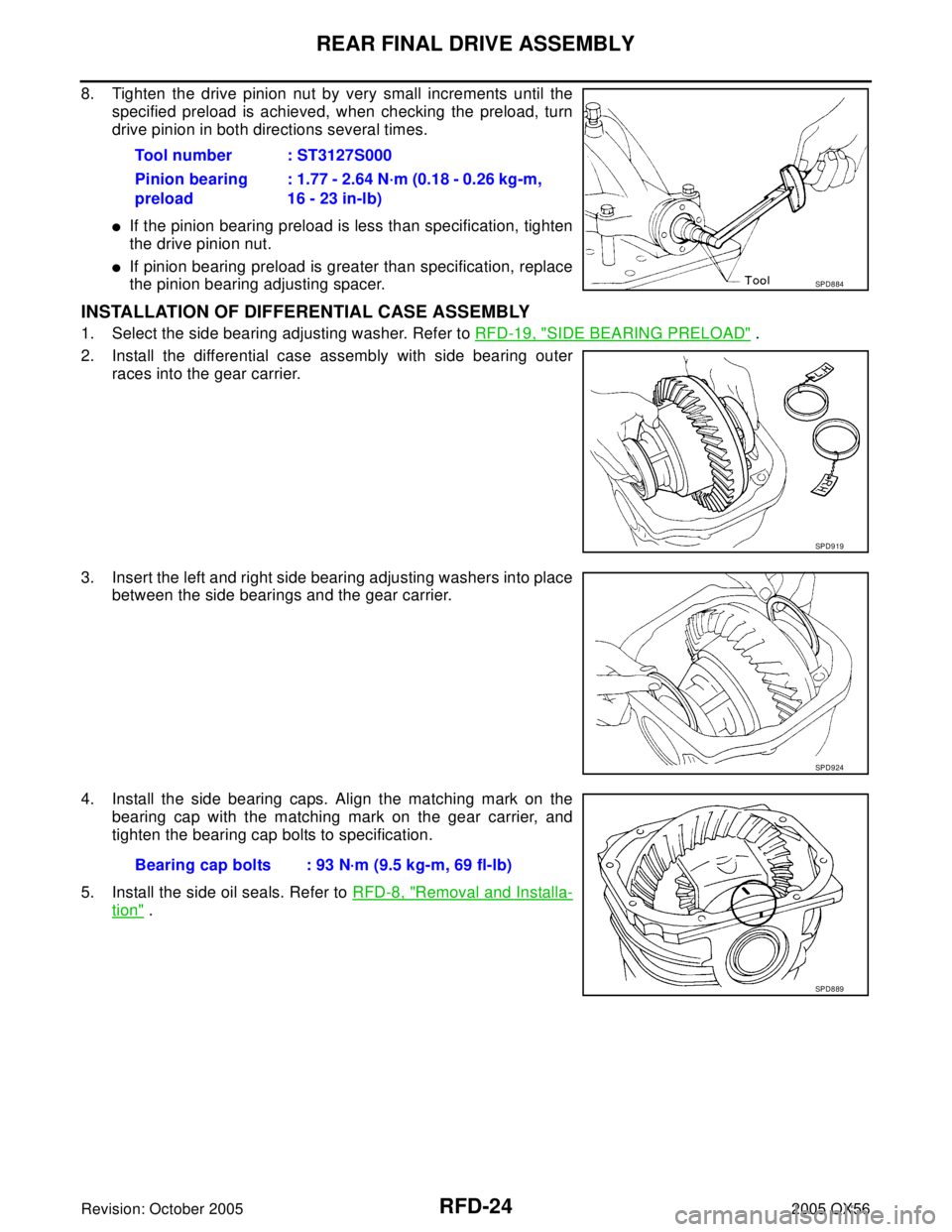
8. Tighten the drive pinion nut by very small increments until the
specified preload is achieved, when checking the preload, turn
drive pinion in both directions several times.
�If the pinion bearing preload is less than specification, tighten
the drive pinion nut.
�If pinion bearing preload is greater than specification, replace
the pinion bearing adjusting spacer.
INSTALLATION OF DIFFERENTIAL CASE ASSEMBLY
1. Select the side bearing adjusting washer. Refer to RFD-19, "SIDE BEARING PRELOAD" .
2. Install the differential case assembly with side bearing outer
races into the gear carrier.
3. Insert the left and right side bearing adjusting washers into place
between the side bearings and the gear carrier.
4. Install the side bearing caps. Align the matching mark on the
bearing cap with the matching mark on the gear carrier, and
tighten the bearing cap bolts to specification.
5. Install the side oil seals. Refer to RFD-8, "
Removal and Installa-
tion" . Tool number : ST3127S000
Pinion bearing
preload: 1.77 - 2.64 N·m (0.18 - 0.26 kg-m,
16 - 23 in-lb)
SPD8 84
SPD9 19
SPD9 24
Bearing cap bolts : 93 N·m (9.5 kg-m, 69 fl-lb)
SPD8 89