Page 156 of 3419

TROUBLE DIAGNOSIS
AT-85
D
E
F
G
H
I
J
K
L
MA
B
AT
Revision: October 20052005 QX56
CONSULT-II SETTING PROCEDURE
CAUTION:
If CONSULT-II is used with no connection of CONSULT-II CONVERTER, malfunctions might be
detected in self-diagnosis depending on control unit which carry out CAN communication.
�For details, refer to the separate “CONSULT-II Operations Man-
ual”.
1. Turn ignition switch “OFF”.
2. Connect CONSULT-II and CONSULT-II CONVERTER to data
link connector, which is located in instrument lower panel on
driver side.
3. Turn ignition switch “ON”. (Do not start engine.)
4. Touch “START (NISSAN BASED VHCL)”.
5. Touch “A/T”.
If “A/T” is not indicated, go to GI-39, "
CONSULT-II Data Link
Connector (DLC) Circuit" .
6. Perform each diagnostic test mode according to each service
procedure.
SELF-DIAGNOSTIC RESULT MODE
Operation Procedure
After performing AT-85, "SELF-DIAGNOSTIC RESULT MODE" , place check marks for results on the AT-45,
"DIAGNOSTIC WORKSHEET" . Reference pages are provided following the items.
1. Perform “CONSULT-II SETTING PROCEDURE” Refer to AT - 8 5 , "
CONSULT-II SETTING PROCEDURE" .
2. Touch “SELF-DIAG RESULTS”.
Display shows malfunction experienced since the last erasing
operation.
BBIA0369E
BCIA0029E
BCIA0030E
BCIA0031E
Page 157 of 3419
Malfunction is detected when...TCM self-
diagnosisOBD-II")
AT-86
TROUBLE DIAGNOSIS
Revision: October 20052005 QX56
Display Items List
X: Applicable, —: Not applicable
Items (CONSULT-II
screen terms)Malfunction is detected when...TCM self-
diagnosisOBD-II (DTC)
“A/T” with
CONSULT-IIMIL indicator
lamp*1,
“ENGINE” with
CONSULT-II or
GST
CAN COMM CIRCUIT
�When a malfunction is detected in CAN communications U1000 U1000
STARTER RELAY/
CIRC
�If this signal is ON other than in P or N position, this is judged to be a
malfunction.
(And if it is OFF in P or N position, this too is judged to be a malfunc-
tion.)P0615 —
TCM
�TCM is malfunctioning. P0700 P0700
PNP SW/CIRC
�PNP switch 1-4 signals input with impossible pattern
�“P” position is detected from N position without any other position
being detected in between.P0705 P0705
VEH SPD SEN/CIR AT
(Revolution sensor)
�Signal from vehicle speed sensor A/T (Revolution sensor) not input
due to cut line or the like
�Unexpected signal input during running
�After ignition switch is turned ON, unexpected signal input from vehicle
speed sensor MTR before the vehicle starts movingP0720 P0720
ENGINE SPEED SIG
�TCM does not receive the CAN communication signal from the ECM. P0725 —
TCC SOLENOID/CIRC
�Normal voltage not applied to solenoid due to cut line, short, or the like P0740 P0740
A/T TCC S/V FNCTN
�A/T cannot perform lock-up even if electrical circuit is good.
�TCM detects as irregular by comparing difference value with slip rota-
tion.P0744 P0744*2
L/PRESS SOL/CIRC
�Normal voltage not applied to solenoid due to cut line, short, or the like
�TCM detects as irregular by comparing target value with monitor value.P0745 P0745
TCM·RAM
�TCM memory (RAM) is malfunctioning. P1702 —
TCM·ROM
�TCM memory (ROM) is malfunctioning. P1703 —
TP SEN/CIRC A/T
�TCM does not receive the proper accelerator pedal position signals
(input by CAN communication) from ECM.P1705 P1705
ATF TEMP SEN/CIRC
� During running, the ATF temperature sensor signal voltage is exces-
sively high or lowP1710 P0710
TURBINE REV S/CIRC
�TCM does not receive the proper voltage signal from the sensor.
�TCM detects an irregularity only at position of 4th gear for turbine revo-
lution sensor 2.P1716 P1716
VEH SPD SE/CIR·MTR
�Signal (CAN communication) from vehicle speed sensor MTR not input
due to cut line or the like
�Unexpected signal input during runningP1721 —
A/T INTERLOCK
�Except during shift change, the gear position and ATF pressure switch
states are monitored and comparative judgement made.P1730 P1730
A/T 1ST E/BRAKING
�Each ATF pressure switch and solenoid current is monitored and if a
pattern is detected having engine braking 1st gear other than in the "1"
position, a malfunction is detected.P1731 —
I/C SOLENOID/CIRC
�Normal voltage not applied to solenoid due to functional malfunction,
cut line, short, or the like
�TCM detects as irregular by comparing target value with monitor value.P1752 P1752
Page 159 of 3419
AT-88
TROUBLE DIAGNOSIS
Revision: October 20052005 QX56
*1: Refer to EC-64, "Malfunction Indicator Lamp (MIL)" .
*2:These malfunctions cannot be displayed MIL if another malfunction is assigned to MIL.
How to Erase Self-diagnostic Results
1. Perform “CONSULT-II SETTING PROCEDURE” Refer to AT-85, "CONSULT-II SETTING PROCEDURE" .
2. Touch “SELF-DIAG RESULTS”.
3. Touch ”ERASE”. (The self-diagnostic results will be erased.)
ATF PRES SW 6/CIRC
�TCM detects that actual gear ratio is normal, and relation between
gear position and condition of ATF pressure switch 6 is irregular during
depressing accelerator pedal. (Other than during shift change)P1846 —
NO DTC IS
DETECTED FUR-
THER TESTING MAY
BE REQUIRED
�No NG item has been detected. X X Items (CONSULT-II
screen terms)Malfunction is detected when...TCM self-
diagnosisOBD-II (DTC)
“A/T” with
CONSULT-IIMIL indicator
lamp*1,
“ENGINE” with
CONSULT-II or
GST
BCIA0031E
PCIA0061E
Page 160 of 3419

TROUBLE DIAGNOSIS
AT-89
D
E
F
G
H
I
J
K
L
MA
B
AT
Revision: October 20052005 QX56
DATA MONITOR MODE
Operation Procedure
1. Perform “CONSULT-II SETTING PROCEDURE”. Refer to AT-85, "CONSULT-II SETTING PROCEDURE"
.
2. Touch “DATA MONITOR”.
NOTE:
When malfunction is detected, CONSULT-II performs
“REAL-TIME DIAGNOSIS”. Also, any malfunction detected
while in this mode will be displayed at real time.
Display Items List
X: Standard, —: Not applicable
BCIA0031E
Monitored item (Unit)Monitor Item Selection
Remarks ECU
INPUT
SIGNALSMAIN SIG-
NALSSELEC-
TION
FROM
MENU
VHCL/S SE·A/T (km/h) X X X Revolution sensor
VHCL/S SE·MTR (km/h) X — X
ACCELE POSI (0.0/8) X — X Accelerator pedal position signal
THROTTLE POSI (0.0/8) X X XDegree of opening for accelerator recognized by
the TCM
For fail-safe operation, the specific value used
for control is displayed.
CLSD THL POS (ON-OFF display) X — X
Signal input with CAN communications
W/O THL POS (ON-OFF display) X — X
BRAKE SW (ON-OFF display) X — X Stop lamp switch
GEAR — X XGear position recognized by the TCM updated
after gear-shifting
ENGINE SPEED (rpm) X X X
TURBINE REV (rpm) X X X
OUTPUT REV (rpm) X X X
GEAR RATIO — X X
TC SLIP SPEED (rpm) — X XDifference between engine speed and torque
converter input shaft speed
F SUN GR REV (rpm) — — X
F CARR GR REV (rpm) — — X
AT F T E M P S E 1 ( V ) X — X
AT F T E M P S E 2 ( V ) X — X
AT F T E M P 1 (°C) — X X
AT F T E M P 2 (°C) — X X
BATTERY VOLT (V) X — X
ATF PRES SW 1 (ON-OFF display) X X X (for FR/B solenoid)
ATF PRES SW 2 (ON-OFF display) X X X (for LC/B solenoid)
ATF PRES SW 3 (ON-OFF display) X X X (for I/C solenoid)
ATF PRES SW 5 (ON-OFF display) X X X (for D/C solenoid)
Page 161 of 3419
 X X X (for HLR/C solenoid)
PNP SW 1 (ON-OFF display) X — X
PNP SW 2 (ON-OFF display) X — X
PNP SW 3 (ON-OFF d")
AT-90
TROUBLE DIAGNOSIS
Revision: October 20052005 QX56
ATF PRES SW 6 (ON-OFF display) X X X (for HLR/C solenoid)
PNP SW 1 (ON-OFF display) X — X
PNP SW 2 (ON-OFF display) X — X
PNP SW 3 (ON-OFF display) X — X
PNP SW 4 (ON-OFF display) X — X
SLCT LVR POSI — X XSelector lever position is recognized by the
TCM.
For fail-safe operation, the specific value used
for control is displayed.
1 POSITION SW (ON-OFF display) X — X 1st position switch
OD CONT SW (ON-OFF display) X — X 4th position switch
POWERSHIFT SW (ON-OFF display) X — X
Not mounted but displayed. HOLD SW (ON-OFF display) X — X
MANU MODE SW (ON-OFF display) X — X
NON M-MODE SW (ON-OFF display) X — X
UP SW LEVER (ON-OFF display) X — X
DOWN SW LEVER (ON-OFF display) X — X
SFT UP ST SW (ON-OFF display) — — X
SFT DWN ST SW (ON-OFF display) — — X
ASCD-OD CUT (ON-OFF display) — — X
ASCD-CRUISE (ON-OFF display) — — X
ABS SIGNAL (ON-OFF display) — — X
ACC OD CUT (ON-OFF display) — — X
ICC (Intelligent cruise control)
ACC SIGNAL (ON-OFF display) — — X
TCS GR/P KEEP (ON-OFF display) — — X
TCS SIGNAL 2 (ON-OFF display) — — X
TCS SIGNAL 1 (ON-OFF display) — — X
TCC SOLENOID (A) — X X
LINE PRES SOL (A) — X X
I/C SOLENOID (A) — X X
FR/B SOLENOID (A) — X X
D/C SOLENOID (A) — X X
HLR/C SOL (A) — X X
ON OFF SOL (ON-OFF display) — — X LC/B solenoid
TCC SOL MON (A) — — X
L/P SOL MON (A) — — X
I/C SOL MON (A) — — X
FR/B SOL MON (A) — — X
D/C SOL MON (A) — — X
HLR/C SOL MON (A) — — X
ONOFF SOL MON (ON-OFF display) — — X LC/B solenoid
P POSI IND (ON-OFF display) — — XMonitored item (Unit)Monitor Item Selection
Remarks ECU
INPUT
SIGNALSMAIN SIG-
NALSSELEC-
TION
FROM
MENU
Page 162 of 3419
 — — X
N POSI IND (ON-OFF display) — — X
D POSI IND (ON-OFF display) — — X
4TH")
TROUBLE DIAGNOSIS
AT-91
D
E
F
G
H
I
J
K
L
MA
B
AT
Revision: October 20052005 QX56
R POSI IND (ON-OFF display) — — X
N POSI IND (ON-OFF display) — — X
D POSI IND (ON-OFF display) — — X
4TH POSI IND (ON-OFF display) — — X
3RD POSI IND (ON-OFF display) — — X
2ND POSI IND (ON-OFF display) — — X
1ST POSI IND (ON-OFF display) — — X
MANU MODE IND (ON-OFF display) — — X
Not mounted but displayed.
POWER M LAMP (ON-OFF display) — — X
F-SAFE IND/L (ON-OFF display) — — X
ATF WARN LAMP (ON-OFF display) — — X
BACK-UP LAMP (ON-OFF display) — — X
STARTER RELAY (ON-OFF display) — — X
PNP SW3 MON (ON-OFF display) — — X
C/V CLB ID1 — — X
C/V CLB ID2 — — X
C/V CLB ID3 — — X
UNIT CLB ID1 — — X
UNIT CLB ID2 — — X
UNIT CLB ID3 — — X
TRGT GR RATIO — — X
TRGT PRES TCC (kPa) — — X
TRGT PRES L/P (kPa) — — X
TRGT PRES I/C (kPa) — — X
TRGT PRE FR/B (kPa) — — X
TRGT PRES D/C (kPa) — — X
TRG PRE HLR/C (kPa) — — X
SHIFT PATTERN — — X
DRV CST JUDGE — — X
START RLY MON — — X
NEXT GR POSI — — X
SHIFT MODE — — X
MANU GR POSI — — X
VEHICLE SPEED (km/h) — X X Vehicle speed recognized by the TCM.
Voltage (V) — — XDisplays the value measured by the voltage
probe.
Frequency (Hz) — — X
The value measured by the pulse probe is dis-
played. DUTY-HI (high) (%) — — X
DUTY-LOW (low) (%) — — X
PLS WIDTH-HI (ms) — — X
PLS WIDTH-LOW (ms) — — XMonitored item (Unit)Monitor Item Selection
Remarks ECU
INPUT
SIGNALSMAIN SIG-
NALSSELEC-
TION
FROM
MENU
Page 164 of 3419
TROUBLE DIAGNOSIS
AT-93
D
E
F
G
H
I
J
K
L
MA
B
AT
Revision: October 20052005 QX56
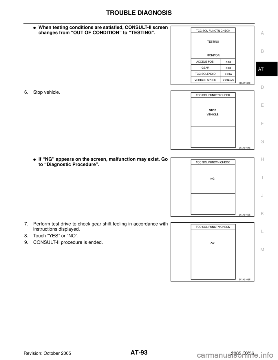
�When testing conditions are satisfied, CONSULT-II screen
changes from “OUT OF CONDITION” to “TESTING”.
6. Stop vehicle.
�If “NG” appears on the screen, malfunction may exist. Go
to “Diagnostic Procedure”.
7. Perform test drive to check gear shift feeling in accordance with
instructions displayed.
8. Touch “YES” or “NO”.
9. CONSULT-II procedure is ended.
SCIA5161E
SCIA5164E
SCIA5162E
SCIA5163E
Page 165 of 3419
AT-94
TROUBLE DIAGNOSIS
Revision: October 20052005 QX56
�If “NG” appears on the screen, a malfunction may exist.
Go to “Diagnostic Procedure”.
Display Items List
*: Do not use, but displayed.
SCIA5162E
DTC work support item Description Check item
I/C SOL FUNCTN CHECK* — —
FR/B SOL FUNCTN CHECK* — —
D/C SOL FUNCTN CHECK* — —
HLR/C SOL FUNCTN CHECK* — —
LC/B SOL FUNCTN CHECK* — —
TCC SOL FUNCTN CHECKFollowing items for “TCC solenoid function (lock-up) ” can be con-
firmed.
�Self-diagnosis status (whether the diagnosis is being conducted
or not)
�Self-diagnosis result (OK or NG)
�TCC solenoid valve
�Hydraulic control circuit
\" .
*2:These malfunctions cannot be displayed MIL if another malfunction is assigned to MIL")