Page 2911 of 3419
RSU-36
SUSPENSION ARM
Revision: October 20052005 QX56
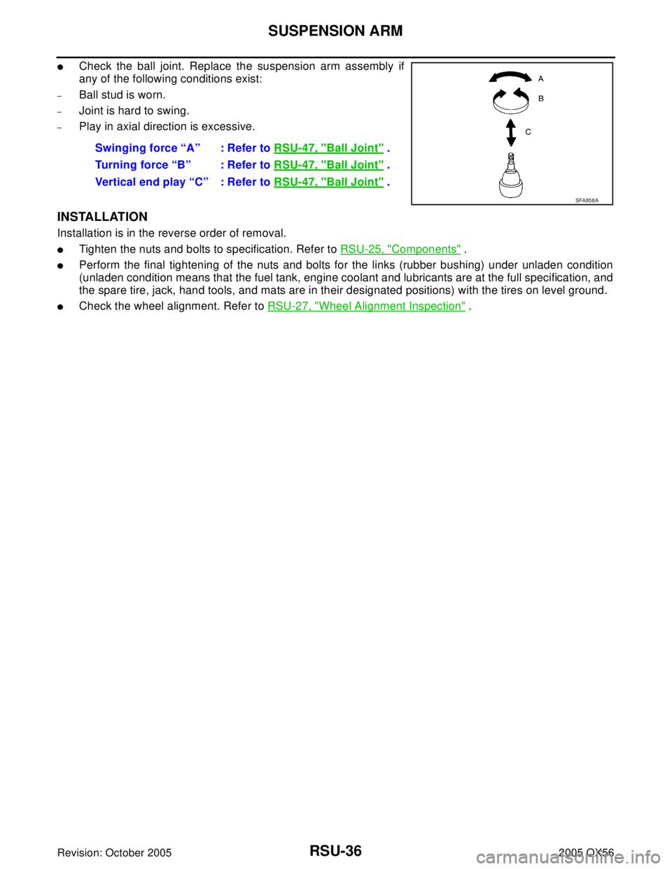
�Check the ball joint. Replace the suspension arm assembly if
any of the following conditions exist:
–Ball stud is worn.
–Joint is hard to swing.
–Play in axial direction is excessive.
INSTALLATION
Installation is in the reverse order of removal.
�Tighten the nuts and bolts to specification. Refer to RSU-25, "Components" .
�Perform the final tightening of the nuts and bolts for the links (rubber bushing) under unladen condition
(unladen condition means that the fuel tank, engine coolant and lubricants are at the full specification, and
the spare tire, jack, hand tools, and mats are in their designated positions) with the tires on level ground.
�Check the wheel alignment. Refer to RSU-27, "Wheel Alignment Inspection" . Swinging force “A” : Refer to RSU-47, "
Ball Joint" .
Turning force “B” : Refer to RSU-47, "
Ball Joint" .
Vertical end play “C” : Refer to RSU-47, "
Ball Joint" .
SFA858A
Page 2913 of 3419
RSU-38
FRONT LOWER LINK
Revision: October 20052005 QX56
INSTALLATION
Installation is in the reverse order of removal.
�Tighten the nuts and bolts to specification. Refer to RSU-25, "Components" .
�Perform the final tightening of the nuts and bolts for the links (rubber bushing) under unladen condition
(unladen condition means that the fuel tank, engine coolant and lubricants are at the full specification, and
the spare tire, jack, hand tools, and mats are in their designated positions) with the tires on level ground.
�Check the wheel alignment. Refer to RSU-27, "Wheel Alignment Inspection" .
Page 2923 of 3419
RSU-48
SERVICE DATA AND SPECIFICATIONS (SDS)
Revision: October 20052005 QX56
Wheelarch Height (Unladen*1 )EES001HV
Unit: mm (in)
*1: Fuel, engine coolant and engine oil full. Spare tire, jack, hand tools and mats in designated positions.
*2: Verify the vehicle height. If vehicle height is not within ± 10 mm (0.39 in) of the specification, perform the control unit initialization pro-
cedure. Refer to RSU-46, "
Initialization Procedure" . Suspension type
Air leveling*
2
Applied model4x2 4x4
Front wheelarch height (Hf)913
(35.94)931
(36.65)
Rear wheelarch height (Hr)912
(35.91)932
(36.69)
LEIA0085E
Page 2938 of 3419

SC-1
STARTING & CHARGING SYSTEM
K ELECTRICAL
CONTENTS
C
D
E
F
G
H
I
J
L
M
SECTION SC
A
B
SC
Revision: October 20052005 QX56 PRECAUTIONS .......................................................... 2
Precautions for Supplemental Restraint System
(SRS) “AIR BAG” and “SEAT BELT PRE-TEN-
SIONER” .................................................................. 2
Wiring Diagrams and Trouble Diagnosis .................. 2
PREPARATION ........................................................... 3
Special Service Tool ................................................. 3
Commercial Service Tools ........................................ 3
BATTERY .................................................................... 4
How to Handle Battery ............................................. 4
METHODS OF PREVENTING OVER-DIS-
CHARGE ............................................................... 4
CHECKING ELECTROLYTE LEVEL .................... 4
SPECIFIC GRAVITY CHECK ............................... 5
CHARGING THE BATTERY ................................. 6
Trouble Diagnoses with Battery/Starting/Charging
System Tester .......................................................... 6
DIAGNOSTIC RESULT ITEM CHART .................. 8
Removal and Installation .......................................... 9
REMOVAL ............................................................. 9
INSTALLATION ..................................................... 9
STARTING SYSTEM ................................................ 10
System Description ................................................ 10
Wiring Diagram — START — ..................................11
Trouble Diagnoses with Battery/Starting/Charging
System Tester ........................................................ 12
DIAGNOSTIC RESULT ITEM CHART ................ 12
WORK FLOW ...................................................... 13DIAGNOSTIC PROCEDURE 1 ........................... 14
DIAGNOSTIC PROCEDURE 2 ........................... 15
MINIMUM SPECIFICATION OF CRANKING
VOLTAGE REFERENCING COOLANT TEM-
PERATURE ......................................................... 16
Removal and Installation ........................................ 16
REMOVAL ........................................................... 16
INSTALLATION ................................................... 16
CHARGING SYSTEM ............................................... 17
System Description ................................................. 17
Wiring Diagram — CHARGE — ............................. 18
Trouble Diagnoses with Battery/Starting/Charging
System Tester ......................................................... 19
DIAGNOSTIC RESULT ITEM CHART ................ 20
WORK FLOW ...................................................... 21
DIAGNOSTIC PROCEDURE 1 ........................... 22
DIAGNOSTIC PROCEDURE 2 ........................... 23
DIAGNOSTIC PROCEDURE 3 ........................... 23
DIAGNOSTIC PROCEDURE 4 ........................... 24
DIAGNOSTIC PROCEDURE 5 ........................... 26
MALFUNCTION INDICATOR .............................. 27
Removal and Installation ........................................ 27
REMOVAL ........................................................... 27
INSTALLATION ................................................... 27
SERVICE DATA AND SPECIFICATIONS (SDS) ...... 28
Battery .................................................................... 28
Starter ..................................................................... 28
Generator ............................................................... 28


Revision: October 20052005 QX56
Wheelarch Height (Unladen*1 )EES001HV
Unit: mm (in)
*1: Fuel, engine coolant and engine oil full. Spare tire, jack, hand to")