Page 2666 of 3419

PB-1
PARKING BRAKE SYSTEM
F BRAKES
CONTENTS
C
D
E
G
H
I
J
K
L
M
SECTION PB
A
B
PB
Revision: October 20052005 QX56 PREPARATION ........................................................... 2
Commercial Service Tools ........................................ 2
PARKING BRAKE SYSTEM ...................................... 3
On-Vehicle Service ................................................... 3
PEDAL STROKE ................................................... 3
INSPECTION ........................................................ 3
ADJUSTMENT ...................................................... 3
PARKING BRAKE CONTROL ................................... 4
Components ............................................................. 4
Removal and Installation .......................................... 4
REMOVAL ............................................................. 4
INSTALLATION ..................................................... 5PARKING BRAKE SHOE ........................................... 6
Removal and Installation .......................................... 6
COMPONENTS ..................................................... 6
REMOVAL ............................................................. 6
INSPECTION AFTER REMOVAL ......................... 7
INSTALLATION ..................................................... 7
SERVICE DATA AND SPECIFICATIONS (SDS) ........ 9
Parking Drum Brake ................................................. 9
Parking Brake Control .............................................. 9
Page 2667 of 3419
PB-2
PREPARATION
Revision: October 20052005 QX56
PREPARATIONPFP:00002
Commercial Service ToolsEFS004WW
Tool number
(Kent-Moore No.)
Tool nameDescription
—
(J-21177-A)
Brake drum clearence gaugeMeasuring rear rotor drum to parking
brake shoe clearance
Power toolLoosening bolts and nuts
WFIA0167E
PBIC0190E
Page 2668 of 3419

PARKING BRAKE SYSTEM
PB-3
C
D
E
G
H
I
J
K
L
MA
B
PB
Revision: October 20052005 QX56
PARKING BRAKE SYSTEMPFP:36010
On-Vehicle ServiceEFS004WX
PEDAL STROKE
�When parking brake pedal is operated with the specified force, make sure the stroke is within the specified
number of notches. Check by listening and counting the ratchet clicks.
INSPECTION
�Make sure the components are attached properly, checking for looseness or backlash.
�Check parking brake pedal assembly for bends, damage and cracks, and replace if necessary.
�Check cable for wear and damage, and replace if necessary.
�Check parking brake warning lamp switch for malfunction, and replace if necessary. Refer to DI-31, "Wir-
ing Diagram — WARN —" .
ADJUSTMENT
1. Remove lower driver instrument panel. Refer to IP-13, "Instrument Lower Cover LH" .
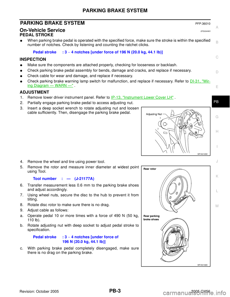
2. Partially engage parking brake pedal to access adjusting nut.
3. Insert a deep socket wrench to rotate adjusting nut and loosen
cable sufficiently. Then, disengage the parking brake pedal.
4. Remove the wheel and tire using power tool.
5. Remove the rotor and measure inner diameter at widest point
using Tool.
6. Transfer measurement less 0.6 mm to the parking brake shoes
and adjust accordingly.
7. Using wheel nuts, secure the disc to the hub to prevent it from
tilting.
8. Rotate disc rotor to make sure there is no drag.
9. Adjust cable as follows:
a. Operate pedal 10 or more times with a force of 490 N (50 kg,
11 0 l b ) .
b. Rotate adjusting nut with deep socket to adjust pedal stroke to
specification.
c. With parking brake pedal completely disengaged, make sure
there is no drag on the parking brake.Pedal stroke : 3 − 4 notches [under force of 196 N (20.0 kg, 44.1 lb)]
WFIA0165E
Tool number : — (J-21177A)
Pedal stroke : 3 − 4 notches [under force of
196 N (20.0 kg, 44.1 lb)]
WFIA0166E
Page 2674 of 3419
SERVICE DATA AND SPECIFICATIONS (SDS)
PB-9
C
D
E
G
H
I
J
K
L
MA
B
PB
Revision: October 20052005 QX56
SERVICE DATA AND SPECIFICATIONS (SDS)PFP:00030
Parking Drum Brake EFS004X1
Unit: mm (in)
Parking Brake ControlEFS004X2
Ty peDrum
Brake liningStandard thickness (new) 5.15 ± 0.25 (0.203 ± 0.010)
Wear limit thickness 0.5 (0.020)
Drum inner diameter (disc)Standard inner diameter (new) 205 ± 0.13 (8.07 ± 0.01)
Wear limit of inner diameter 205.7 (8.10)
Control typeFoot pedal
Number of notches [under force of 196 N (20.0 kg, 44.1 lb)] 3 – 4 notches
Number of notches when warning lamp switch comes on 1 notch
Page 2675 of 3419
PB-10
SERVICE DATA AND SPECIFICATIONS (SDS)
Revision: October 20052005 QX56
Page 2678 of 3419

PRECAUTIONS
PG-3
C
D
E
F
G
H
I
J
L
MA
B
PG
Revision: October 20052005 QX56
PRECAUTIONS PFP:00011
Precautions for Supplemental Restraint System (SRS) “AIR BAG” and “SEAT
BELT PRE-TENSIONER”
EKS00BMY
The Supplemental Restraint System such as “AIR BAG” and “SEAT BELT PRE-TENSIONER”, used along
with a front seat belt, helps to reduce the risk or severity of injury to the driver and front passenger for certain
types of collision. This system includes seat belt switch inputs and dual stage front air bag modules. The SRS
system uses the seat belt switches to determine the front air bag deployment, and may only deploy one front
air bag, depending on the severity of a collision and whether the front occupants are belted or unbelted.
Information necessary to service the system safely is included in the SRS and SB section of this Service Man-
ual.
WA RN ING:
�To avoid rendering the SRS inoperative, which could increase the risk of personal injury or death
in the event of a collision which would result in air bag inflation, all maintenance must be per-
formed by an authorized NISSAN/INFINITI dealer.
�Improper maintenance, including incorrect removal and installation of the SRS, can lead to per-
sonal injury caused by unintentional activation of the system. For removal of Spiral Cable and Air
Bag Module, see the SRS section.
�Do not use electrical test equipment on any circuit related to the SRS unless instructed to in this
Service Manual. SRS wiring harnesses can be identified by yellow and/or orange harnesses or
harness connectors.
Wiring Diagrams and Trouble DiagnosisEKS00BMZ
When you read wiring diagrams, refer to the following:
�Refer to GI-15, "How to Read Wiring Diagrams" in GI section.
�Refer to PG-4, "POWER SUPPLY ROUTING CIRCUIT" for power distribution.
When you perform trouble diagnosis, refer to the following:
�Refer to GI-11, "HOW TO FOLLOW TEST GROUPS IN TROUBLE DIAGNOSES" in GI section.
�Refer to GI-27, "How to Perform Efficient Diagnosis for an Electrical Incident" in GI section.
Page 2754 of 3419

PR-1
PROPELLER SHAFT
D DRIVELINE/AXLE
CONTENTS
C
E
F
G
H
I
J
K
L
M
SECTION PR
A
B
PR
Revision: October 20052005 QX56 PREPARATION ........................................................... 2
Commercial Service Tools ........................................ 2
NOISE, VIBRATION, AND HARSHNESS (NVH)
TROUBLESHOOTING ................................................ 3
NVH Troubleshooting Chart ..................................... 3
FRONT PROPELLER SHAFT .................................... 4
On-Vehicle Service ................................................... 4
PROPELLER SHAFT VIBRATION ........................ 4
INSPECTION ........................................................ 4
Removal and Installation .......................................... 4
REMOVAL ............................................................. 5
INSPECTION AFTER REMOVAL ......................... 5
INSTALLATION ..................................................... 5
Disassembly and Assembly ..................................... 5
DISASSEMBLY ..................................................... 5
ASSEMBLY ........................................................... 6REAR PROPELLER SHAFT ...................................... 8
On-Vehicle Service ................................................... 8
PROPELLER SHAFT VIBRATION ........................ 8
INSPECTION ........................................................ 8
Removal and Installation .......................................... 8
REMOVAL ............................................................. 9
INSPECTION AFTER REMOVAL ......................... 9
INSTALLATION ..................................................... 9
Disassembly and Assembly .................................... 10
DISASSEMBLY ................................................... 10
ASSEMBLY ......................................................... 11
SERVICE DATA AND SPECIFICATIONS (SDS) ...... 12
General Specifications ............................................ 12
Snap Ring ............................................................... 13
Page 2755 of 3419
PR-2
PREPARATION
Revision: October 20052005 QX56
PREPARATIONPFP:00002
Commercial Service ToolsEDS001W3
Tool nameDescription
Power toolLoosening bolts and nuts
PBIC0190E