Page 1956 of 3419

CAMSHAFT
EM-53
C
D
E
F
G
H
I
J
K
L
MA
EM
Revision: October 20052005 QX56
�Measure valve clearances using suitable tool.
CAUTION:
If the inspection was carried out with a cold engine, make sure the values with a fully warmed
up engine are still within specifications.
7. Turn the crankshaft pulley clockwise by 270° from the position of No. 1 cylinder compression TDC to
obtain No. 3 cylinder compression TDC.
8. Measure valve clearances at the locations marked “×” as shown
in the table below (locations indicated with white arrow).
�No. 3 cylinder compression TDC
9. Turn the crankshaft pulley clockwise 90° from the position of No.
3 cylinder compression TDC (clockwise by 360° from the posi-
tion of No. 1 cylinder compression TDC) to measure the intake
and exhaust valve clearances of No. 6 cylinder and exhaust
valve clearance of No. 2 cylinder.
10. If out of specifications, adjust as necessary, Refer to EM-53, "
ADJUSTMENT" :
ADJUSTMENT
NOTE:
�Perform adjustment depending on the selected head thickness of the valve lifter.Valve clearance standard:
Hot*
Intake : 0.304 - 0.416 mm (0.012 - 0.016 in)
Exhaust : 0.308 - 0.432 mm (0.012 - 0.017 in)
Cold
Intake : 0.26 - 0.34 mm (0.010 - 0.013 in)
Exhaust : 0.29 - 0.37 mm (0.011 - 0.015 in)
* : Approximately 80°C (176°F)
KBIA0185E
Measuring position (RH bank) No. 2 CYL No. 4 CYL No. 6 CYL No. 8 CYL
No. 3 cylinder at TDC EXH ×
INT ×
Measuring position (LH bank) No. 1 CYL No. 3 CYL No. 5 CYL No. 7 CYL
No. 3 cylinder at TDCINT××
EXH××
KBIA2526E
KBIA2548E
Page 1959 of 3419

EM-56Revision: October 2005
OIL SEAL
2005 QX56
Removal and Installation of Front Oil SealEBS00LMC
REMOVAL
1. Remove the radiator. Refer to CO-12, "Removal and Installation" .
2. Remove cooling fan. Refer to CO-15, "
Removal and Installation (Crankshaft Driven Type)" .
3. Remove the crankshaft pulley. Refer to EM-35, "
TIMING CHAIN" .
4. Remove the front oil seal using suitable tool.
CAUTION:
Do not damage front cover and oil pump drive spacer.
INSTALLATION
1. Apply new engine oil to both the oil seal lip and dust seal lip of the new front oil seal.
2. Install the front oil seal.
�Install the front oil seal so that each seal lip is oriented as
shown.
�Press-fit until the height of the front oil seal is level with the
mounting surface using suitable tool.
CAUTION:
�Do not damage front timing chain case and crankshaft.
�Press-fit straight and avoid causing burrs or tilting oil
seal.
3. Installation of the remaining components is in the reverse order of removal.
Removal and Installation of Rear Oil SealEBS00LMD
REMOVAL
1. Remove the transmission assembly. Refer to AT-244, "Removal and Installation (4x2)" or AT-247,
"Removal and Installation (4x4)" .
a. Remove the drive plate.
�Holding the crankshaft pulley bolt, lock the crankshaft and remove the drive plate bolts.
�Remove the bolts diagonally.
CAUTION:
�Do not damage the drive plate. Especially, avoid deforming and damaging the signal plate
teeth (circumference position).
�Place the drive plate with the signal plate surface facing other than downward.
SBIA0359E
SEM 71 5A
PBIC2931E
Page 1960 of 3419
OIL SEAL
EM-57
C
D
E
F
G
H
I
J
K
L
MA
EM
Revision: October 20052005 QX56
�Keep magnetic materials away from signal plate.
b. Remove the engine rear plate.
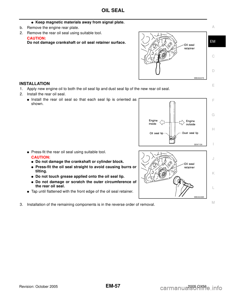
2. Remove the rear oil seal using suitable tool.
CAUTION:
Do not damage crankshaft or oil seal retainer surface.
INSTALLATION
1. Apply new engine oil to both the oil seal lip and dust seal lip of the new rear oil seal.
2. Install the rear oil seal.
�Install the rear oil seal so that each seal lip is oriented as
shown.
�Press-fit the rear oil seal using suitable tool.
CAUTION:
�Do not damage the crankshaft or cylinder block.
�Press-fit the oil seal straight to avoid causing burrs or
tilting.
�Do not touch grease applied onto the oil seal lip.
�Do not damage or scratch the outer circumference of
the rear oil seal.
�Tap until flattened with the front edge of the oil seal retainer.
3. Installation of the remaining components is in the reverse order of removal.
WBIA0437E
SEM 71 5A
WBIA0438E
Page 1963 of 3419

EM-60Revision: October 2005
CYLINDER HEAD
2005 QX56
INSPECTION AFTER REMOVAL
Cylinder Head Bolts Diameter
�Cylinder head bolts are tightened by plastic zone tightening
method. Whenever the size difference between d1 and d2
exceeds the limit, replace the bolt with a new one.
�If reduction of diameter appears in a position other than d2, use
it as d2 point.
INSTALLATION
1. Install a new cylinder head gasket.
2. Install the cylinder head. Follow the steps below to tighten the
bolts in the numerical order shown.
CAUTION:
�If cylinder head bolts are re-used, check their diameters
before installation. Refer to EM-60, "
Cylinder Head Bolts
Diameter" .
a. Apply engine oil to threads and seating surface of the bolts.
b. Measure the tightening angle using Tool.
CAUTION:
Measure the tightening angle using Tool. Do not measure
visually.
3. Installation of the remaining components is in the reverse order of removal.Limit (d1 - d2) : 0.18 mm (0.0071 in)
KBIA0189E
Step a : 98.1 N·m (10 kg-m, 72 ft-lb)
Step b :Loosen in the reverse order of tightening.
Step c : 44.1 N·m (4.5 kg-m, 33 ft-lb)
PBIC0068E
Tool number : KV10112100 (BT-8653-A)
Step d : 60° clockwise
Step e : 60° clockwise
WBIA0603E
Page 1973 of 3419

EM-70Revision: October 2005
ENGINE ASSEMBLY
2005 QX56
5. Remove the cowl extension. Refer to EI-18, "Removal and Installation" .
6. Remove the engine room cover using power tools.
7. Remove the air duct and air cleaner case assembly EM-14, "
REMOVAL" .
8. Disconnect the vacuum hose between the vehicle and engine and set it aside.
9. Remove the radiator assembly and hoses. Refer to CO-12, "
REMOVAL" .
10. Remove the drive belts. Refer to EM-12, "
Removal" .
11. Remove the fan blade. Refer to CO-15, "
REMOVAL" .
12. Disconnect the engine room harness from the fuse box and set it aside.
13. Disconnect the ECM.
14. Disconnect the engine room harness from the engine side and set it aside.
15. Disconnect the engine harness grounds.
16. Disconnect the power steering reservoir tank from the engine and move it aside.
17. Disconnect the power steering oil pump from the engine. Move it aside and secure it using suitable wire or
rope. Refer to PS-26, "
REMOVAL" .
18. Remove the A/C compressor bolts and set the compressor aside. Refer to ATC-179, "
REMOVAL" .
19. Disconnect the brake booster vacuum line.
20. Disconnect the EVAP line.
21. Disconnect the fuel hose at the engine side connection. Refer to EM-29, "
REMOVAL" .
22. Disconnect the heater hoses at cowl, and install plugs to avoid leakage of engine coolant.
23. Remove the A/T oil level indicator and indicator tube upper bolts.
24. Remove the front final drive assembly (4x4 only). Refer to FFD-11, "
REMOVAL" .
25. Remove the exhaust manifolds. Refer to EM-19, "
Removal and Installation" .
26. Install the engine slingers into the left bank cylinder head and
right bank cylinder head.
27. Remove the A/T. Refer to AT-244, "
Removal and Installation
(4x2)" or AT-247, "Removal and Installation (4x4)" .
28. Lift using hoist and secure the engine in position.
29. Remove the engine assembly from the vehicle, avoid interfer-
ence with the vehicle body.
CAUTION:
�Before and during lifting, always check if any harnesses
are left connected.
30. Remove the parts that may restrict installation of the engine to the engine stand.
NOTE:
This procedure is described assuming that you use an engine stand mounting to the surface to which the
transmission mounts.
a. Remove the drive plate.
�Holding the crankshaft pulley bolt, lock the crankshaft to remove the drive plate bolts.
�Loosen the bolts diagonally.
WBIA0464E
Engine slinger torque: 45.0 N·m (4.6 kg-m, 33 ft-lb)
PBIC1556E
Page 1976 of 3419
CYLINDER BLOCK
EM-73
C
D
E
F
G
H
I
J
K
L
MA
EM
Revision: October 20052005 QX56
CYLINDER BLOCKPFP:11010
Disassembly and AssemblyEBS00LMJ
WBIA0471E
Page 1977 of 3419

EM-74Revision: October 2005
CYLINDER BLOCK
2005 QX56
* Refer to GI-45, "Recommended Chemical Products and Sealants" .
DISASSEMBLY
NOTE:
Explained here is how to disassemble with engine stand supporting transmission surface. When using differ-
ent type of engine stand, note steps may be different.
1. Remove engine assembly and mount to engine stand. Refer to EM-69, "
REMOVAL" .
CAUTION:
Before removing the hanging chains, make sure engine stand is stable and there is no risk of over-
turning.
2. Drain engine oil. Refer to LU-8, "
Changing Engine Oil" .
3. Drain engine coolant by removing the cylinder block drain plugs
“A”, “B”, “C” and “D” as shown.
4. Remove the following components and associated parts (The parts referred to in step 1 are not included
here.)
�Oil pan and oil strainer. Refer to EM-22, "REMOVAL" .
�Crankshaft pulley, front cover and timing chain. Refer to EM-36, "REMOVAL" .
�Camshaft. Refer to EM-43, "REMOVAL" .
�Cylinder head. Refer to EM-59, "REMOVAL" .
5. Remove knock sensor.
CAUTION:
Carefully handle sensor, avoiding shocks.
6. Check connecting rod side clearance. Refer to EM-89, "
CONNECTING ROD SIDE CLEARANCE" .
7. Remove piston and connecting rod assembly as follows.
a. Position the crankshaft pin corresponding to the connecting rod to be removed onto bottom dead center.
b. Remove connecting rod cap.
1. Knock sensor sub-harness 2. Knock sensor 3. Cylinder block
4. Main bearing 5. Top ring 6. Second ring
7. Oil ring 8. Crankshaft key 9. Piston
10. Connecting rod 11. Snap ring 12. Piston pin
13. Connecting rod bearing 14. Connecting rod bearing cap 15. Main bearing cap
16. Thrust bearing 17. Main bearing 18. Crankshaft
19. Pilot converter 20. Thrust bearing 21. Side bolt
22. Drive plate 23. Reinforcement plate 24. Rear oil seal retainer
25. Rear oil seal 26. Transmission 27. O-ring
28. Crankshaft position sensor (POS) 29. Gasket 30. Cylinder block heater
31. Connector cap
WBIA0419E
Page 1978 of 3419
CYLINDER BLOCK
EM-75
C
D
E
F
G
H
I
J
K
L
MA
EM
Revision: October 20052005 QX56
c. Push the piston and connecting rod assembly out to the cylinder
head side using suitable tool.
8. Remove connecting rod bearings.
CAUTION:
When removing them, note the installation position. Keep them in the correct order.
9. Check piston ring side clearance. Refer to EM-90, "
PISTON RING SIDE CLEARANCE" .
10. Remove piston rings from piston using suitable tool.
CAUTION:
�Do not damage piston.
�Do not damage piston rings by expanding them exces-
sively.
11. Remove piston from connecting rod as follows.
a. Remove snap ring using suitable tool.
b. Heat the piston to 60° to 70°C (140° to 158°F) using suitable
tool.
PBIC0086E
PBIC0087E
PBIC0260E
PBIC0261E