Page 2069 of 3419
FL-4Revision: October 2005
FUEL SYSTEM
2005 QX56
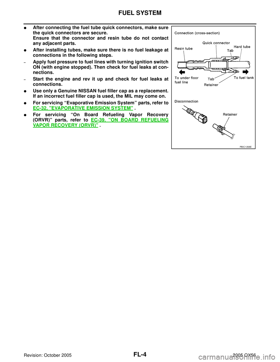
�After connecting the fuel tube quick connectors, make sure
the quick connectors are secure.
Ensure that the connector and resin tube do not contact
any adjacent parts.
�After installing tubes, make sure there is no fuel leakage at
connections in the following steps.
–Apply fuel pressure to fuel lines with turning ignition switch
ON (with engine stopped). Then check for fuel leaks at con-
nections.
–Start the engine and rev it up and check for fuel leaks at
connections.
�Use only a Genuine NISSAN fuel filler cap as a replacement.
If an incorrect fuel filler cap is used, the MIL may come on.
�For servicing “Evaporative Emission System” parts, refer to
EC-32, "
EVAPORATIVE EMISSION SYSTEM" .
�For servicing “On Board Refueling Vapor Recovery
(ORVR)” parts, refer to EC-39, "
ON BOARD REFUELING
VAPOR RECOVERY (ORVR)" .
PBIC1268E
Page 2070 of 3419

FUEL LEVEL SENSOR UNIT, FUEL FILTER AND FUEL PUMP ASSEMBLY
FL-5
C
D
E
F
G
H
I
J
K
L
MA
FL
Revision: October 20052005 QX56
FUEL LEVEL SENSOR UNIT, FUEL FILTER AND FUEL PUMP ASSEMBLYPFP:17042
Removal and InstallationEBS00M3S
REMOVAL
WA RN ING:
Follow the “General Precautions” before working on the fuel system. Refer to FL-3, "
General Precau-
tions" .
1. Remove the fuel filler cap to release the pressure from inside the fuel tank.
2. Check the fuel level on level gauge. If the fuel gauge indicates
more than the level as shown (full or almost full), drain the fuel
from the fuel tank until the fuel gauge indicates the level as
shown, or less.
�If the fuel pump does not operate, use the following procedure
to drain the fuel to the specified level.
a. Insert a suitable hose of less than 15 mm (0.59 in) diameter into
the fuel filler pipe through the fuel filler opening to drain the fuel
from fuel filler pipe.
b. Remove the LH rear wheel and tire. Refer to WT-7, "
Rotation" .
c. Remove the four clips and remove the rear fender protector,
front.
1. Inspection hole cover 2. Inspection hole cover O-ring 3. Lock ring
4. Fuel level sensor, fuel filter, and fuel
pump assembly5. Fuel tank 6. Fuel level sensor, fuel filter, and fuel
pump assembly O-ring
LBIA0381E
WBIA0390E
Page 2071 of 3419

FL-6Revision: October 2005
FUEL LEVEL SENSOR UNIT, FUEL FILTER AND FUEL PUMP ASSEMBLY
2005 QX56
d. Disconnect the fuel filler hose from the fuel filler pipe.
e. Insert a suitable hose into the fuel tank through the fuel filler hose to drain the fuel from the fuel tank.
�As a guide, the fuel level reaches the fuel gauge position as shown, or less, when approximately 14
liters (3 3/4 US gal, 3 1/8 Imp gal) of fuel are drained from the fuel tank.
3. Release the fuel pressure from the fuel lines. Refer to EC-93, "
FUEL PRESSURE RELEASE" .
4. Remove the second row LH rear seat and the third row rear seat. Refer to SE-104, "
REAR SEAT" .
5. Remove the second and third row rear seat belt buckles mounted on the floor. Refer to SB-3, "
SEAT
BELTS" .
6. Remove the LH center pillar trim, the LH rear trim panel, and the LH rear side door kick plate and weather
stripping. Refer to EI-35, "
BODY SIDE TRIM" .
7. Remove the second row rear center console and base, if equipped. Refer to EI-37, "
FLOOR TRIM" .
8. Reposition the floor carpet out of the way to access the inspection hole cover, located under the center LH
rear seat.
9. Remove the inspection hole cover by turning the retainers 90°
degrees clockwise.
�Remove the o-ring.
10. Disconnect the fuel level sensor, fuel filter, and fuel pump
assembly electrical connector, the EVAP hose, and the fuel feed
hose.
LBIA0386E
LBIA0382E
LBIA0383E
Page 2072 of 3419

FUEL LEVEL SENSOR UNIT, FUEL FILTER AND FUEL PUMP ASSEMBLY
FL-7
C
D
E
F
G
H
I
J
K
L
MA
FL
Revision: October 20052005 QX56
Disconnect the quick connector as follows:
�Hold the sides of the connector, push in tabs and pull out the
tube.
�If the connector and the tube are stuck together, push and pull
several times until they start to move. Then disconnect them
by pulling.
CAUTION:
�The quick connector can be disconnected when the tabs
are completely depressed. Do not twist the quick connec-
tor more than necessary.
�Do not use any tools to disconnect the quick connector.
�Keep the resin tube away from heat. Be especially careful
when welding near the tube.
�Prevent any acid liquids such as battery electrolyte, from
getting on the resin tube.
�Do not bend or twist the resin tube during connection.
�Do not remove the remaining retainer on the hard tube (or
the equivalent) except when the resin tube or the retainer
is replaced.
�When the resin tube or hard tube, or the equivalent, is
replaced, also replace the retainer with a new one (white
colored retainer).
�To keep the quick connector clean and to avoid damage
and contamination from foreign materials, cover the
quick connector with plastic bags or suitable material as
shown.
SF E5 62 A
PBIC1268E
PBIC0163E
Page 2073 of 3419

FL-8Revision: October 2005
FUEL LEVEL SENSOR UNIT, FUEL FILTER AND FUEL PUMP ASSEMBLY
2005 QX56
11. Remove the lock ring using Tool.
12. Remove the fuel level sensor, fuel filter, and fuel pump assem-
bly.
CAUTION:
�Do not bend the float arm during removal.
�Avoid impacts such as dropping when handling the com-
ponents.
INSTALLATION
Installation is in the reverse order of removal.
�Connect the quick connector as follows:
–Check the connection for any damage or foreign materials.
–Align the connector with the pipe, then insert the connector straight into the pipe until a click is heard.
–After connecting the quick connector, make sure that the con-
nection is secure by checking as follows:
–Pull the tube and the connector to make sure they are securely
connected.
–Visually inspect the connector to make sure the two retainer tabs
are securely connected.
INSPECTION AFTER INSTALLATION
1. Turn the ignition switch ON but do not start engine, then check the fuel pipes and hose connections for
leaks while applying fuel pressure to the system.
2. Start the engine and rev it above idle speed, then check that there are no fuel leaks at any of the fuel pipe
and hose connections.Tool number : — (J-46536)
LBIA0389E
PBIC1653E
Page 2074 of 3419
FUEL TANK
FL-9
C
D
E
F
G
H
I
J
K
L
MA
FL
Revision: October 20052005 QX56
FUEL TANKPFP:17202
Removal and InstallationEBS00M3T
1. Inspection hole cover 2. Inspection hole cover O-ring 3. Lock ring
4. Fuel level sensor, fuel filter, and fuel
pump assembly5. Fuel tank 6. Fuel tank protector
7. Fuel tank protector clips 8. Fuel tank straps 9. Fuel level sensor, fuel filter, and fuel
pump assembly O-ring
WBIA0443E
Page 2075 of 3419

FL-10Revision: October 2005
FUEL TANK
2005 QX56
REMOVAL
WAR NIN G:
Follow the “General Precautions” before working on the fuel system. Refer to FL-3, "
General Precau-
tions" .
1. Drain the fuel from the fuel tank, if necessary.
�Position the vehicle so it is level.
2. Remove the fuel filler cap to release the pressure from inside the fuel tank.
3. Check the fuel level on level gauge. If the fuel gauge indicates
more than the level as shown (full or almost full), drain the fuel
from the fuel tank until the fuel gauge indicates the level as
shown, or less.
�If the fuel pump does not operate, use the following procedure
to drain the fuel to the specified level after disconnecting the
fuel filler hose from the fuel filler pipe.
a. Insert a suitable hose of less than 15 mm (0.59 in) diameter into
the fuel filler pipe through the fuel filler opening to drain the fuel
from fuel filler pipe.
b. Insert a suitable hose into the fuel tank through the fuel filler
hose to drain the fuel from the fuel tank.
�As a guide, the fuel level reaches the fuel gauge position as shown, or less, when approximately 14
liters (3 3/4 US gal, 3 1/8 Imp gal) of fuel are drained from the fuel tank.
4. Remove the LH rear wheel and tire. Refer to WT-7, "
Rotation" .
5. Remove the four clips and remove the rear fender protector, front.
6. Disconnect the fuel filler hose from the fuel filler pipe and dis-
connect the vent hose quick connector.
7. Release the fuel pressure from the fuel lines. Refer to EC-93, "
FUEL PRESSURE RELEASE" .
8. Remove the second row LH rear seat and the third row rear seat. Refer to SE-104, "
REAR SEAT" .
9. Remove the second and third row rear seat belt buckles mounted on the floor. Refer to SB-3, "
SEAT
BELTS" .
10. Remove the LH center pillar trim, the LH rear trim panel, and the LH rear side door kick plate and weather
stripping. Refer to EI-35, "
BODY SIDE TRIM" .
11. Remove the second row rear center console and base. Refer to EI-37, "
FLOOR TRIM" .
12. Reposition the floor carpet out of the way to access the inspection hole cover, located under the center LH
rear seat.
10. Fuel filler hose 11. Fuel filler pipe 12. Fuel filler cup
13. Fuel filler hose grommet 14. Fuel filler cap 15. Fuel tank shield
WBIA0390E
LBIA0386E
Page 2076 of 3419
FUEL TANK
FL-11
C
D
E
F
G
H
I
J
K
L
MA
FL
Revision: October 20052005 QX56
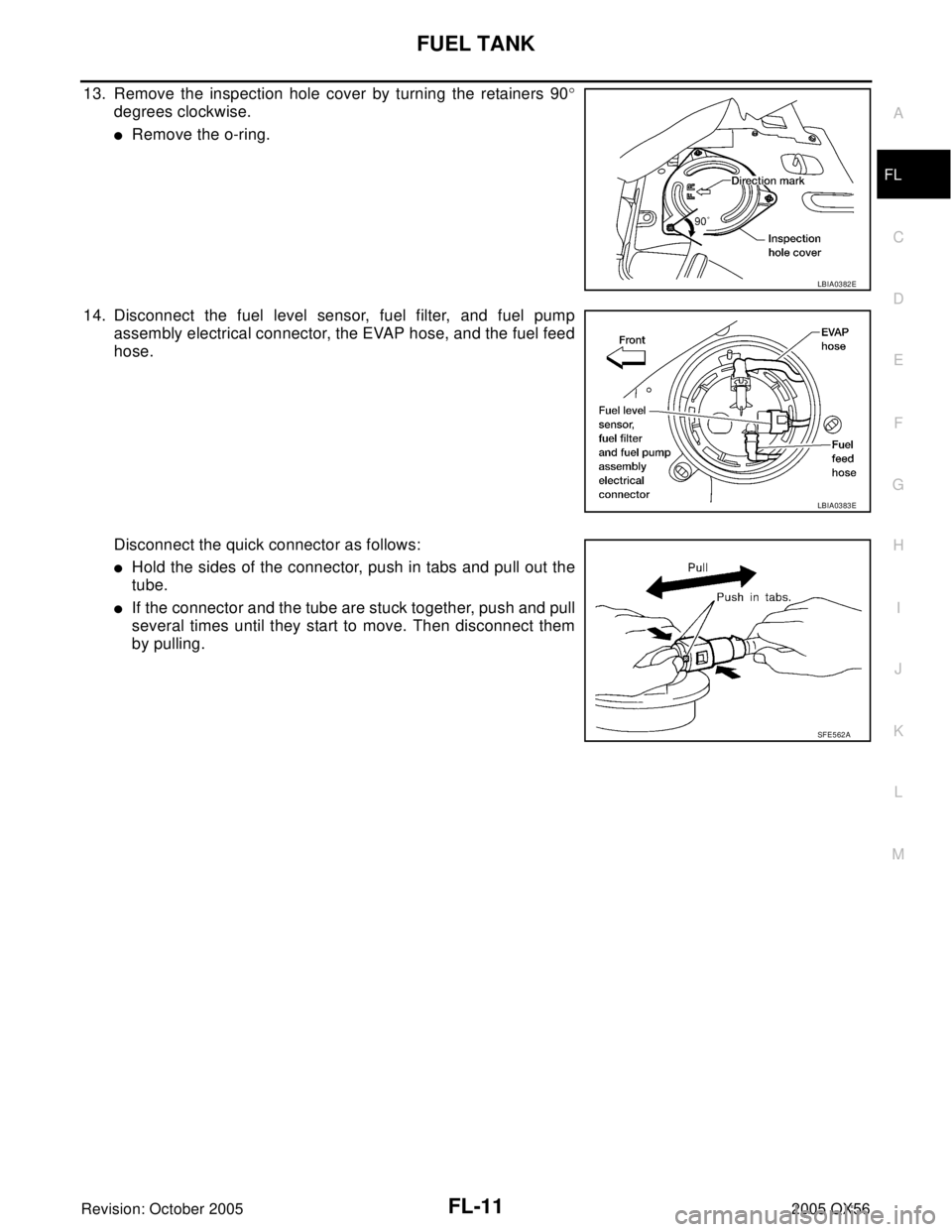
13. Remove the inspection hole cover by turning the retainers 90°
degrees clockwise.
�Remove the o-ring.
14. Disconnect the fuel level sensor, fuel filter, and fuel pump
assembly electrical connector, the EVAP hose, and the fuel feed
hose.
Disconnect the quick connector as follows:
�Hold the sides of the connector, push in tabs and pull out the
tube.
�If the connector and the tube are stuck together, push and pull
several times until they start to move. Then disconnect them
by pulling.
LBIA0382E
LBIA0383E
SF E5 62 A