Page 2022 of 3419
WHEEL HUB
FAX-5
C
E
F
G
H
I
J
K
L
MA
B
FA X
Revision: October 20052005 QX56
WHEEL HUBPFP:43202
On-Vehicle Inspection and ServiceEDS001XD
Make sure the mounting conditions (looseness, backlash) of each component and component status (wear,
damage) are normal.
WHEEL BEARING INSPECTION
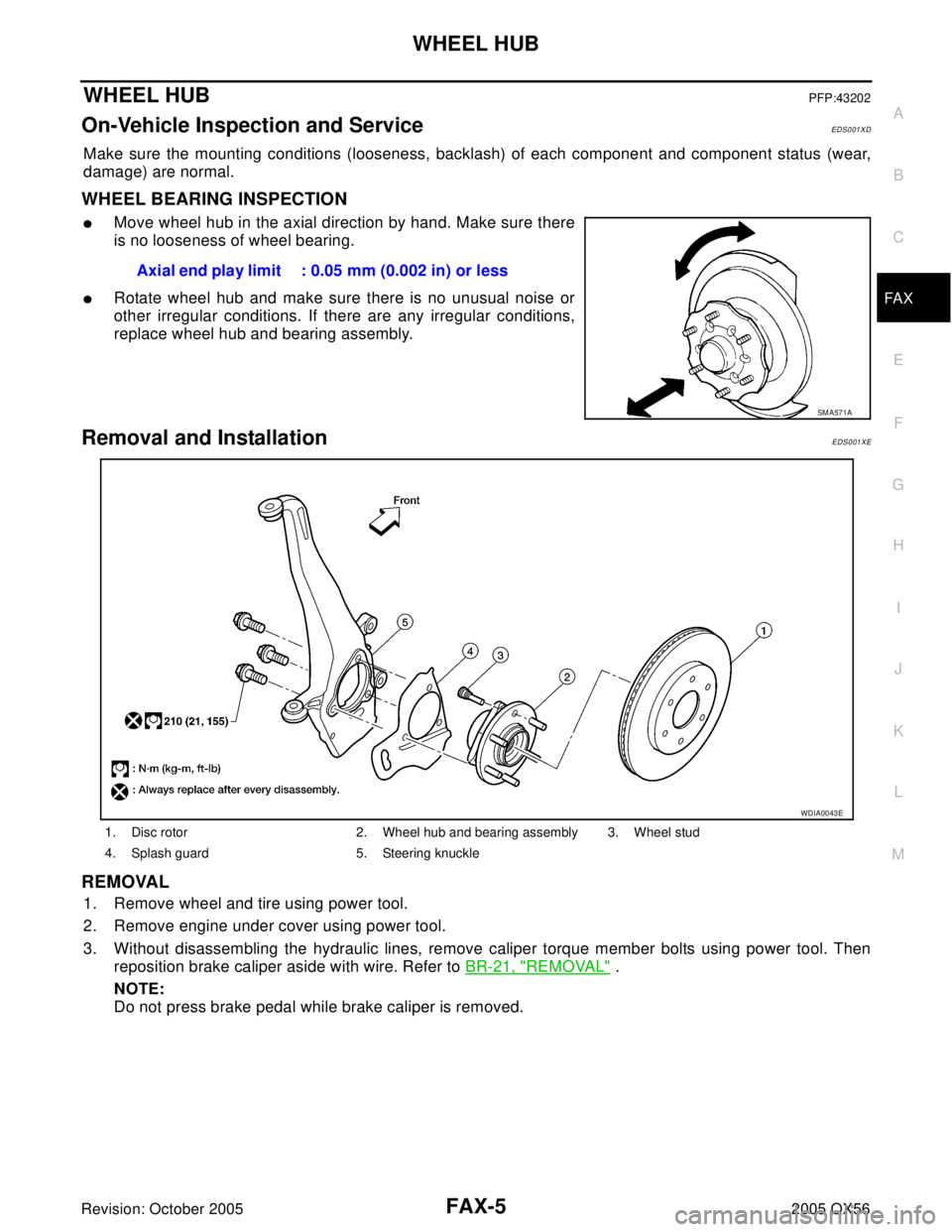
�Move wheel hub in the axial direction by hand. Make sure there
is no looseness of wheel bearing.
�Rotate wheel hub and make sure there is no unusual noise or
other irregular conditions. If there are any irregular conditions,
replace wheel hub and bearing assembly.
Removal and InstallationEDS001XE
REMOVAL
1. Remove wheel and tire using power tool.
2. Remove engine under cover using power tool.
3. Without disassembling the hydraulic lines, remove caliper torque member bolts using power tool. Then
reposition brake caliper aside with wire. Refer to BR-21, "
REMOVAL" .
NOTE:
Do not press brake pedal while brake caliper is removed.Axial end play limit : 0.05 mm (0.002 in) or less
SM A57 1A
1. Disc rotor 2. Wheel hub and bearing assembly 3. Wheel stud
4. Splash guard 5. Steering knuckle
WDIA0043E
Page 2030 of 3419
SERVICE DATA AND SPECIFICATIONS (SDS)
FAX-13
C
E
F
G
H
I
J
K
L
MA
B
FA X
Revision: October 20052005 QX56
SERVICE DATA AND SPECIFICATIONS (SDS)PFP:00030
Wheel BearingEDS001XH
Drive ShaftEDS001XI
Boot BandsEDS003M9
Unit: mm (in) Wheel bearing axial end play 0.05 mm (0.002 in) or less
Drive shaft joint typeFinal drive side Rzeppa
Wheel side Rzeppa
GreaseQualityNissan Genuine Grease or
equivalent
Capacity Final drive side 130 - 150 g (4.58 - 5.29 oz)
Wheel side 145 - 165 g (5.11 - 5.82 oz)
Boot length Final drive side "L " 145 mm (5.71 in)
Wheel side "L " 168.4 mm (6.63 in)
WDIA0055E
Dimension "M" 1.0 - 4.0 (0.39 - 1.57)
DSF0047D
Page 2031 of 3419
FAX-14
SERVICE DATA AND SPECIFICATIONS (SDS)
Revision: October 20052005 QX56
Page 2032 of 3419
FFD-1
FRONT FINAL DRIVE
D DRIVELINE/AXLE
CONTENTS
C
E
F
G
H
I
J
K
L
M
SECTION FFD
A
B
FFD
Revision: October 20052005 QX56 PRECAUTIONS .......................................................... 2
Precautions for Supplemental Restraint System
(SRS) “AIR BAG” and “SEAT BELT PRE-TEN-
SIONER” .................................................................. 2
Precautions .............................................................. 2
PREPARATION ........................................................... 3
Special Service Tools ............................................... 3
Commercial Service Tools ........................................ 5
NOISE, VIBRATION AND HARSHNESS (NVH)
TROUBLESHOOTING ................................................ 6
NVH Troubleshooting Chart ..................................... 6
FRONT OIL SEAL ...................................................... 7
Removal and Installation .......................................... 7
REMOVAL ............................................................. 7
INSTALLATION ..................................................... 8
SIDE OIL SEALS ........................................................ 9
Removal and Installation .......................................... 9
REMOVAL ............................................................. 9REAR COVER GASKET ........................................... 10
Removal and Installation ........................................ 10
REMOVAL ........................................................... 10
INSTALLATION ................................................... 10
FRONT FINAL DRIVE ASSEMBLY .......................... 11
Removal and Installation ........................................ 11
REMOVAL ........................................................... 11
INSTALLATION ................................................... 12
Disassembly and Assembly .................................... 13
COMPONENTS ................................................... 13
ASSEMBLY INSPECTION AND ADJUSTMENT ... 14
DISASSEMBLY ................................................... 17
INSPECTION AFTER DISASSEMBLY ................ 22
ADJUSTMENT AND SELECTION OF ADJUST-
ING WASHERS ................................................... 23
ASSEMBLY ......................................................... 24
SERVICE DATA AND SPECIFICATIONS (SDS) ...... 32
General Specifications ............................................ 32
Side Gear Adjustment ............................................ 32
Total Preload Adjustment ........................................ 32
Drive Pinion Height Adjustment .............................. 33
Page 2033 of 3419
FFD-2
PRECAUTIONS
Revision: October 20052005 QX56
PRECAUTIONSPFP:00001
Precautions for Supplemental Restraint System (SRS) “AIR BAG” and “SEAT
BELT PRE-TENSIONER”
EDS003PC
The Supplemental Restraint System such as “AIR BAG” and “SEAT BELT PRE-TENSIONER”, used along
with a front seat belt, helps to reduce the risk or severity of injury to the driver and front passenger for certain
types of collision. This system includes seat belt switch inputs and dual stage front air bag modules. The SRS
system uses the seat belt switches to determine the front air bag deployment, and may only deploy one front
air bag, depending on the severity of a collision and whether the front occupants are belted or unbelted.
Information necessary to service the system safely is included in the SRS and SB section of this Service Man-
ual.
WAR NIN G:
�To avoid rendering the SRS inoperative, which could increase the risk of personal injury or death
in the event of a collision which would result in air bag inflation, all maintenance must be per-
formed by an authorized NISSAN/INFINITI dealer.
�Improper maintenance, including incorrect removal and installation of the SRS, can lead to per-
sonal injury caused by unintentional activation of the system. For removal of Spiral Cable and Air
Bag Module, see the SRS section.
�Do not use electrical test equipment on any circuit related to the SRS unless instructed to in this
Service Manual. SRS wiring harnesses can be identified by yellow and/or orange harnesses or
harness connectors.
PrecautionsEDS003PD
CAUTION:
�Before starting diagnosis of the vehicle, understand symptoms well. Perform correct and system-
atic operations.
�Check for the correct installation status prior removal or disassembly. When matching marks are
required, be sure they do not interfere with the function of the parts they are applied to.
�Carry out an overhaul in a clean work place, Using a dust proof room is recommended.
�Before disassembly, using steam or white gasoline, completely remove sand and mud from the
exterior the unit, preventing them from entering into the unit during disassembly or assembly.
�Check appearance of the disassembled parts for damage, deformation, and abnormal wear. If a
malfunction is detected, replace it with a new one.
�Normally replace lock pins, oil seals, and bearings with new ones every times they are removed.
�In principle, tighten bolts or nuts gradually in several steps working diagonally from inside to out-
side. If tightening sequence is specified, observe it.
�Clean and flush the parts sufficiently and blow them dry.
�Be careful not to damage the sliding surfaces and mating surface.
�When applying sealant, remove the old sealant from the mounting surface; then remove any mois-
ture, oil, and foreign materials from the application and mounting surfaces.
�Always use shop paper for cleaning the inside of components.
�Avoid using cotton gloves or a shop cloth to prevent entering of lint.
�During assembly, observe the specified tightening torque, and new differential gear oil, Vaseline,
or multi-purpose grease, as specified for each vehicle, when necessary.
Page 2034 of 3419
PREPARATION
FFD-3
C
E
F
G
H
I
J
K
L
MA
B
FFD
Revision: October 20052005 QX56
PREPARATIONPFP:00002
Special Service ToolsEDS003PE
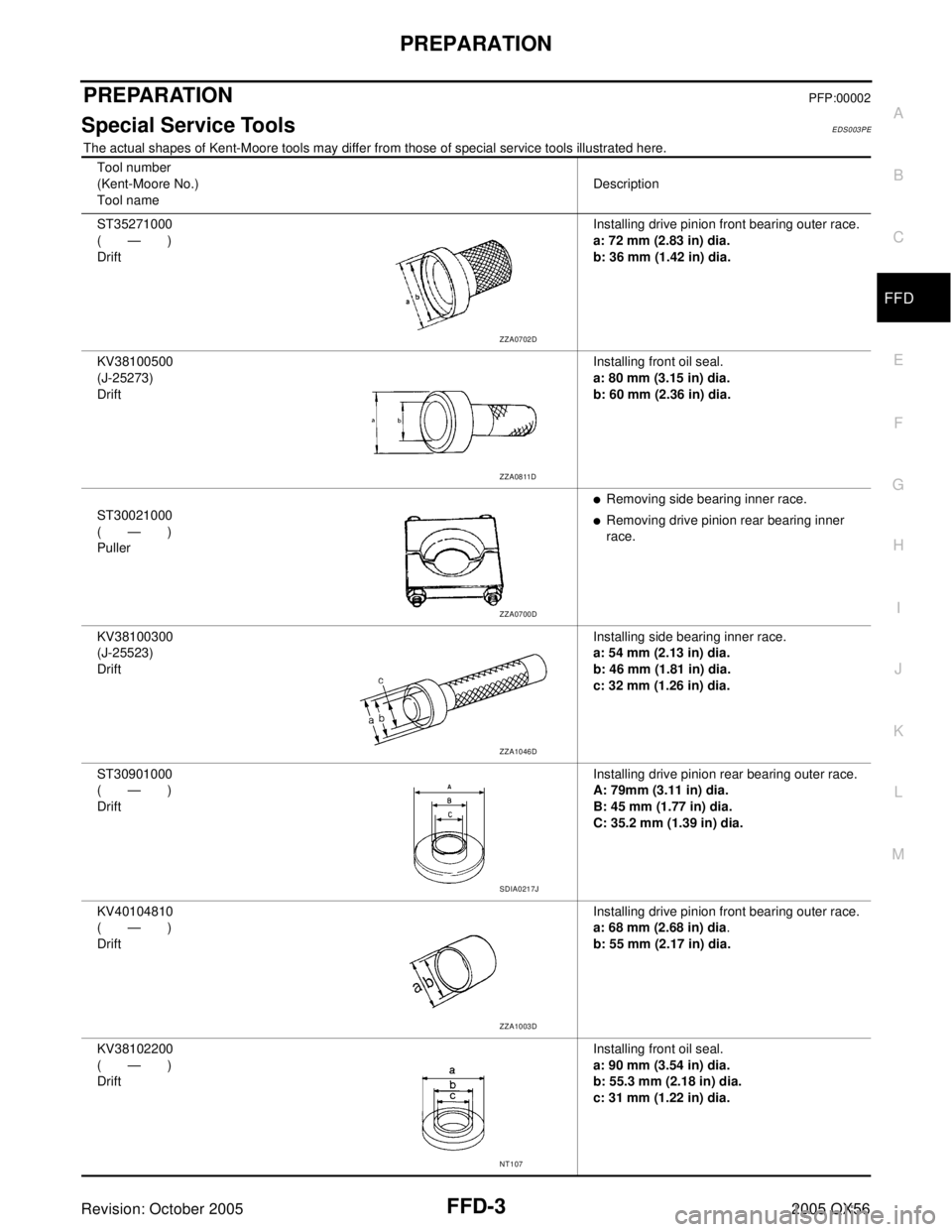
The actual shapes of Kent-Moore tools may differ from those of special service tools illustrated here.
Tool number
(Kent-Moore No.)
Tool nameDescription
ST35271000
(—)
DriftInstalling drive pinion front bearing outer race.
a: 72 mm (2.83 in) dia.
b: 36 mm (1.42 in) dia.
KV38100500
(J-25273)
DriftInstalling front oil seal.
a: 80 mm (3.15 in) dia.
b: 60 mm (2.36 in) dia.
ST30021000
(—)
Puller
�Removing side bearing inner race.
�Removing drive pinion rear bearing inner
race.
KV38100300
(J-25523)
DriftInstalling side bearing inner race.
a: 54 mm (2.13 in) dia.
b: 46 mm (1.81 in) dia.
c: 32 mm (1.26 in) dia.
ST30901000
(—)
DriftInstalling drive pinion rear bearing outer race.
A: 79mm (3.11 in) dia.
B: 45 mm (1.77 in) dia.
C: 35.2 mm (1.39 in) dia.
KV40104810
(—)
DriftInstalling drive pinion front bearing outer race.
a: 68 mm (2.68 in) dia.
b: 55 mm (2.17 in) dia.
KV38102200
(—)
DriftInstalling front oil seal.
a: 90 mm (3.54 in) dia.
b: 55.3 mm (2.18 in) dia.
c: 31 mm (1.22 in) dia.
ZZA0702D
ZZA0811D
ZZA0700D
ZZA1046D
SDIA0217J
ZZA1003D
NT107
Page 2036 of 3419
PREPARATION
FFD-5
C
E
F
G
H
I
J
K
L
MA
B
FFD
Revision: October 20052005 QX56
Commercial Service ToolsEDS003PF
—
(D-103)
RemoverRemoving drive pinion front bearing outer race
—
(C-4307)
RemoverRemoving drive pinion rear bearing outer race Tool number
(Kent-Moore No.)
Tool nameDescription
LDIA0135E
LDIA0135E
Tool nameDescription
Slide hammer
�Removing front oil seal
�Removing side oil seal
Power toolLoosening bolts and nuts
LDIA0133E
PBIC0190E
Page 2063 of 3419
FFD-32
SERVICE DATA AND SPECIFICATIONS (SDS)
Revision: October 20052005 QX56
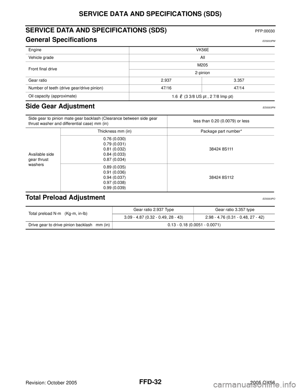
SERVICE DATA AND SPECIFICATIONS (SDS)PFP:00030
General SpecificationsEDS003PM
Side Gear AdjustmentEDS003PN
Total Preload AdjustmentEDS003PO
EngineVK56E
Vehicle gradeAll
Front final driveM205
2-pinion
Gear ratio 2.937 3.357
Number of teeth (drive gear/drive pinion) 47/16 47/14
Oil capacity (approximate)
1.6 (3 3/8 US pt , 2 7/8 Imp pt)
Side gear to pinion mate gear backlash (Clearance between side gear
thrust washer and differential case) mm (in)less than 0.20 (0.0079) or less
Available side
gear thrust
washersThickness mm (in) Package part number*
0.76 (0.030)
0.79 (0.031)
0.81 (0.032)
0.84 (0.033)
0.87 (0.034)38424 8S111
0.89 (0.035)
0.91 (0.036)
0.94 (0.037)
0.97 (0.038)
0.99 (0.039)38424 8S112
Total preload N·m (Kg-m, in-lb)Gear ratio 2.937 Type Gear ratio 3.357 type
3.09 - 4.87 (0.32 - 0.49, 28 - 43) 2.98 - 4.76 (0.31 - 0.48, 27 - 42)
Drive gear to drive pinion backlash mm (in) 0.13 - 0.18 (0.0051 - 0.0071)