Page 2010 of 3419

SERVICE DATA AND SPECIFICATIONS (SDS)
EM-107
C
D
E
F
G
H
I
J
K
L
MA
EM
Revision: October 20052005 QX56
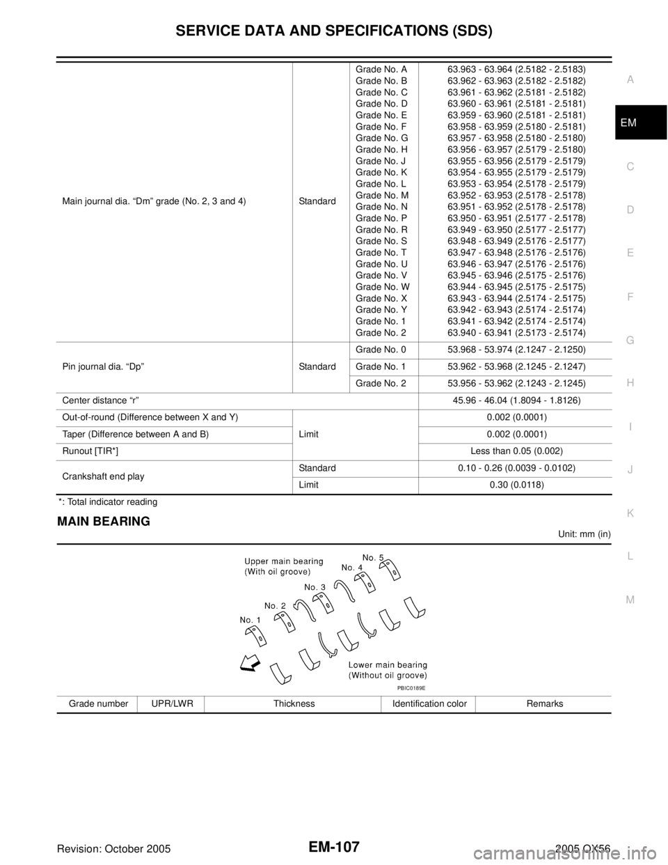
*: Total indicator reading
MAIN BEARING
Unit: mm (in) Main journal dia. “Dm” grade (No. 2, 3 and 4) StandardGrade No. A
Grade No. B
Grade No. C
Grade No. D
Grade No. E
Grade No. F
Grade No. G
Grade No. H
Grade No. J
Grade No. K
Grade No. L
Grade No. M
Grade No. N
Grade No. P
Grade No. R
Grade No. S
Grade No. T
Grade No. U
Grade No. V
Grade No. W
Grade No. X
Grade No. Y
Grade No. 1
Grade No. 263.963 - 63.964 (2.5182 - 2.5183)
63.962 - 63.963 (2.5182 - 2.5182)
63.961 - 63.962 (2.5181 - 2.5182)
63.960 - 63.961 (2.5181 - 2.5181)
63.959 - 63.960 (2.5181 - 2.5181)
63.958 - 63.959 (2.5180 - 2.5181)
63.957 - 63.958 (2.5180 - 2.5180)
63.956 - 63.957 (2.5179 - 2.5180)
63.955 - 63.956 (2.5179 - 2.5179)
63.954 - 63.955 (2.5179 - 2.5179)
63.953 - 63.954 (2.5178 - 2.5179)
63.952 - 63.953 (2.5178 - 2.5178)
63.951 - 63.952 (2.5178 - 2.5178)
63.950 - 63.951 (2.5177 - 2.5178)
63.949 - 63.950 (2.5177 - 2.5177)
63.948 - 63.949 (2.5176 - 2.5177)
63.947 - 63.948 (2.5176 - 2.5176)
63.946 - 63.947 (2.5176 - 2.5176)
63.945 - 63.946 (2.5175 - 2.5176)
63.944 - 63.945 (2.5175 - 2.5175)
63.943 - 63.944 (2.5174 - 2.5175)
63.942 - 63.943 (2.5174 - 2.5174)
63.941 - 63.942 (2.5174 - 2.5174)
63.940 - 63.941 (2.5173 - 2.5174)
Pin journal dia. “Dp” StandardGrade No. 0 53.968 - 53.974 (2.1247 - 2.1250)
Grade No. 1 53.962 - 53.968 (2.1245 - 2.1247)
Grade No. 2 53.956 - 53.962 (2.1243 - 2.1245)
Center distance “r”45.96 - 46.04 (1.8094 - 1.8126)
Out-of-round (Difference between X and Y)
Limit0.002 (0.0001)
Taper (Difference between A and B) 0.002 (0.0001)
Runout [TIR*]Less than 0.05 (0.002)
Crankshaft end playStandard 0.10 - 0.26 (0.0039 - 0.0102)
Limit 0.30 (0.0118)
Grade number UPR/LWR Thickness Identification color Remarks
PBIC0189E
Page 2011 of 3419

EM-108Revision: October 2005
SERVICE DATA AND SPECIFICATIONS (SDS)
2005 QX56
Undersize
Unit: mm (in)
Main Bearing Oil Clearance
Unit: mm (in)
Connecting Rod Bearing
Undersize
Unit: mm (in) 0 — 2.483 - 2.486 (0.0978 - 0.0979) Black
Grade is the same for upper
and lower bearings 1 — 2.486 - 2.489 (0.0979 - 0.0980) Brown
2 — 2.489 - 2.492 (0.0980 - 0.0981) Green
3 — 2.492 - 2.495 (0.0981 - 0.0982) Yellow
4 — 2.495 - 2.498 (0.0982 - 0.0983) Blue
5 — 2.498 - 2.501 (0.0983 - 0.0985) Pink
6 — 2.501 - 2.504 (0.0985 - 0.0986) Purple
7 — 2.504 - 2.507 (0.0986 - 0.0987) White
8 — 2.507 - 2.510 (0.0987 - 0.0988) Red
01UPR 2.483 - 2.486 (0.0978 - 0.0979) Black
Grade is different for upper
and lower bearings. LWR 2.486 - 2.489 (0.0979 - 0.0980) Brown
12UPR 2.486 - 2.489 (0.0979 - 0.0980) Brown
LWR 2.489 - 2.492 (0.0980 - 0.0981) Green
23UPR 2.489 - 2.492 (0.0980 - 0.0981) Green
LWR 2.492 - 2.495 (0.0981 - 0.0982) Yellow
34UPR 2.492 - 2.495 (0.0981 - 0.0982) Yellow
LWR 2.495 - 2.498 (0.0982 - 0.0983) Blue
45UPR 2.495 - 2.498 (0.0982 - 0.0983) Blue
LWR 2.498 - 2.501 (0.0983 - 0.0985) Pink
56UPR 2.498 - 2.501 (0.0983 - 0.0985) Pink
LWR 2.501 - 2.504 (0.0985 - 0.0986) Purple
67UPR 2.501 - 2.504 (0.0985 - 0.0986) Purple
LWR 2.504 - 2.507 (0.0986 - 0.0987) White
78UPR 2.504 - 2.507 (0.0986 - 0.0987) White
LWR 2.507 - 2.510 (0.0987 - 0.0988) Red
Undersize Thickness Main journal diameter
0.25 (0.0098) 2.618 - 2.626 (0.1031 - 0.1034) Grind so that bearing clearance is the specified value.
Items Standard Limit
Main bearing oil clearanceNo.1 and 5 0.001 - 0.011 (0.00004 - 0.0004) 0.021 (0.0008)
No.2, 3 and 4 0.007 - 0.017 (0.0003 - 0.0007) 0.027 (0.0011)
Grade number Thickness “T” mm (in) Identification color (mark)
0 1.500 - 1.503 (0.0591 - 0.0592) Black
1 1.503 - 1.506 (0.0592 - 0.0593) Brown
2 1.506 - 1.509 (0.0593 - 0.0594) Green
3 1.509 - 1.512 (0.0594 - 0.0595) Yellow
Undersize Thickness Crank pin journal diameter “Dp”
0.25 (0.0098) 1.627 - 1.635 (0.0641 - 0.0644) Grind so that bearing clearance is the specified value.
Page 2012 of 3419
SERVICE DATA AND SPECIFICATIONS (SDS)
EM-109
C
D
E
F
G
H
I
J
K
L
MA
EM
Revision: October 20052005 QX56
Connecting Rod Bearing Oil Clearance
Unit: mm (in)
Items Standard Limit
Connecting rod bearing oil clearance 0.020 - 0.039 (0.0008 - 0.0015) 0.055 (0.0022)
Page 2013 of 3419
EM-110Revision: October 2005
SERVICE DATA AND SPECIFICATIONS (SDS)
2005 QX56
Page 2014 of 3419
EX-1
EXHAUST SYSTEM
B ENGINE
CONTENTS
C
D
E
F
G
H
I
J
K
L
M
SECTION EX
A
EX
Revision: October 20052005 QX56 PREPARATION ........................................................... 2
Special Service Tool ................................................. 2
Commercial Service Tools ........................................ 2
EXHAUST SYSTEM ................................................... 3Checking Exhaust System ........................................ 3
Removal and Installation .......................................... 3
REMOVAL ............................................................. 4
INSTALLATION ..................................................... 4
INSPECTION AFTER INSTALLATION .................. 4
Page 2015 of 3419

EX-2Revision: October 2005
PREPARATION
2005 QX56
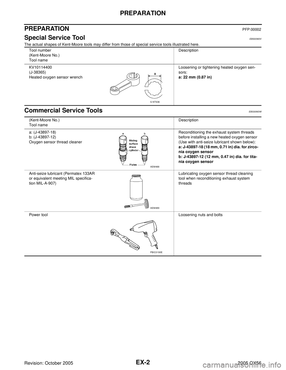
PREPARATIONPFP:00002
Special Service ToolEBS00M3V
The actual shapes of Kent-Moore tools may differ from those of special service tools illustrated here.
Commercial Service ToolsEBS00M3W
Tool number
(Kent-Moore No.)
Tool nameDescription
KV10114400
(J-38365)
Heated oxygen sensor wrenchLoosening or tightening heated oxygen sen-
sors:
a: 22 mm (0.87 in)
S-NT636
(Kent-Moore No.)
Tool nameDescription
a: (J-43897-18)
b: (J-43897-12)
Oxygen sensor thread cleanerReconditioning the exhaust system threads
before installing a new heated oxygen sensor
(Use with anti-seize lubricant shown below):
a: J-43897-18 (18 mm, 0.71 in) dia. for zirco-
nia oxygen sensor
b: J-43897-12 (12 mm, 0.47 in) dia. for tita-
nia oxygen sensor
Anti-seize lubricant (Permatex 133AR
or equivalent meeting MIL specifica-
tion MIL-A-907)Lubricating oxygen sensor thread cleaning
tool when reconditioning exhaust system
threads
Power toolLoosening nuts and bolts
AEM488
AEM489
PBIC0190E
Page 2018 of 3419

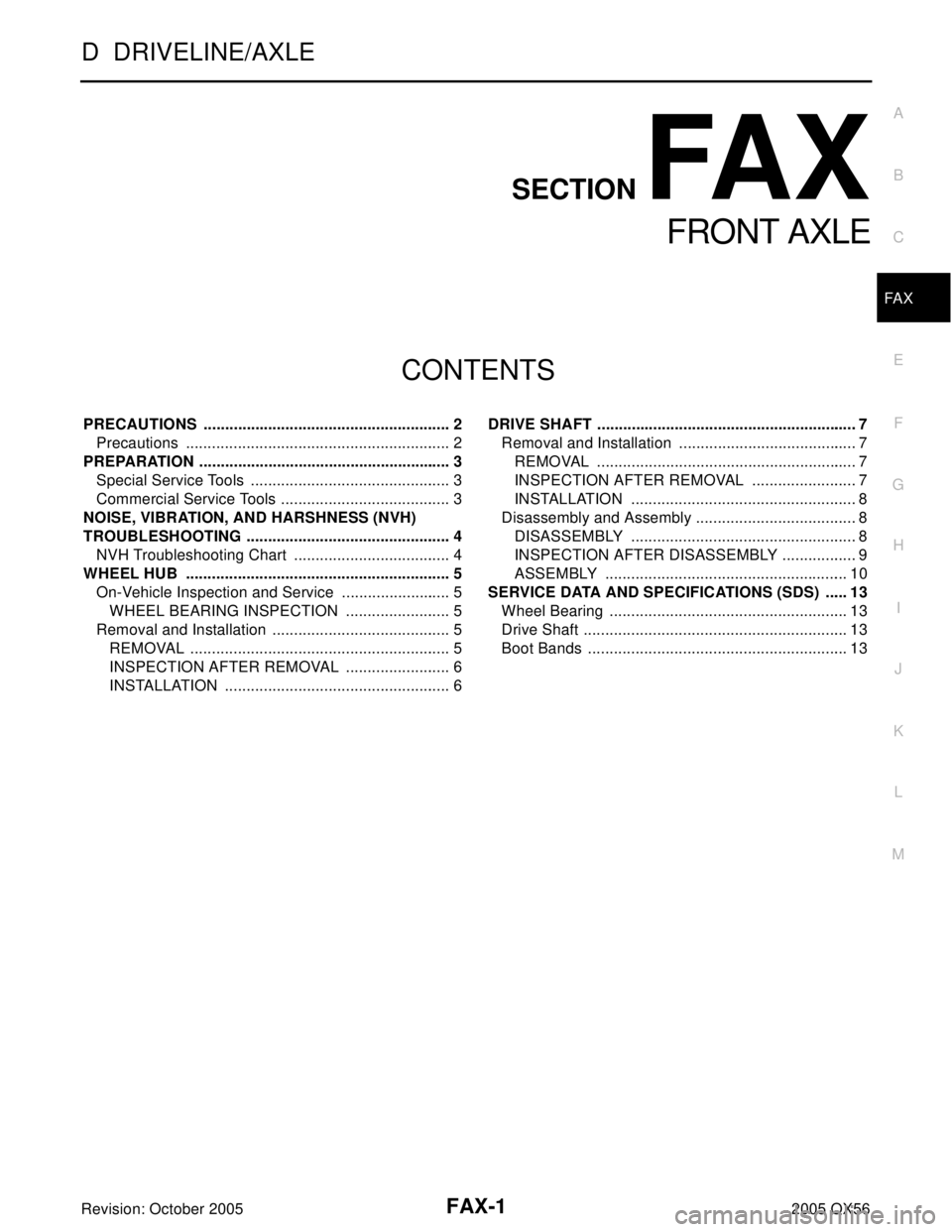
FAX-1
FRONT AXLE
D DRIVELINE/AXLE
CONTENTS
C
E
F
G
H
I
J
K
L
M
SECTION FA X
A
B
FA X
Revision: October 20052005 QX56 PRECAUTIONS .......................................................... 2
Precautions .............................................................. 2
PREPARATION ........................................................... 3
Special Service Tools ............................................... 3
Commercial Service Tools ........................................ 3
NOISE, VIBRATION, AND HARSHNESS (NVH)
TROUBLESHOOTING ................................................ 4
NVH Troubleshooting Chart ..................................... 4
WHEEL HUB .............................................................. 5
On-Vehicle Inspection and Service .......................... 5
WHEEL BEARING INSPECTION ......................... 5
Removal and Installation .......................................... 5
REMOVAL ............................................................. 5
INSPECTION AFTER REMOVAL ......................... 6
INSTALLATION ..................................................... 6DRIVE SHAFT ............................................................. 7
Removal and Installation .......................................... 7
REMOVAL ............................................................. 7
INSPECTION AFTER REMOVAL ......................... 7
INSTALLATION ..................................................... 8
Disassembly and Assembly ...................................... 8
DISASSEMBLY ..................................................... 8
INSPECTION AFTER DISASSEMBLY .................. 9
ASSEMBLY ......................................................... 10
SERVICE DATA AND SPECIFICATIONS (SDS) ...... 13
Wheel Bearing ........................................................ 13
Drive Shaft .............................................................. 13
Boot Bands ............................................................. 13
Page 2020 of 3419
PREPARATION
FAX-3
C
E
F
G
H
I
J
K
L
MA
B
FA X
Revision: October 20052005 QX56
PREPARATIONPFP:00002
Special Service ToolsEDS001XA
The actual shapes of Kent-Moore tools may differ from those of special service tools illustrated here.
Commercial Service Tools EDS001XB
Tool number
(Kent-Moore No.)
Tool nameDescription
ST29020001
(J-24319-01)
Gear arm pullerRemoving ball joint for steering knuckle
a: 34 mm (1.34 in)
b: 6.5 mm (0.256 in)
c: 61.5 mm (2.421 in)
KV40107300
(—)
Boot band crimping toolInstalling boot bands
NT694
ZZA1229D
Tool nameDescription
Power toolsRemoving bolts and nuts
PBIC0190E