Page 2824 of 3419
SQUEAK AND RATTLE TROUBLE DIAGNOSES
RF-7
C
D
E
F
G
H
J
K
L
MA
B
RF
Revision: October 20052005 QX56
TRUNK
Trunk noises are often caused by a loose jack or loose items put into the trunk by the owner.
In addition look for:
1. Trunk lid bumpers out of adjustment
2. Trunk lid striker out of adjustment
3. The trunk lid torsion bars knocking together
4. A loose license plate or bracket
Most of these incidents can be repaired by adjusting, securing or insulating the item(s) or component(s) caus-
ing the noise.
SUNROOF/HEADLINING
Noises in the sunroof/headlining area can often be traced to one of the following:
1. Sunroof lid, rail, linkage or seals making a rattle or light knocking noise
2. Sun visor shaft shaking in the holder
3. Front or rear windshield touching headliner and squeaking
Again, pressing on the components to stop the noise while duplicating the conditions can isolate most of these
incidents. Repairs usually consist of insulating with felt cloth tape.
OVERHEAD CONSOLE (FRONT AND REAR)
Overhead console noises are often caused by the console panel clips not being engaged correctly. Most of
these incidents are repaired by pushing up on the console at the clip locations until the clips engage.
In addition look for:
1. Loose harness or harness connectors.
2. Front console map/reading lamp lens loose.
3. Loose screws at console attachment points.
SEATS
When isolating seat noise it's important to note the position the seat is in and the load placed on the seat when
the noise is present. These conditions should be duplicated when verifying and isolating the cause of the
noise.
Cause of seat noise include:
1. Headrest rods and holder
2. A squeak between the seat pad cushion and frame
3. The rear seatback lock and bracket
These noises can be isolated by moving or pressing on the suspected components while duplicating the con-
ditions under which the noise occurs. Most of these incidents can be repaired by repositioning the component
or applying urethane tape to the contact area.
UNDERHOOD
Some interior noise may be caused by components under the hood or on the engine wall. The noise is then
transmitted into the passenger compartment.
Causes of transmitted underhood noise include:
1. Any component mounted to the engine wall
2. Components that pass through the engine wall
3. Engine wall mounts and connectors
4. Loose radiator mounting pins
5. Hood bumpers out of adjustment
6. Hood striker out of adjustment
These noises can be difficult to isolate since they cannot be reached from the interior of the vehicle. The best
method is to secure, move or insulate one component at a time and test drive the vehicle. Also, engine RPM
or load can be changed to isolate the noise. Repairs can usually be made by moving, adjusting, securing, or
insulating the component causing the noise.
Page 2833 of 3419
RF-16
SUNROOF
Revision: October 20052005 QX56
CONSULT-II Function (BCM)EIS004VW
CONSULT-II can display each diagnostic item using the diagnostic test modes shown following.
CONSULT-II OPERATION
CAUTION:
If CONSULT-II is used with no connection of CONSULT-II CONVERTER, malfunctions might be
detected in self-diagnosis depending on control unit which carries out CAN communication.
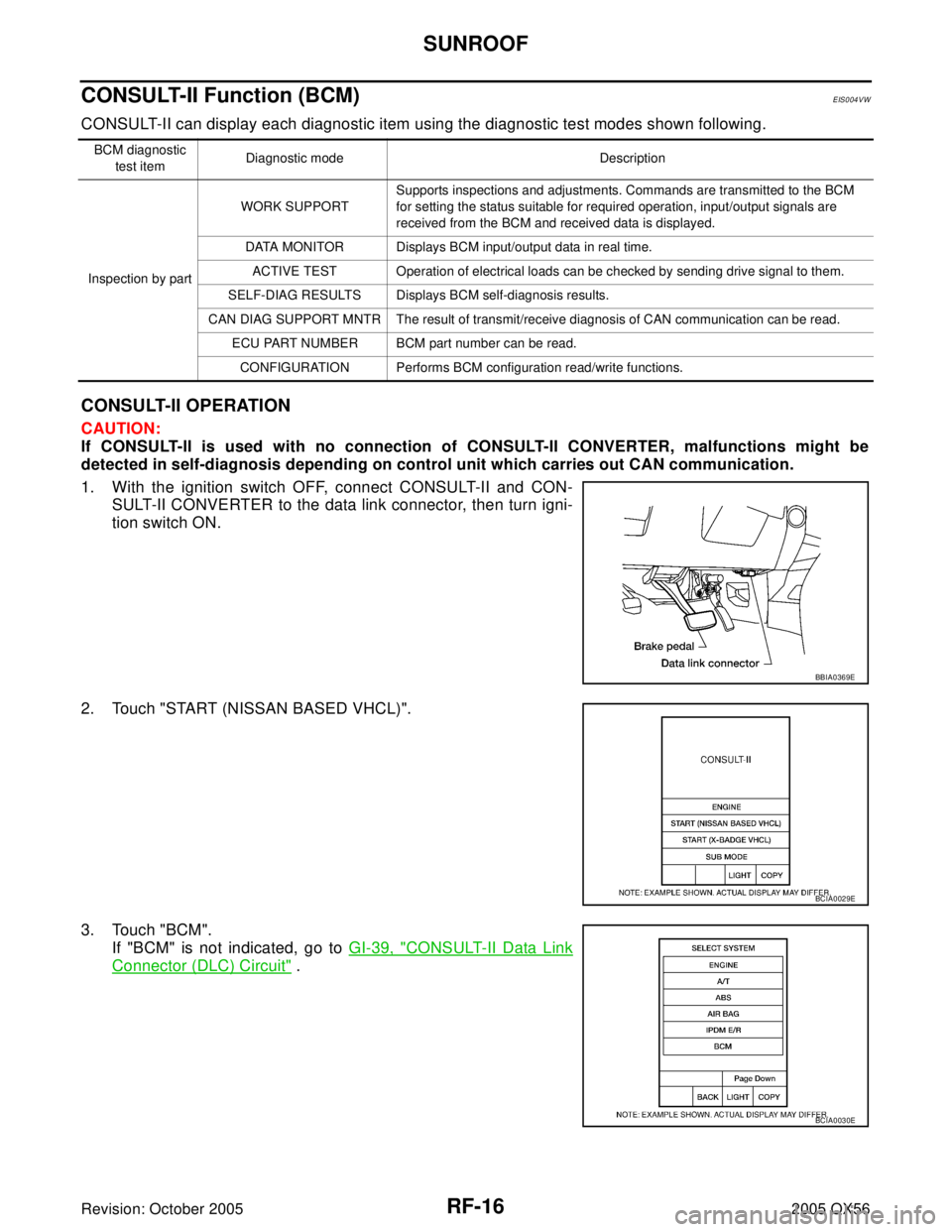
1. With the ignition switch OFF, connect CONSULT-II and CON-
SULT-II CONVERTER to the data link connector, then turn igni-
tion switch ON.
2. Touch "START (NISSAN BASED VHCL)".
3. Touch "BCM".
If "BCM" is not indicated, go to GI-39, "
CONSULT-II Data Link
Connector (DLC) Circuit" .
BCM diagnostic
test itemDiagnostic mode Description
Inspection by partWORK SUPPORTSupports inspections and adjustments. Commands are transmitted to the BCM
for setting the status suitable for required operation, input/output signals are
received from the BCM and received data is displayed.
DATA MONITOR Displays BCM input/output data in real time.
ACTIVE TEST Operation of electrical loads can be checked by sending drive signal to them.
SELF-DIAG RESULTS Displays BCM self-diagnosis results.
CAN DIAG SUPPORT MNTR The result of transmit/receive diagnosis of CAN communication can be read.
ECU PART NUMBER BCM part number can be read.
CONFIGURATION Performs BCM configuration read/write functions.
BBIA0369E
BCIA0029E
BCIA0030E
Page 2840 of 3419
SUNROOF
RF-23
C
D
E
F
G
H
J
K
L
MA
B
RF
Revision: October 20052005 QX56
Fitting AdjustmentEIS004W5
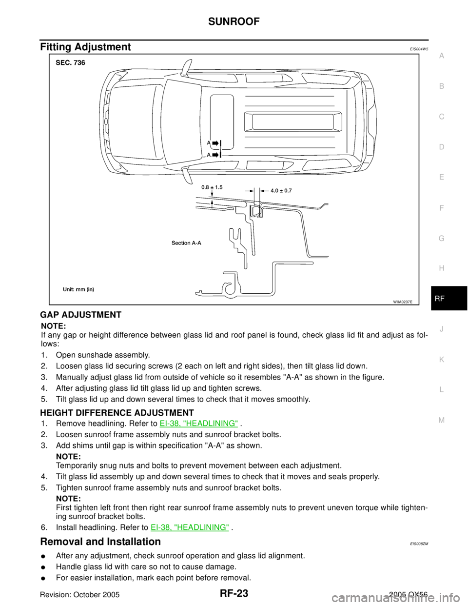
GAP ADJUSTMENT
NOTE:
If any gap or height difference between glass lid and roof panel is found, check glass lid fit and adjust as fol-
lows:
1. Open sunshade assembly.
2. Loosen glass lid securing screws (2 each on left and right sides), then tilt glass lid down.
3. Manually adjust glass lid from outside of vehicle so it resembles "A-A" as shown in the figure.
4. After adjusting glass lid tilt glass lid up and tighten screws.
5. Tilt glass lid up and down several times to check that it moves smoothly.
HEIGHT DIFFERENCE ADJUSTMENT
1. Remove headlining. Refer to EI-38, "HEADLINING" .
2. Loosen sunroof frame assembly nuts and sunroof bracket bolts.
3. Add shims until gap is within specification "A-A" as shown.
NOTE:
Temporarily snug nuts and bolts to prevent movement between each adjustment.
4. Tilt glass lid assembly up and down several times to check that it moves and seals properly.
5. Tighten sunroof frame assembly nuts and sunroof bracket bolts.
NOTE:
First tighten left front then right rear sunroof frame assembly nuts to prevent uneven torque while tighten-
ing sunroof bracket bolts.
6. Install headlining. Refer to EI-38, "
HEADLINING" .
Removal and InstallationEIS008ZM
�After any adjustment, check sunroof operation and glass lid alignment.
�Handle glass lid with care so not to cause damage.
�For easier installation, mark each point before removal.
WIIA0237E
Page 2843 of 3419
RF-26
SUNROOF
Revision: October 20052005 QX56
SUNROOF UNIT
Removal
CAUTION:
�Always work with a helper.
�When taking sunroof unit out, use shop cloths to protect the seats and trim from damage.
�After installing the sunroof unit and glass lid, be sure to check gap adjustment to ensure there is
no malfunction.
1. Remove headlining. Refer to EI-38, "
HEADLINING" .
2. Remove the sunroof glass lid. Refer to RF-26, "
GLASS LID" .
3. Remove overhead console bracket.
4. Disconnect the drain hoses.
5. Remove front sunroof bolts.
6. Remove rear sunroof bracket bolts.
7. Remove the side bolts and the sunroof unit.
Installation
1. Position the sunroof frame assembly and install the side bolts.
2. Install the rear brackets.
3. Install the front mounting bolts.
4. Connect drain hoses.
5. Install the overhead console bracket.
6. Install the sunroof glass lid. Refer to RF-26, "
GLASS LID" .
7. Install headlining. Refer to EI-38, "
HEADLINING" .
GLASS LID
Removal
1. Open sunshade.
2. Ensure glass lid is closed.
3. Remove side cover LH and RH.
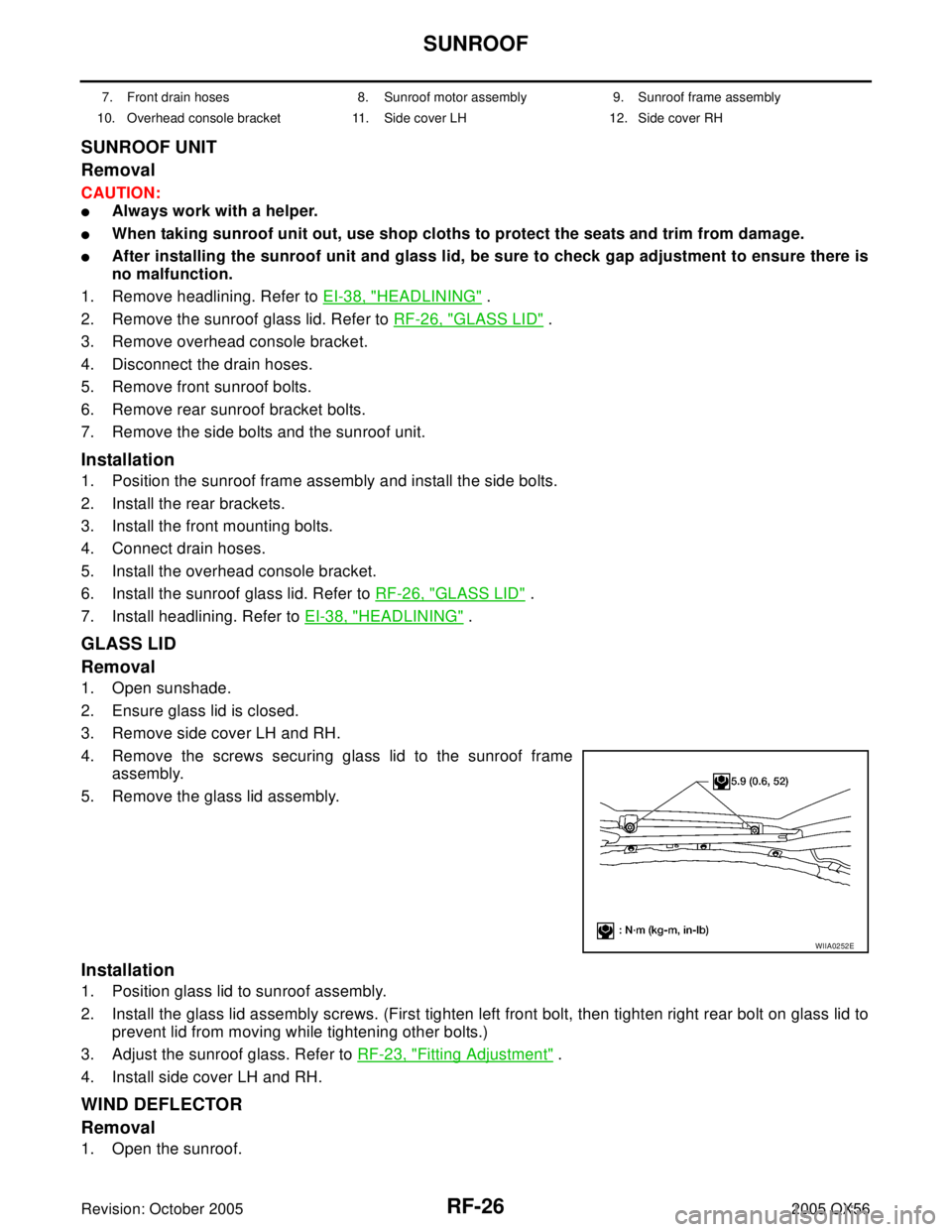
4. Remove the screws securing glass lid to the sunroof frame
assembly.
5. Remove the glass lid assembly.
Installation
1. Position glass lid to sunroof assembly.
2. Install the glass lid assembly screws. (First tighten left front bolt, then tighten right rear bolt on glass lid to
prevent lid from moving while tightening other bolts.)
3. Adjust the sunroof glass. Refer to RF-23, "
Fitting Adjustment" .
4. Install side cover LH and RH.
WIND DEFLECTOR
Removal
1. Open the sunroof.
7. Front drain hoses 8. Sunroof motor assembly 9. Sunroof frame assembly
10. Overhead console bracket 11. Side cover LH 12. Side cover RH
WIIA0252E
Page 2845 of 3419
RF-28
SUNROOF
Revision: October 20052005 QX56
1. Move the sunroof motor assembly laterally little by little so that
the gear is completely engaged into the wire on the sunroof unit
and the mounting surface becomes parallel. Then secure the
motor with bolts.
2. Connect the wire harness connector to the sunroof motor
assembly.
3. Install the roof console assembly. Refer to EI-38, "
HEADLINING" .
4. Reset the sunroof motor memory. Refer to RF-11, "
MEMORY RESET PROCEDURE" .
DRAIN HOSES
LIIA0270E
1. Rear drain hoses 2. Front drain hoses
WIIA0853E
Page 2888 of 3419
TROUBLE DIAGNOSIS
RSU-13
C
D
F
G
H
I
J
K
L
MA
B
RSU
Revision: October 20052005 QX56
CONSULT-II Function (AIR LEVELIZER)EES001H9
CONSULT-II can display each diagnostic item using the diagnostic test modes shown following.
CONSULT-II BASIC OPERATION PROCEDURE
CAUTION:
If CONSULT-II is used with no connection of CONSULT-II CONVERTER, malfunctions might be
detected in self-diagnosis depending on control unit which carries out CAN communication.
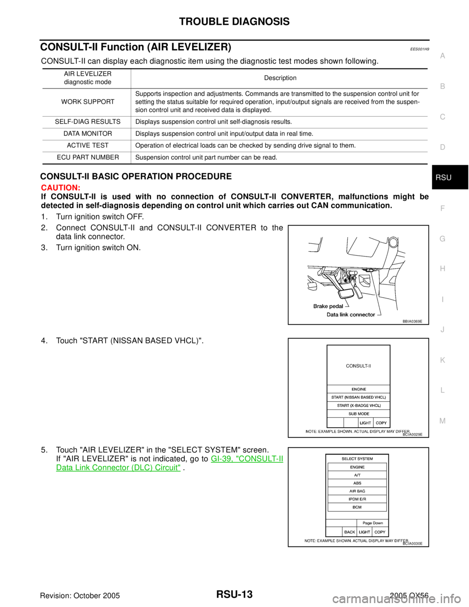
1. Turn ignition switch OFF.
2. Connect CONSULT-II and CONSULT-II CONVERTER to the
data link connector.
3. Turn ignition switch ON.
4. Touch "START (NISSAN BASED VHCL)".
5. Touch "AIR LEVELIZER" in the "SELECT SYSTEM" screen.
If "AIR LEVELIZER" is not indicated, go to GI-39, "
CONSULT-II
Data Link Connector (DLC) Circuit" .
AIR LEVELIZER
diagnostic modeDescription
WORK SUPPORTSupports inspection and adjustments. Commands are transmitted to the suspension control unit for
setting the status suitable for required operation, input/output signals are received from the suspen-
sion control unit and received data is displayed.
SELF-DIAG RESULTS Displays suspension control unit self-diagnosis results.
DATA MONITOR Displays suspension control unit input/output data in real time.
ACTIVE TEST Operation of electrical loads can be checked by sending drive signal to them.
ECU PART NUMBER Suspension control unit part number can be read.
BBIA0369E
BCIA0029E
BCIA0030E
Page 2908 of 3419
REAR SUSPENSION MEMBER
RSU-33
C
D
F
G
H
I
J
K
L
MA
B
RSU
Revision: October 20052005 QX56
INSTALLATION
Installation is in the reverse order of removal.
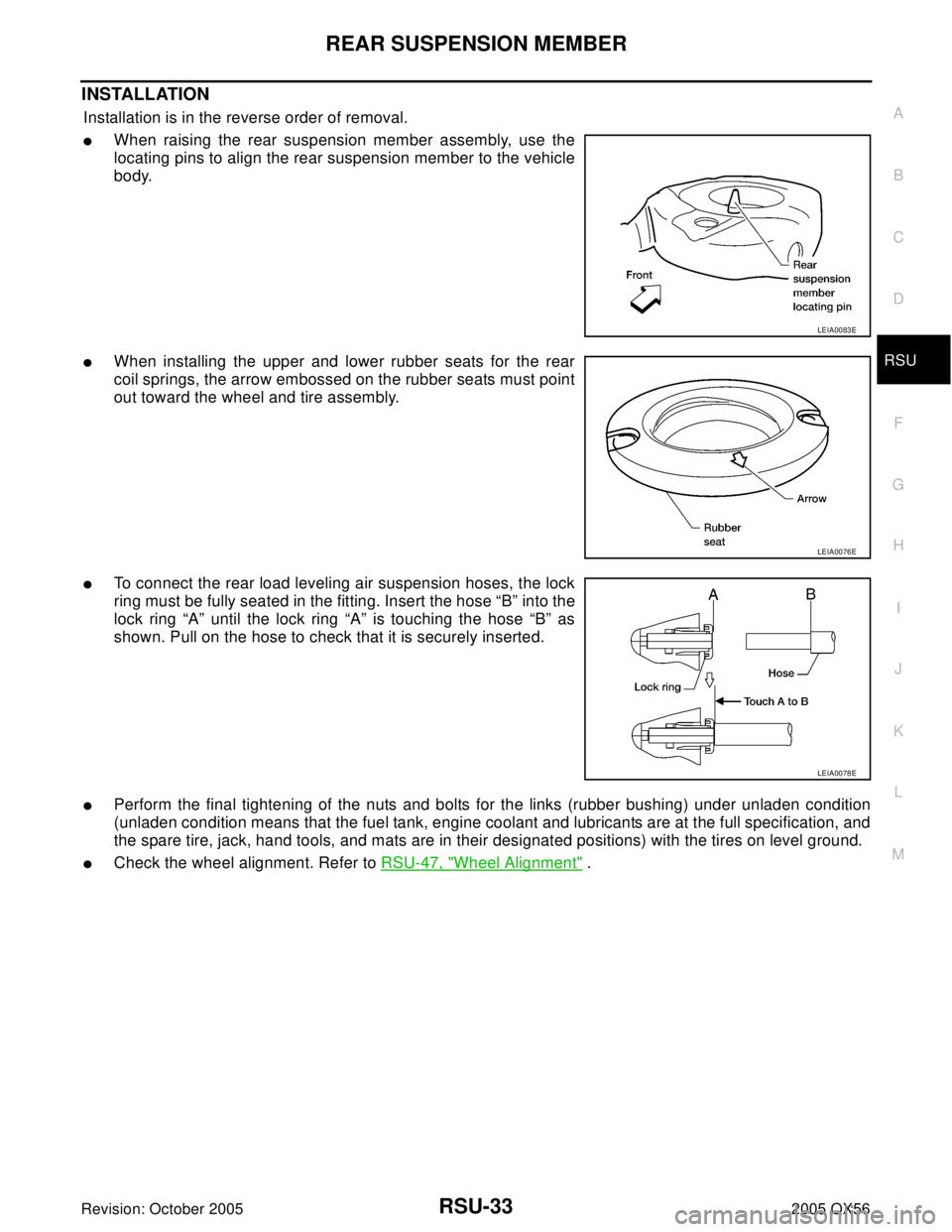
�When raising the rear suspension member assembly, use the
locating pins to align the rear suspension member to the vehicle
body.
�When installing the upper and lower rubber seats for the rear
coil springs, the arrow embossed on the rubber seats must point
out toward the wheel and tire assembly.
�To connect the rear load leveling air suspension hoses, the lock
ring must be fully seated in the fitting. Insert the hose “B” into the
lock ring “A” until the lock ring “A” is touching the hose “B” as
shown. Pull on the hose to check that it is securely inserted.
�Perform the final tightening of the nuts and bolts for the links (rubber bushing) under unladen condition
(unladen condition means that the fuel tank, engine coolant and lubricants are at the full specification, and
the spare tire, jack, hand tools, and mats are in their designated positions) with the tires on level ground.
�Check the wheel alignment. Refer to RSU-47, "Wheel Alignment" .
LEIA0083E
LEIA0076E
LEIA0078E
Page 2918 of 3419
REAR LOAD LEVELING AIR SUSPENSION COMPRESSOR ASSEMBLY
RSU-43
C
D
F
G
H
I
J
K
L
MA
B
RSU
Revision: October 20052005 QX56
5. Remove the four bolts that mount the rear load leveling air sus-
pension compressor assembly to the underbody.
INSTALLATION
Installation is in the reverse order of removal.
�To connect the rear load leveling air suspension hoses, the lock
ring must be fully seated in the fitting. Insert the hose “B” into the
lock ring “A” until the lock ring “A” is touching the hose “B” as
shown. Pull on the hose to check that it is securely inserted.
LEIA0090E
LEIA0078E