Page 3311 of 3419
TF-168
TRANSFER ASSEMBLY
Revision: October 20052005 QX56
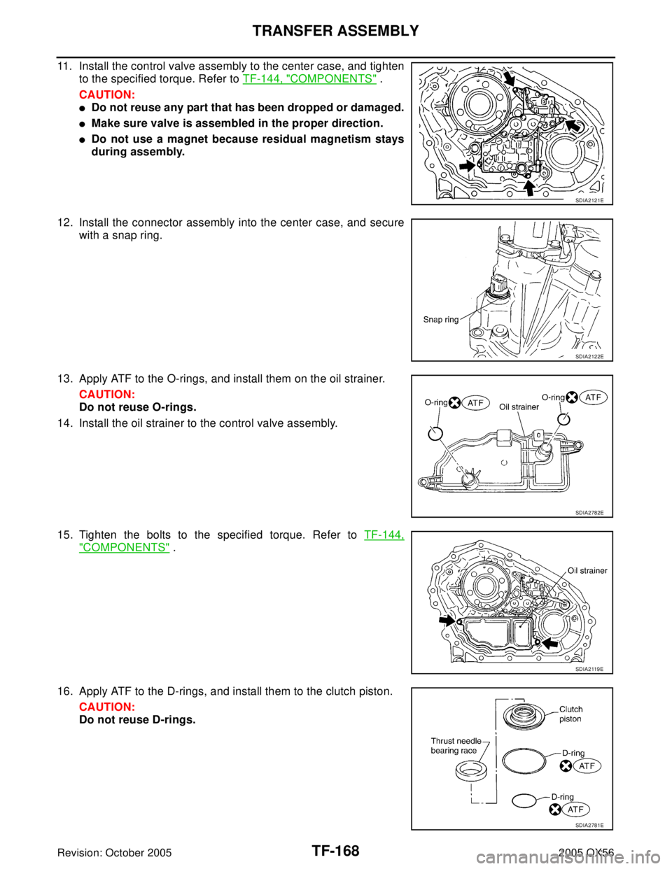
11. Install the control valve assembly to the center case, and tighten
to the specified torque. Refer to TF-144, "
COMPONENTS" .
CAUTION:
�Do not reuse any part that has been dropped or damaged.
�Make sure valve is assembled in the proper direction.
�Do not use a magnet because residual magnetism stays
during assembly.
12. Install the connector assembly into the center case, and secure
with a snap ring.
13. Apply ATF to the O-rings, and install them on the oil strainer.
CAUTION:
Do not reuse O-rings.
14. Install the oil strainer to the control valve assembly.
15. Tighten the bolts to the specified torque. Refer to TF-144,
"COMPONENTS" .
16. Apply ATF to the D-rings, and install them to the clutch piston.
CAUTION:
Do not reuse D-rings.
SDIA2121E
SDIA2122E
SDIA2782E
SDIA2 119 E
SDIA2781E
Page 3315 of 3419
TF-172
TRANSFER ASSEMBLY
Revision: October 20052005 QX56
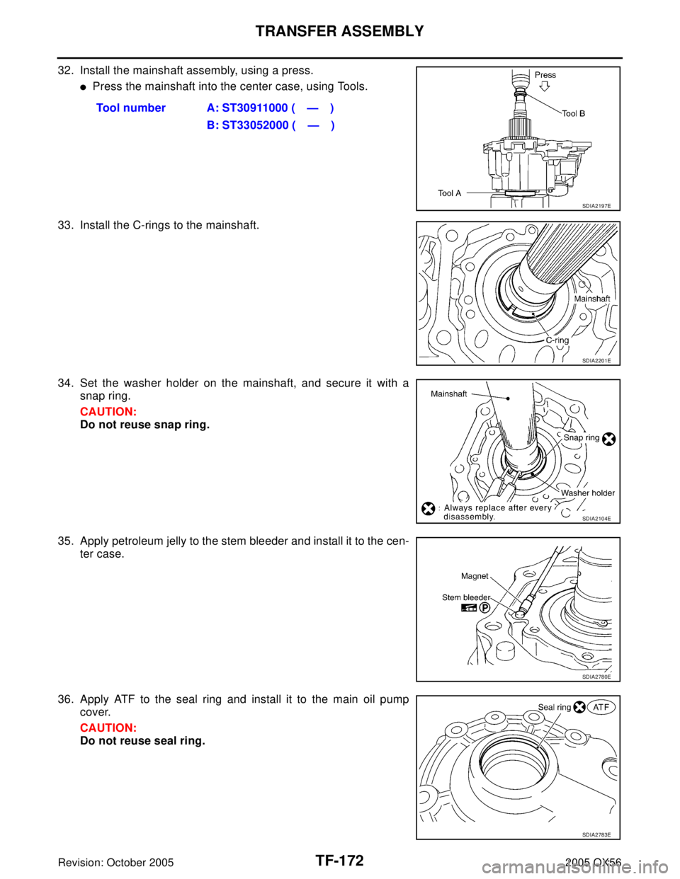
32. Install the mainshaft assembly, using a press.
�Press the mainshaft into the center case, using Tools.
33. Install the C-rings to the mainshaft.
34. Set the washer holder on the mainshaft, and secure it with a
snap ring.
CAUTION:
Do not reuse snap ring.
35. Apply petroleum jelly to the stem bleeder and install it to the cen-
ter case.
36. Apply ATF to the seal ring and install it to the main oil pump
cover.
CAUTION:
Do not reuse seal ring.Tool number A: ST30911000 ( — )
B: ST33052000 ( — )
SDIA2197E
SDIA2201E
SDIA2104E
SDIA2780E
SDIA2783E
Page 3319 of 3419
TF-176
TRANSFER ASSEMBLY
Revision: October 20052005 QX56
7. Set the mainshaft front bearing into the front case and install,
using Tool.
8. Install the snap ring into the front case.
CAUTION:
Do not reuse snap ring.
9. Install the internal gear with its groove facing the snap ring into
the front case. Then secure it with the snap ring.
CAUTION:
Do not reuse snap ring.
10. Install the oil seal until it is seated flush with the end face of the
front case, using Tool.
CAUTION:
�Do not reuse oil seal.
�Apply petroleum jelly to oil seal lip before installing.
11. Install the planetary carrier assembly and sun gear assembly to
the front case, using Tool.Tool number : ST30720000 (J-25405)
SDIA2172E
SDIA2171E
WDIA0100E
Tool number : KV38100500 ( — )
SDIA2785E
Tool number : ST33200000 (J-26082)
SDIA2183E
Page 3320 of 3419
TRANSFER ASSEMBLY
TF-177
C
E
F
G
H
I
J
K
L
MA
B
TF
Revision: October 20052005 QX56
12. Install the snap ring to the sun gear assembly.
CAUTION:
Do not reuse snap ring.
13. Apply petroleum jelly to the circumference of the oil seal, and
install it to the front case, using Tools.
CAUTION:
�Do not reuse oil seal.
�Apply petroleum jelly to oil seal.
14. Install the fork guide, shift fork spring, 2-4 fork, and L-H fork to
the shift rod, and secure them with retaining pins.
CAUTION:
Do not reuse retaining pins.
15. Install the 2-4 sleeve and L-H sleeve to each fork.
16. Install the shift cross to the front case.
17. While aligning the L-H sleeve with the planetary carrier, install
the shift rod assembly to the front case.
SDIA2144E
Dimension : 4.0 - 4.6 mm (0.157 - 0.181 mm)
Tool number A: ST30720000 (J-25405)
B: ST33200000 (J-26082)
SDIA2786E
SDIA2142E
SMT992C
SDIA2140E
Page 3342 of 3419
TROUBLE DIAGNOSES
WT-17
C
D
F
G
H
I
J
K
L
MA
B
WT
Revision: October 20052005 QX56
CONSULT-II Function (BCM)EES001Q2
CONSULT-II can display each diagnostic item using the diagnostic test modes shown following.
BCM
diagnostic test itemDiagnostic mode Description
Inspection by partWORK SUPPORTSupports inspections and adjustments. Commands are transmit-
ted to the BCM for setting the status suitable for required opera-
tion, input/output signals are received from the BCM and received
data is displayed.
DATA MONITOR Displays BCM input/output data in real time.
ACTIVE TESTOperation of electrical loads can be checked by sending drive sig-
nal to them.
SELF-DIAG RESULTS Displays BCM self-diagnosis results.
CAN DIAG SUPPORT MNTRThe result of transmit/receive diagnosis of CAN communication
can be read.
ECU PART NUMBER BCM part number can be read.
CONFIGURATION Performs BCM configuration read/write functions.
Page 3345 of 3419
WT-20
TROUBLE DIAGNOSES
Revision: October 20052005 QX56
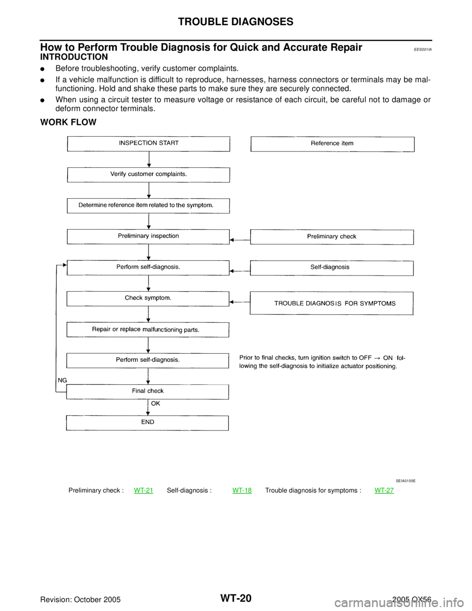
How to Perform Trouble Diagnosis for Quick and Accurate RepairEES001IA
INTRODUCTION
�Before troubleshooting, verify customer complaints.
�If a vehicle malfunction is difficult to reproduce, harnesses, harness connectors or terminals may be mal-
functioning. Hold and shake these parts to make sure they are securely connected.
�When using a circuit tester to measure voltage or resistance of each circuit, be careful not to damage or
deform connector terminals.
WORK FLOW
Preliminary check :WT-21Self-diagnosis :WT-18Trouble diagnosis for symptoms :WT-27
SEIA0100E
Page 3376 of 3419
EKS00BE1
CONSULT-II can display each diagnostic item using the diagnostic test mo")
FRONT WIPER AND WASHER SYSTEM
WW-17
C
D
E
F
G
H
I
J
L
MA
B
WW
Revision: October 20052005 QX56
CONSULT-II Function (BCM)EKS00BE1
CONSULT-II can display each diagnostic item using the diagnostic test modes shown following.
CONSULT-II OPERATION
CAUTION:
If CONSULT-II is used with no connection of CONSULT-II CONVERTER, malfunctions might be
detected in self-diagnosis depending on control unit which carries out CAN communication.
1. With the ignition switch OFF, connect CONSULT-II and CON-
SULT-II CONVERTER to the data link connector, then turn the
ignition switch ON.
2. Touch "START (NISSAN BASED VHCL)".
3. Touch "BCM" on the "SELECT SYSTEM" screen.
If "BCM" is not indicated, go to GI-39, "
CONSULT-II Data Link
Connector (DLC) Circuit" .
BCM diagnostic
test itemDiagnostic mode Description
Inspection by partWORK SUPPORTSupports inspections and adjustments. Commands are transmitted to the BCM
for setting the status suitable for required operation, input/output signals are
received from the BCM and received data is displayed.
DATA MONITOR Displays BCM input/output data in real time.
ACTIVE TEST Operation of electrical loads can be checked by sending drive signal to them.
SELF-DIAG RESULTS Displays BCM self-diagnosis results.
CAN DIAG SUPPORT MNTR The result of transmit/receive diagnosis of CAN communication can be read.
ECU PART NUMBER BCM part number can be read.
CONFIGURATION Performs BCM configuration read/write functions.
BBIA0369E
BCIA0029E
BCIA0030E
Page 3404 of 3419
EKS00BEH
CONSULT-II can display each diagnostic item using the diagnostic test mod")
REAR WIPER AND WASHER SYSTEM
WW-45
C
D
E
F
G
H
I
J
L
MA
B
WW
Revision: October 20052005 QX56
CONSULT-II Function (BCM)EKS00BEH
CONSULT-II can display each diagnostic item using the diagnostic test modes shown following.
CONSULT-II OPERATION
CAUTION:
If CONSULT-II is used with no connection of CONSULT-II CONVERTER, malfunctions might be
detected in self-diagnosis depending on control unit which carries out CAN communication.
1. With the ignition switch OFF, connect CONSULT-II and CON-
SULT-II CONVERTER to the data link connector, then turn the
ignition switch ON.
2. Touch "START (NISSAN BASED VHCL)".
3. Touch "BCM" on the "SELECT SYSTEM" screen.
If "BCM" is not indicated, go to GI-39, "
CONSULT-II Data Link
Connector (DLC) Circuit" .
BCM diagnostic
test itemDiagnostic mode Description
Inspection by partWORK SUPPORTSupports inspections and adjustments. Commands are transmitted to the BCM
for setting the status suitable for required operation, input/output signals are
received from the BCM and received data is displayed.
DATA MONITOR Displays BCM input/output data in real time.
ACTIVE TEST Operation of electrical loads can be checked by sending drive signal to them.
SELF-DIAG RESULTS Displays BCM self-diagnosis results.
CAN DIAG SUPPORT MNTR The result of transmit/receive diagnosis of CAN communication can be read.
ECU PART NUMBER BCM part number can be read.
CONFIGURATION Performs BCM configuration read/write functions.
BBIA0369E
BCIA0029E
BCIA0030E


EES001Q2
CONSULT-II can display each diagnostic item using the diagnostic test modes shown fo")