Page 2853 of 3419

RFD-6
FRONT OIL SEAL
Revision: October 20052005 QX56
FRONT OIL SEALPFP:38189
Removal and InstallationEDS003Q9
REMOVAL
1. Remove the drive shaft inside flange bolts to disconnect the rear drive shafts from the rear final drive.
Support the rear drive shafts using suitable wire.
NOTE:
Disconnecting the rear drive shafts is necessary to measure the total preload accurately.
2. Remove the rear propeller shaft. Refer to PR-9, "
REMOVAL" .
CAUTION:
Do not damage the propeller shaft tube.
3. Check the total preload. Refer to RFD-13, "
TOTAL PRELOAD" .
4. Put a mark on the end of the drive pinion corresponding to the
position mark “B” on the companion flange as shown.
CAUTION:
�Use paint to make the matching mark “B” on the drive
pinion. Never damage the drive pinion.
�The mark “B” on the companion flange indicates the
maximum vertical runout position.
5. Remove drive pinion nut using Tool as shown.
�Discard the drive pinion nut and use a new drive pinion nut for
installation.
6. Remove the companion flange using suitable tool as shown.
SDIA0270E
Tool number : KV40104000
LDIA0105E
LDIA0106E
Page 2854 of 3419

FRONT OIL SEAL
RFD-7
C
E
F
G
H
I
J
K
L
MA
B
RFD
Revision: October 20052005 QX56
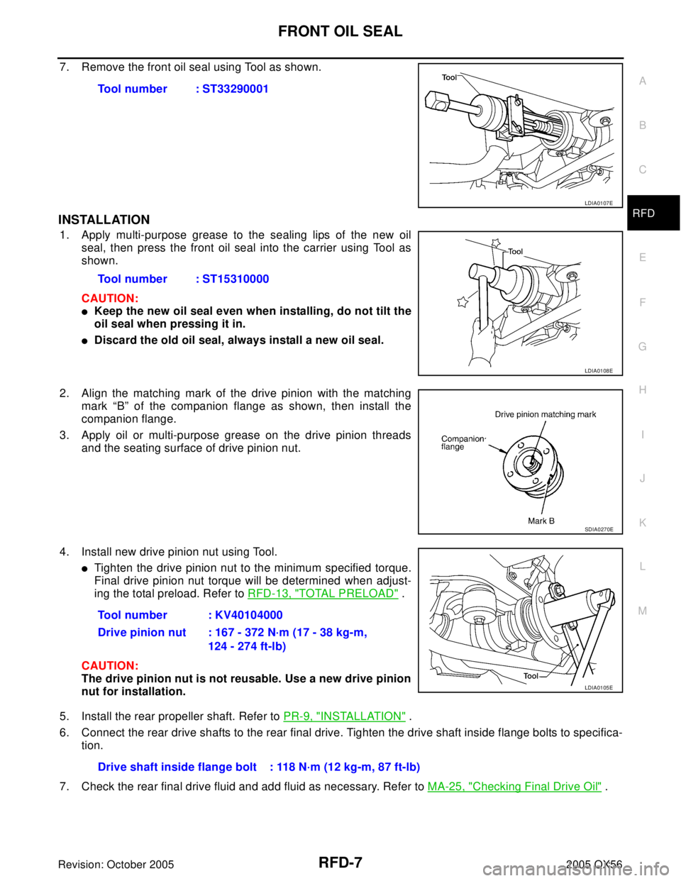
7. Remove the front oil seal using Tool as shown.
INSTALLATION
1. Apply multi-purpose grease to the sealing lips of the new oil
seal, then press the front oil seal into the carrier using Tool as
shown.
CAUTION:
�Keep the new oil seal even when installing, do not tilt the
oil seal when pressing it in.
�Discard the old oil seal, always install a new oil seal.
2. Align the matching mark of the drive pinion with the matching
mark “B” of the companion flange as shown, then install the
companion flange.
3. Apply oil or multi-purpose grease on the drive pinion threads
and the seating surface of drive pinion nut.
4. Install new drive pinion nut using Tool.
�Tighten the drive pinion nut to the minimum specified torque.
Final drive pinion nut torque will be determined when adjust-
ing the total preload. Refer to RFD-13, "
TOTAL PRELOAD" .
CAUTION:
The drive pinion nut is not reusable. Use a new drive pinion
nut for installation.
5. Install the rear propeller shaft. Refer to PR-9, "
INSTALLATION" .
6. Connect the rear drive shafts to the rear final drive. Tighten the drive shaft inside flange bolts to specifica-
tion.
7. Check the rear final drive fluid and add fluid as necessary. Refer to MA-25, "
Checking Final Drive Oil" . Tool number : ST33290001
LDIA0107E
Tool number : ST15310000
LDIA0108E
SDIA0270E
Tool number : KV40104000
Drive pinion nut : 167 - 372 N·m (17 - 38 kg-m,
124 - 274 ft-lb)
LDIA0105E
Drive shaft inside flange bolt : 118 N·m (12 kg-m, 87 ft-lb)
Page 2856 of 3419
SIDE OIL SEAL
RFD-9
C
E
F
G
H
I
J
K
L
MA
B
RFD
Revision: October 20052005 QX56
4. Check measurement “A” after the side flange installation is com-
plete as shown.
5. Connect the rear drive shafts to the rear final drive. Tighten the drive shaft inside flange bolts to specifica-
tion.Measurement “A” : approx. 339.5 mm (13.37 in)
SDIA1039E
Drive shaft inside flange bolts : 118 N·m (12 kg-m, 87 lb-ft)
Page 2858 of 3419
REAR FINAL DRIVE ASSEMBLY
RFD-11
C
E
F
G
H
I
J
K
L
MA
B
RFD
Revision: October 20052005 QX56
INSTALLATION
Installation is in the reverse order of removal.
CAUTION:
After installation, check the final drive oil level. Refer to MA-25, "
Checking Final Drive Oil" .
Page 2860 of 3419

REAR FINAL DRIVE ASSEMBLY
RFD-13
C
E
F
G
H
I
J
K
L
MA
B
RFD
Revision: October 20052005 QX56CAUTION:
Final drive pinion nut torque will be determined when adjusting the total preload. Refer to RFD-13,
"TOTAL PRELOAD" .
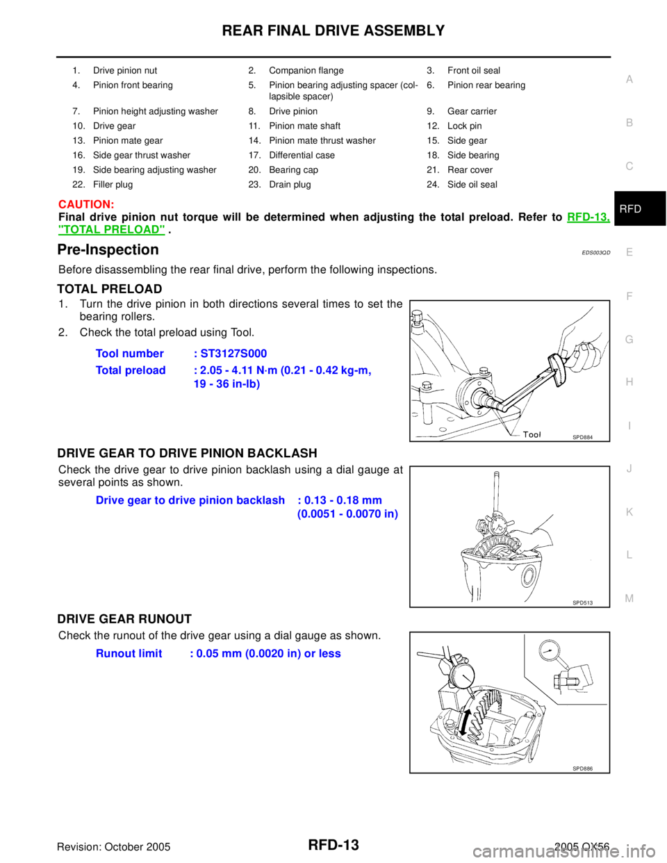
Pre-InspectionEDS003QD
Before disassembling the rear final drive, perform the following inspections.
TOTAL PRELOAD
1. Turn the drive pinion in both directions several times to set the
bearing rollers.
2. Check the total preload using Tool.
DRIVE GEAR TO DRIVE PINION BACKLASH
Check the drive gear to drive pinion backlash using a dial gauge at
several points as shown.
DRIVE GEAR RUNOUT
Check the runout of the drive gear using a dial gauge as shown.
1. Drive pinion nut 2. Companion flange 3. Front oil seal
4. Pinion front bearing 5. Pinion bearing adjusting spacer (col-
lapsible spacer)6. Pinion rear bearing
7. Pinion height adjusting washer 8. Drive pinion 9. Gear carrier
10. Drive gear 11. Pinion mate shaft 12. Lock pin
13. Pinion mate gear 14. Pinion mate thrust washer 15. Side gear
16. Side gear thrust washer 17. Differential case 18. Side bearing
19. Side bearing adjusting washer 20. Bearing cap 21. Rear cover
22. Filler plug 23. Drain plug 24. Side oil seal
Tool number : ST3127S000
Total preload : 2.05 - 4.11 N·m (0.21 - 0.42 kg-m,
19 - 36 in-lb)
SPD8 84
Drive gear to drive pinion backlash : 0.13 - 0.18 mm
(0.0051 - 0.0070 in)
SPD5 13
Runout limit : 0.05 mm (0.0020 in) or less
SPD8 86
Page 2865 of 3419
RFD-18
REAR FINAL DRIVE ASSEMBLY
Revision: October 20052005 QX56
4. Drive the pinion mate shaft lock pin out from the drive gear side
using a suitable punch.
INSPECTION
Contact Surfaces
1. Clean the disassembled parts in a suitable solvent and blow dry using compressed air.
2. If the following surfaces are burred or scratched, smooth them using an oil stone.
�Differential case
�Side gear
�Pinion mate gear
�Pinion mate shaft
Bearing
1. Thoroughly clean the bearing.
2. Check the bearing for wear, scratches, pitting, or flaking.
3. Check the tapered roller bearing for smooth rotation. If dam-
aged, replace the outer race and inner race as a set.
ADJUSTMENT OF DIFFERENTIAL CASE
Thrust Washer Selection
1. Install the side gears, pinion mate gears, and thrust washers into
the differential case.
SPD0 25
SPD7 15
SPD5 52
Page 2868 of 3419
REAR FINAL DRIVE ASSEMBLY
RFD-21
C
E
F
G
H
I
J
K
L
MA
B
RFD
Revision: October 20052005 QX56
1. Thoroughly clean the drive gear and drive pinion teeth.
2. Lightly apply a mixture of powdered ferric oxide and oil or the
equivalent. Apply it to 3 or 4 teeth of the drive gear drive side.
3. Use your hand to hold the companion flange steady and rotate
the drive gear in both directions.
4. Check the tooth contact as shown.
ASSEMBLY OF DIFFERENTIAL CASE ASSEMBLY
1. Install the pinion mate shaft lock pin using a suitable punch as
shown.
The lock pin must be flush with the case.
2. Place the differential case on the drive gear.
SPD3 57
SDIA0813E
SDIA1910E
SPD0 30
Page 2870 of 3419

REAR FINAL DRIVE ASSEMBLY
RFD-23
C
E
F
G
H
I
J
K
L
MA
B
RFD
Revision: October 20052005 QX56
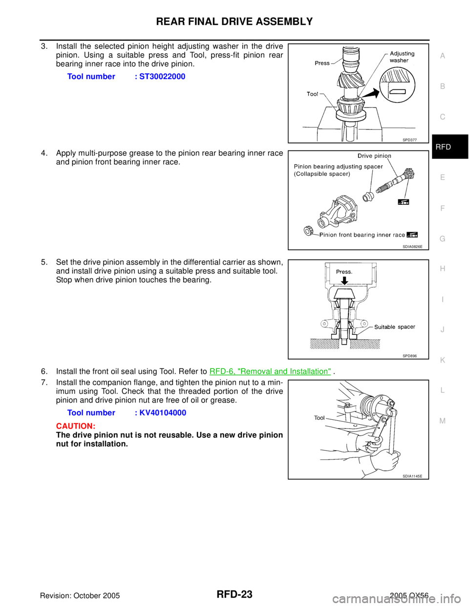
3. Install the selected pinion height adjusting washer in the drive
pinion. Using a suitable press and Tool, press-fit pinion rear
bearing inner race into the drive pinion.
4. Apply multi-purpose grease to the pinion rear bearing inner race
and pinion front bearing inner race.
5. Set the drive pinion assembly in the differential carrier as shown,
and install drive pinion using a suitable press and suitable tool.
Stop when drive pinion touches the bearing.
6. Install the front oil seal using Tool. Refer to RFD-6, "
Removal and Installation" .
7. Install the companion flange, and tighten the pinion nut to a min-
imum using Tool. Check that the threaded portion of the drive
pinion and drive pinion nut are free of oil or grease.
CAUTION:
The drive pinion nut is not reusable. Use a new drive pinion
nut for installation. Tool number : ST30022000
SPD3 77
SDIA0826E
SPD8 96
Tool number : KV40104000
SDIA11 45 E