Page 1638 of 3419
DTC P1217 ENGINE OVER TEMPERATURE
EC-447
C
D
E
F
G
H
I
J
K
L
MA
EC
Revision: October 20052005 QX56
8. CHECK MAIN 12 CAUSES
If the cause cannot be isolated, go to EC-448, "
Main 12 Causes of Overheating" .
>>INSPECTION END
PROCEDURE A
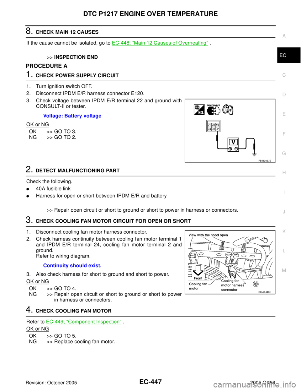
1. CHECK POWER SUPPLY CIRCUIT
1. Turn ignition switch OFF.
2. Disconnect IPDM E/R harness connector E120.
3. Check voltage between IPDM E/R terminal 22 and ground with
CONSULT-II or tester.
OK or NG
OK >> GO TO 3.
NG >> GO TO 2.
2. DETECT MALFUNCTIONING PART
Check the following.
�40A fusible link
�Harness for open or short between IPDM E/R and battery
>> Repair open circuit or short to ground or short to power in harness or connectors.
3. CHECK COOLING FAN MOTOR CIRCUIT FOR OPEN OR SHORT
1. Disconnect cooling fan motor harness connector.
2. Check harness continuity between cooling fan motor terminal 1
and IPDM E/R terminal 24, cooling fan motor terminal 2 and
ground.
Refer to wiring diagram.
3. Also check harness for short to ground and short to power.
OK or NG
OK >> GO TO 4.
NG >> Repair open circuit or short to ground or short to power
in harness or connectors.
4. CHECK COOLING FAN MOTOR
Refer to EC-449, "
Component Inspection" .
OK or NG
OK >> GO TO 5.
NG >> Replace cooling fan motor.Voltage: Battery voltage
PBIB2067E
Continuity should exist.
BBIA0446E
Page 1639 of 3419
EC-448Revision: October 2005
DTC P1217 ENGINE OVER TEMPERATURE
2005 QX56
5. CHECK INTERMITTENT INCIDENT
Perform EC-156, "
TROUBLE DIAGNOSIS FOR INTERMITTENT INCIDENT" .
OK or NG
OK >> Replace IPDM E/R. Refer to PG-17, "IPDM E/R (INTELLIGENT POWER DISTRIBUTION MOD-
ULE ENGINE ROOM)" .
NG >> Repair or replace harness connectors.
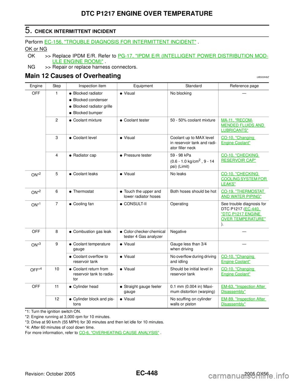
Main 12 Causes of OverheatingUBS00H8Z
*1: Turn the ignition switch ON.
*2: Engine running at 3,000 rpm for 10 minutes.
*3: Drive at 90 km/h (55 MPH) for 30 minutes and then let idle for 10 minutes.
*4: After 60 minutes of cool down time.
For more information, refer to CO-6, "
OVERHEATING CAUSE ANALYSIS" . Engine Step Inspection item Equipment Standard Reference page
OFF 1
�Blocked radiator
�Blocked condenser
�Blocked radiator grille
�Blocked bumper
�Visual No blocking —
2
�Coolant mixture�Coolant tester 50 - 50% coolant mixtureMA-11, "RECOM-
MENDED FLUIDS AND
LUBRICANTS"
3�Coolant level�Visual Coolant up to MAX level
in reservoir tank and radi-
ator filler neckCO-10, "Changing
Engine Coolant"
4�Radiator cap�Pressure tester 59 - 98 kPa
(0.6 - 1.0 kg/cm2 , 9 - 14
psi) (Limit)CO-10, "
CHECKING
RESERVOIR CAP"
ON*25�Coolant leaks�Visual No leaksCO-10, "CHECKING
COOLING SYSTEM FOR
LEAKS"
ON*26�Thermostat�Touch the upper and
lower radiator hosesBoth hoses should be hotCO-19, "THERMOSTAT
AND WATER PIPING"
ON*17�Cooling fan�CONSULT-II Operating See trouble diagnosis for
DTC P1217 (EC-440,
"DTC P1217 ENGINE
OVER TEMPERATURE"
).
OFF 8
�Combustion gas leak�Color checker chemical
tester 4 Gas analyzerNegative —
ON*
39�Coolant temperature
gauge�Visual Gauge less than 3/4
when driving—
�Coolant overflow to
reservoir tank�Visual No overflow during driving
and idlingCO-10, "Changing
Engine Coolant"
OFF*410�Coolant return from
reservoir tank to radia-
tor�Visual Should be initial level in
reservoir tankCO-10, "Changing
Engine Coolant"
OFF 11�Cylinder head�Straight gauge feeler
gauge0.1 mm (0.004 in) Maxi-
mum distortion (warping)EM-63, "Inspection After
Disassembly"
12�Cylinder block and pis-
tons�Visual No scuffing on cylinder
walls or pistonEM-89, "Inspection After
Disassembly"
Page 1640 of 3419
DTC P1217 ENGINE OVER TEMPERATURE
EC-449
C
D
E
F
G
H
I
J
K
L
MA
EC
Revision: October 20052005 QX56
Component InspectionUBS00H90
COOLING FAN MOTOR
1. Disconnect cooling fan motor harness connector.
2. Supply cooling fan motor terminals with battery voltage and
check operation.
Cooling fan motor should operate.
If NG, replace cooling fan motor.
SEF 8 88 V
Page 1834 of 3419
REFRIGERANT PRESSURE SENSOR
EC-643
C
D
E
F
G
H
I
J
K
L
MA
EC
Revision: October 20052005 QX56
REFRIGERANT PRESSURE SENSORPFP:92136
Component DescriptionUBS00HDH
The refrigerant pressure sensor is installed at the liquid tank of the
air conditioner system. The sensor uses an electrostatic volume
pressure transducer to convert refrigerant pressure to voltage. The
voltage signal is sent to ECM, and ECM controls cooling fan system.
BBIA0445E
SEF 0 99 XA
Page 1915 of 3419
EM-12Revision: October 2005
DRIVE BELTS
2005 QX56
DRIVE BELTSPFP:02117
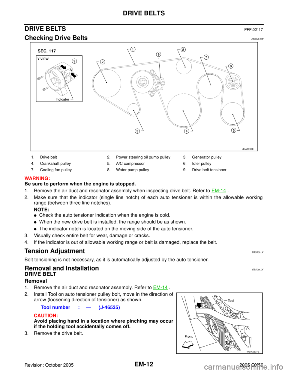
Checking Drive BeltsEBS00LLW
WAR NIN G:
Be sure to perform when the engine is stopped.
1. Remove the air duct and resonator assembly when inspecting drive belt. Refer to EM-14
.
2. Make sure that the indicator (single line notch) of each auto tensioner is within the allowable working
range (between three line notches).
NOTE:
�Check the auto tensioner indication when the engine is cold.
�When the new drive belt is installed, the range should be as shown.
�The indicator notch is located on the moving side of the auto tensioner.
3. Visually check entire belt for wear, damage or cracks.
4. If the indicator is out of allowable working range or belt is damaged, replace the belt.
Tension AdjustmentEBS00LLX
Belt tensioning is not necessary, as it is automatically adjusted by the auto tensioner.
Removal and InstallationEBS00LLY
DRIVE BELT
Removal
1. Remove the air duct and resonator assembly. Refer to EM-14 .
2. Install Tool on auto tensioner pulley bolt, move in the direction of
arrow (loosening direction of tensioner) as shown.
CAUTION:
Avoid placing hand in a location where pinching may occur
if the holding tool accidentally comes off.
3. Remove the drive belt.
LBIA0391E
1. Drive belt 2. Power steering oil pump pulley 3. Generator pulley
4. Crankshaft pulley 5. A/C compressor 6. Idler pulley
7. Cooling fan pulley 8. Water pump pulley 9. Drive belt tensioner
Tool number : — (J-46535)
WBIA0537E
Page 1922 of 3419
EXHAUST MANIFOLD AND THREE WAY CATALYST
EM-19
C
D
E
F
G
H
I
J
K
L
MA
EM
Revision: October 20052005 QX56
EXHAUST MANIFOLD AND THREE WAY CATALYSTPFP:14004
Removal and InstallationEBS00LM2
REMOVAL
WA RN ING:
Perform the work when the exhaust and cooling system have cooled sufficiently.
1. Remove the air duct and resonator assembly. Refer to EM-14, "
REMOVAL" .
2. Drain the engine coolant from the radiator. Refer to MA-13, "
DRAINING ENGINE COOLANT" .
3. Remove the engine undercover using power tool.
4. Remove the radiator and radiator hoses. Refer to CO-12, "
RADIATOR" .
5. Remove the drive belts. Refer to EM-12, "
Removal" .
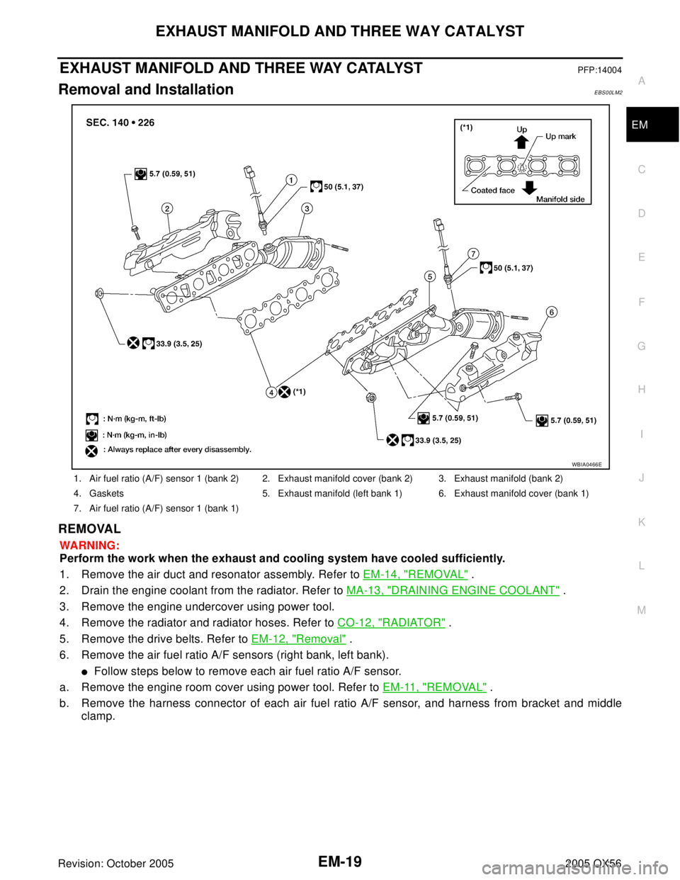
6. Remove the air fuel ratio A/F sensors (right bank, left bank).
�Follow steps below to remove each air fuel ratio A/F sensor.
a. Remove the engine room cover using power tool. Refer to EM-11, "
REMOVAL" .
b. Remove the harness connector of each air fuel ratio A/F sensor, and harness from bracket and middle
clamp.
1. Air fuel ratio (A/F) sensor 1 (bank 2) 2. Exhaust manifold cover (bank 2) 3. Exhaust manifold (bank 2)
4. Gaskets 5. Exhaust manifold (left bank 1) 6. Exhaust manifold cover (bank 1)
7. Air fuel ratio (A/F) sensor 1 (bank 1)
WBIA0466E
Page 1959 of 3419
EM-56Revision: October 2005
OIL SEAL
2005 QX56
Removal and Installation of Front Oil SealEBS00LMC
REMOVAL
1. Remove the radiator. Refer to CO-12, "Removal and Installation" .
2. Remove cooling fan. Refer to CO-15, "
Removal and Installation (Crankshaft Driven Type)" .
3. Remove the crankshaft pulley. Refer to EM-35, "
TIMING CHAIN" .
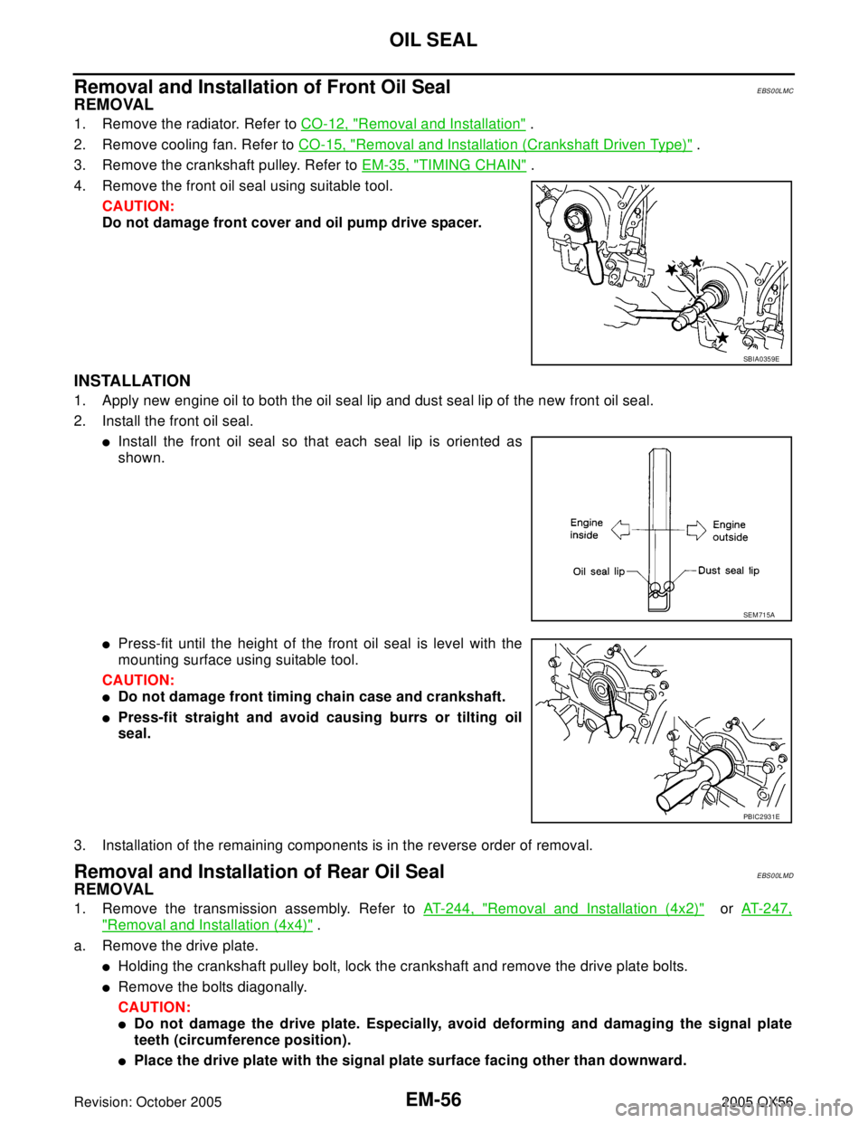
4. Remove the front oil seal using suitable tool.
CAUTION:
Do not damage front cover and oil pump drive spacer.
INSTALLATION
1. Apply new engine oil to both the oil seal lip and dust seal lip of the new front oil seal.
2. Install the front oil seal.
�Install the front oil seal so that each seal lip is oriented as
shown.
�Press-fit until the height of the front oil seal is level with the
mounting surface using suitable tool.
CAUTION:
�Do not damage front timing chain case and crankshaft.
�Press-fit straight and avoid causing burrs or tilting oil
seal.
3. Installation of the remaining components is in the reverse order of removal.
Removal and Installation of Rear Oil SealEBS00LMD
REMOVAL
1. Remove the transmission assembly. Refer to AT-244, "Removal and Installation (4x2)" or AT-247,
"Removal and Installation (4x4)" .
a. Remove the drive plate.
�Holding the crankshaft pulley bolt, lock the crankshaft and remove the drive plate bolts.
�Remove the bolts diagonally.
CAUTION:
�Do not damage the drive plate. Especially, avoid deforming and damaging the signal plate
teeth (circumference position).
�Place the drive plate with the signal plate surface facing other than downward.
SBIA0359E
SEM 71 5A
PBIC2931E
Page 1975 of 3419
EM-72Revision: October 2005
ENGINE ASSEMBLY
2005 QX56
INSTALLATION
Installation is in the reverse order of removal.
CAUTION:
�When replacing an engine or transmission you must make sure the dowels are installed correctly
during re-assembly.
�Improper alignment caused by missing dowels may cause vibration, oil leaks or breakage of driv-
etrain components.
INSPECTION AFTER INSTALLATION
�Before starting the engine, check oil/fluid levels including engine coolant and engine oil. If the levels are
lower than required quantity, fill to the specified level. Refer to MA-11, "
RECOMMENDED FLUIDS AND
LUBRICANTS" .
�Use procedure below to check for fuel leakage.
�Turn ignition switch ON (with engine stopped). With fuel pressure applied to the fuel piping, check for fuel
leakage at the connection points.
�Start engine. With engine speed increased, check again for fuel leakage at connection points.
�Run engine to check for unusual noise and vibration.
�Warm up engine thoroughly to make sure there is no leakage of fuel, exhaust gas, or any oils/fluids includ-
ing engine oil and engine coolant.
�Bleed air from passages in lines and hoses, such as in cooling system.
�After cooling down the engine, again check oil/fluid levels including engine oil and engine coolant. Refill to
specified level if necessary.
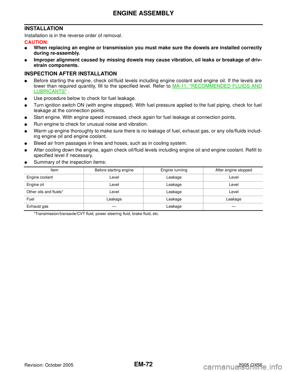
�Summary of the inspection items:
*Transmission/transaxle/CVT fluid, power steering fluid, brake fluid, etc.Item Before starting engine Engine running After engine stopped
Engine coolant Level Leakage Level
Engine oil Level Leakage Level
Other oils and fluids* Level Leakage Level
Fuel Leakage Leakage Leakage
Exhaust gas — Leakage —