2005 INFINITI FX35 display
[x] Cancel search: displayPage 4545 of 4731
SE-72
AUTOMATIC DRIVE POSITIONER
Revision: 2005 July 2005 FX
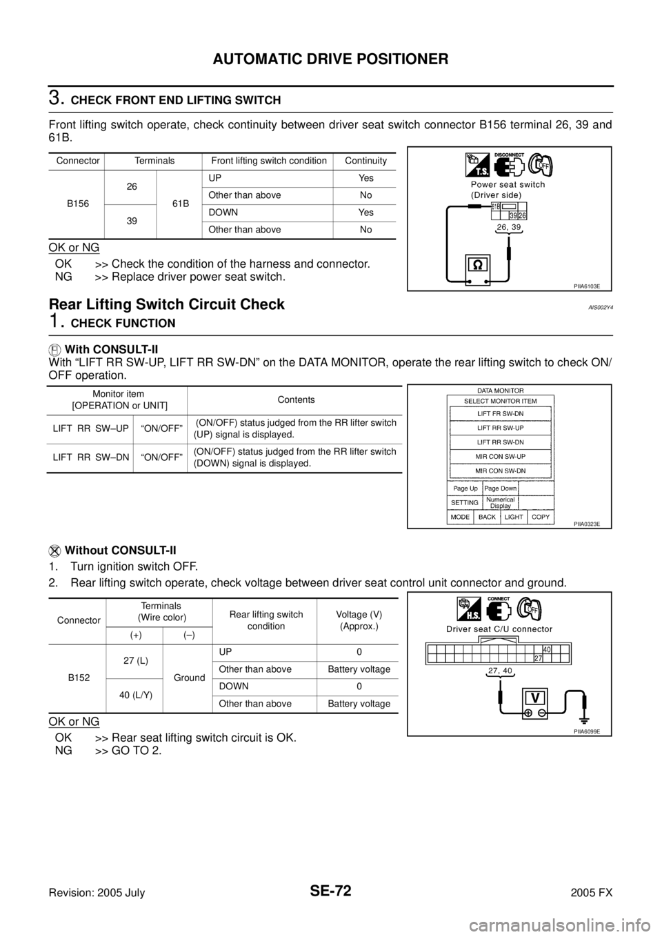
3. CHECK FRONT END LIFTING SWITCH
Front lifting switch operate, check continuity between driver seat switch connector B156 terminal 26, 39 and
61B.
OK or NG
OK >> Check the condition of the harness and connector.
NG >> Replace driver power seat switch.
Rear Lifting Switch Circuit CheckAIS002Y4
1. CHECK FUNCTION
With CONSULT-II
With “LIFT RR SW-UP, LIFT RR SW-DN” on the DATA MONITOR, operate the rear lifting switch to check ON/
OFF operation.
Without CONSULT-II
1. Turn ignition switch OFF.
2. Rear lifting switch operate, check voltage between driver seat control unit connector and ground.
OK or NG
OK >> Rear seat lifting switch circuit is OK.
NG >> GO TO 2.
Connector Terminals Front lifting switch condition Continuity
B156 26
61B UP Yes
Other than above No
39 DOWN Yes
Other than above No
PIIA6103E
Monitor item
[OPERATION or UNIT] Contents
LIFT RR SW–UP “ON/OFF” (ON/OFF) status judged from the RR lifter switch
(UP) signal is displayed.
LIFT RR SW–DN “ON/OFF” (ON/OFF) status judged from the RR lifter switch
(DOWN) signal is displayed.
PIIA0323E
Connector Terminals
(Wire color) Rear lifting switch
condition Voltage (V)
(Approx.)
(+) (–)
B152 27 (L)
Ground UP 0
Other than above Battery voltage
40 (L/Y) DOWN 0
Other than above Battery voltage
PIIA6099E
Page 4547 of 4731
SE-74
AUTOMATIC DRIVE POSITIONER
Revision: 2005 July 2005 FX
Front Lifting Switch and Rear Lifting Switch Ground Circuit CheckAIS003L3
1. CHECK POWER SEAT SWITCH GROUND CIRCUIT
1. Turn ignition switch OFF.
2. Disconnect power seat switch connector.
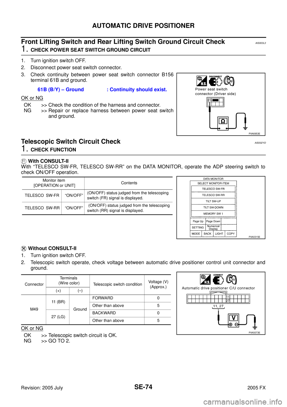
3. Check continuity between power seat switch connector B156 terminal 61B and ground.
OK or NG
OK >> Check the condition of the harness and connector.
NG >> Repair or replace harness between power seat switch and ground.
Telescopic Switch Circuit CheckAIS002YD
1. CHECK FUNCTION
With CONSULT-II
With “TELESCO SW-FR, TELESCO SW-RR” on the DATA MONITOR, operate the ADP steering switch to
check ON/OFF operation.
Without CONSULT-II
1. Turn ignition switch OFF.
2. Telescopic switch operate, check voltage between automatic drive positioner control unit connector and ground.
OK or NG
OK >> Telescopic switch circuit is OK.
NG >> GO TO 2. 61B (B/Y) – Ground : Continuity should exist.
PIIA6953E
Monitor item
[OPERATION or UNIT] Contents
TELESCO SW-FR “ON/OFF” (ON/OFF) status judged from the telescoping
switch (FR) signal is displayed.
TELESCO SW-RR “ON/OFF” (ON/OFF) status judged from the telescoping
switch (RR) signal is displayed.
PIIA0315E
Connector Terminals
(Wire color) Telescopic switch condition Voltage (V)
(Approx.)
(+) (–)
M49 11 ( B R )
Ground FORWARD 0
Other than above 5
27 (LG) BACKWARD 0
Other than above 5
PIIA5073E
Page 4549 of 4731
SE-76
AUTOMATIC DRIVE POSITIONER
Revision: 2005 July 2005 FX
Tilt Switch Circuit CheckAIS002YE
1. CHECK FUNCTION
With CONSULT-II
With “TILT SW-UP,TILT SW-DOWN” on the DATA MONITOR, operate the ADP steering switch to check ON/
OFF operation.
Without CONSULT-II
1. Turn ignition switch OFF.
2. Tilt switch operate, check voltage between automatic drive positioner control unit connector and ground.
OK or NG
OK >> Tilt switch circuit is OK.
NG >> GO TO 2.
2. CHECK TILT SWITCH CIRCUIT HARNESS CONTINUITY
1. Disconnect automatic drive positioner control unit connector and ADP steering switch connector.
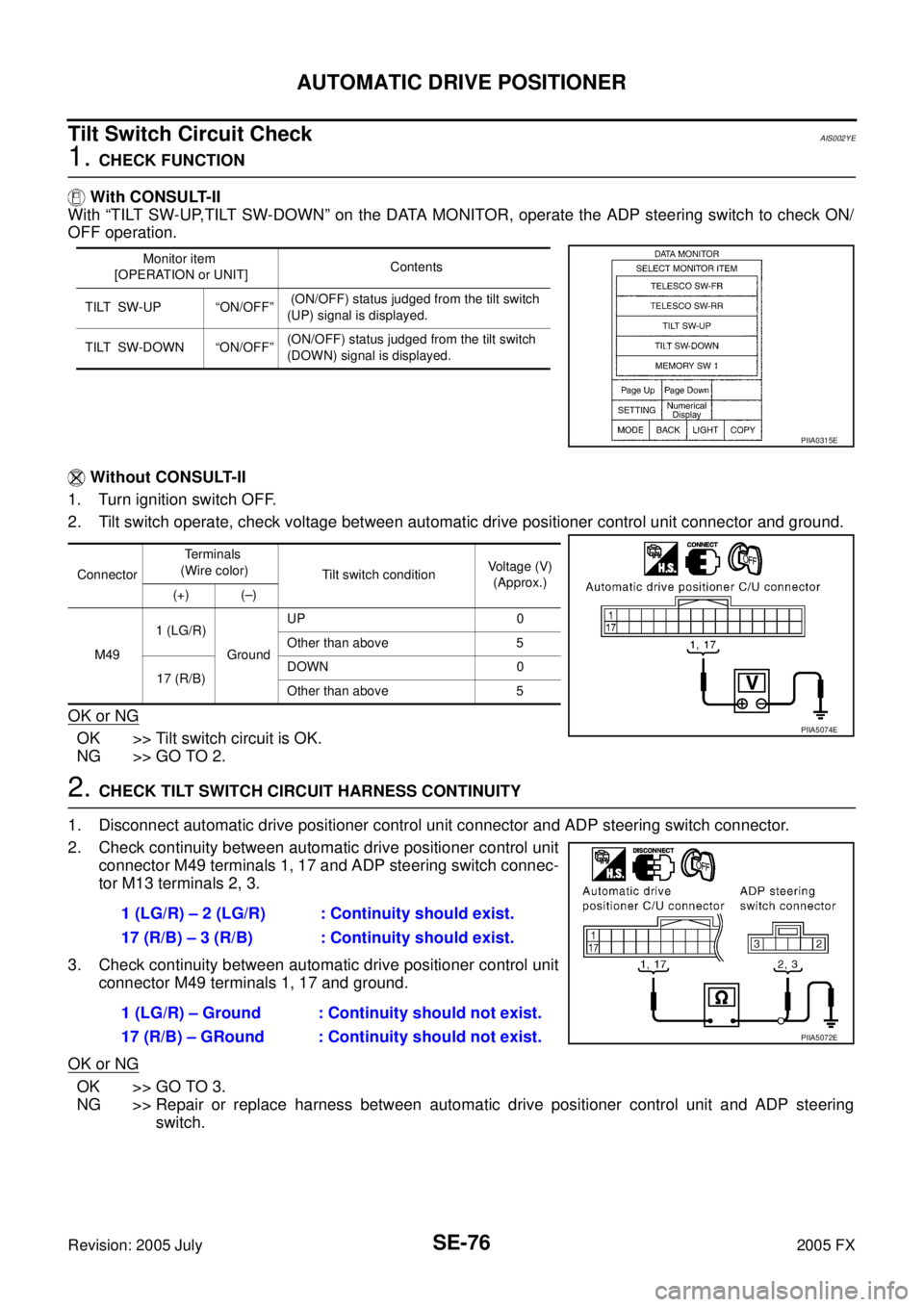
2. Check continuity between automatic drive positioner control unit connector M49 terminals 1, 17 and ADP steering switch connec-
tor M13 terminals 2, 3.
3. Check continuity between automatic drive positioner control unit connector M49 terminals 1, 17 and ground.
OK or NG
OK >> GO TO 3.
NG >> Repair or replace harness between automatic drive positioner control unit and ADP steering
switch.
Monitor item
[OPERATION or UNIT] Contents
TILT SW-UP “ON/OFF” (ON/OFF) status judged from the tilt switch
(UP) signal is displayed.
TILT SW-DOWN “ON/OFF” (ON/OFF) status judged from the tilt switch
(DOWN) signal is displayed.
PIIA0315E
Connector Te r m i n a l s
(Wire color) Tilt switch condition Voltage (V)
(Approx.)
(+) (–)
M49 1 (LG/R)
Ground UP 0
Other than above 5
17 (R/B) DOWN 0
Other than above 5
PIIA5074E
1 (LG/R) – 2 (LG/R) : Continuity should exist.
17 (R/B) – 3 (R/B) : Continuity should exist.
1 (LG/R) – Ground : Continuity should not exist.
17 (R/B) – GRound : Continuity should not exist.
PIIA5072E
Page 4551 of 4731
SE-78
AUTOMATIC DRIVE POSITIONER
Revision: 2005 July 2005 FX
Door Mirror Remote Control Switch (Changeover Switch) Circuit CheckAIS003BY
1. CHECK FUNCTION
With CONSULT-II
Check the operation on “MIR CHNG SW-R” or “MIR CHNG SW-L” in the DATA MONITOR.
Without CONSULT-II
1. Turn ignition switch ACC.
2. Change over switch operate, check voltage between automatic drive positioner control unit connector and ground.
OK
orNG
OK >> Door mirror remote control switch (changeover switch) circuit is OK.
NG >> GO TO 2.
2. CHECK CHANGEOVER SWITCH CIRCUIT HARNESS CONTINUITY
1. Turn ignition switch OFF.
2. Disconnect automatic drive positioner control unit and door mirror remote control unit connector.
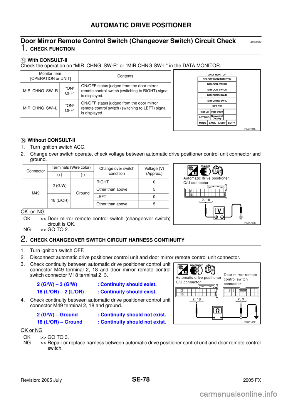
3. Check continuity between automatic drive positioner control unit connector M49 terminal 2, 18 and door mirror remote control
switch connector M18 terminal 2, 3.
4. Check continuity between automatic drive positioner control unit connector M49 terminal 2, 18 and ground.
OK or NG
OK >> GO TO 3.
NG >> Repair or replace harness between automatic drive positioner control unit and door remote control switch.
Monitor item
[OPERATION or UNIT] Contents
MIR CHNG SW–R “ON/
OFF” ON/OFF status judged from the door mirror
remote control switch (switching to RIGHT) signal
is displayed.
MIR CHNG SW–L “ON/
OFF” ON/OFF status judged from the door mirror
remote control switch (switching to LEFT) signal
is displayed.
PIIA0191E
Connector Terminals (Wire color)
Change over switch
condition Voltage (V)
(Approx.)
(+) (-)
M49 2 (G/W)
Ground RIGHT 0
Other than above 5
18 (L/OR) LEFT 0
Other than above 5
PIIA4767E
2 (G/W) – 3 (G/W) : Continuity should exist.
18 (L/OR) – 2 (L/OR) : Continuity should exist.
2 (G/W) – Ground : Continuity should not exist.
18 (L/OR) – Ground : Continuity should not exist.
PIIB3165E
Page 4553 of 4731
SE-80
AUTOMATIC DRIVE POSITIONER
Revision: 2005 July 2005 FX
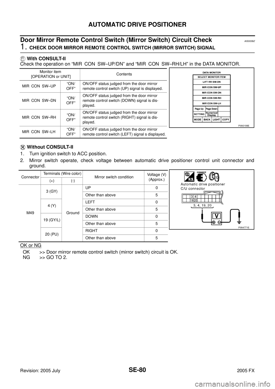
Door Mirror Remote Control Switch (Mirror Switch) Circuit CheckAIS003BZ
1. CHECK DOOR MIRROR REMOTE CONTROL SWITCH (MIRROR SWITCH) SIGNAL
With CONSULT-II
Check the operation on “MIR CON SW–UP/DN” and “MIR CON SW–RH/LH” in the DATA MONITOR.
Without CONSULT-II
1. Turn ignition switch to ACC position.
2. Mirror switch operate, check voltage between automatic drive positioner control unit connector and ground.
OK or NG
OK >> Door mirror remote control switch (mirror switch) circuit is OK.
NG >> GO TO 2.
Monitor item
[OPERATION or UNIT] Contents
MIR CON SW–UP “ON/
OFF” ON/OFF status judged from the door mirror
remote control switch (UP) signal is displayed.
MIR CON SW–DN “ON/
OFF” ON/OFF status judged from the door mirror
remote control switch (DOWN) signal is dis-
played.
MIR CON SW–RH “ON/
OFF” ON/OFF status judged from the door mirror
remote control switch (RIGHT) signal is dis-
played.
MIR CON SW–LH “ON/
OFF” ON/OFF status judged from the door mirror
remote control switch (LEFT) signal s displayed.
PIIA0199E
Connector Terminals (Wire color)
Mirror switch condition Voltage (V)
(Approx.)
(+) (-)
M49 3 (GY)
Ground UP 0
Other than above 5
4 (Y) LEFT 0
Other than above 5
19 (GY/L) DOWN 0
Other than above 5
20 (PU) RIGHT 0
Other than above 5
PIIA4771E
Page 4555 of 4731
SE-82
AUTOMATIC DRIVE POSITIONER
Revision: 2005 July 2005 FX
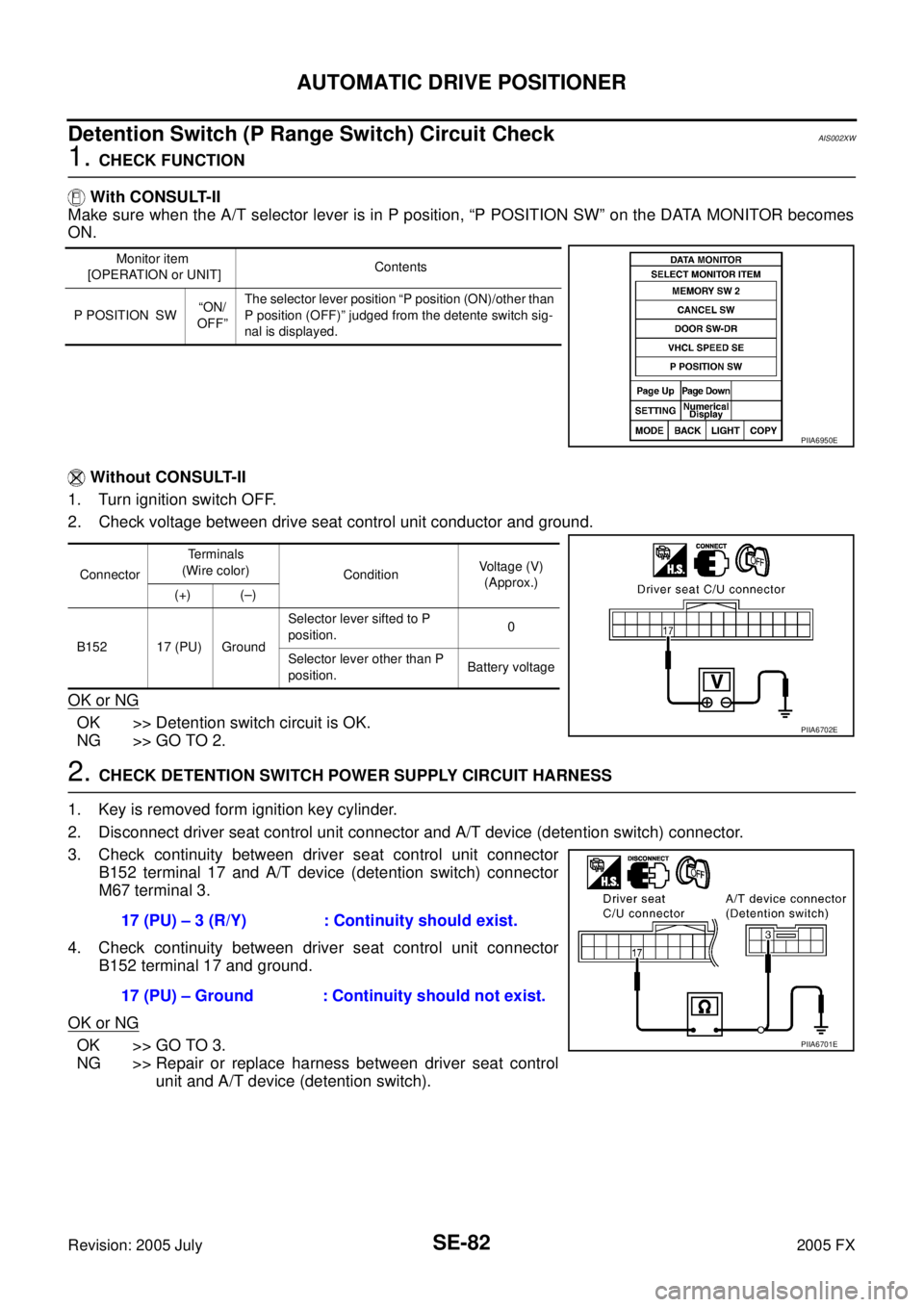
Detention Switch (P Range Switch) Circuit CheckAIS002XW
1. CHECK FUNCTION
With CONSULT-II
Make sure when the A/T selector lever is in P position, “P POSITION SW” on the DATA MONITOR becomes
ON.
Without CONSULT-II
1. Turn ignition switch OFF.
2. Check voltage between drive seat control unit conductor and ground.
OK or NG
OK >> Detention switch circuit is OK.
NG >> GO TO 2.
2. CHECK DETENTION SWITCH POWER SUPPLY CIRCUIT HARNESS
1. Key is removed form ignition key cylinder.
2. Disconnect driver seat control unit connector and A/T device (detention switch) connector.
3. Check continuity between driver seat control unit connector B152 terminal 17 and A/T device (detention switch) connector
M67 terminal 3.
4. Check continuity between driver seat control unit connector B152 terminal 17 and ground.
OK or NG
OK >> GO TO 3.
NG >> Repair or replace harness between driver seat control unit and A/T device (detention switch).
Monitor item
[OPERATION or UNIT] Contents
P POSITION SW “ON/
OFF” The selector lever position “P position (ON)/other than
P position (OFF)” judged from the detente switch sig-
nal is displayed.
PIIA6950E
Connector Terminals
(Wire color) Condition Voltage (V)
(Approx.)
(+) (–)
B152 17 (PU) Ground Selector lever sifted to P
position. 0
Selector lever other than P
position. Battery voltage
PIIA6702E
17 (PU) – 3 (R/Y) : Continuity should exist.
17 (PU) – Ground : Continuity should not exist.
PIIA6701E
Page 4556 of 4731
AUTOMATIC DRIVE POSITIONER SE-83
C
D E
F
G H
J
K L
M A
B
SE
Revision: 2005 July 2005 FX
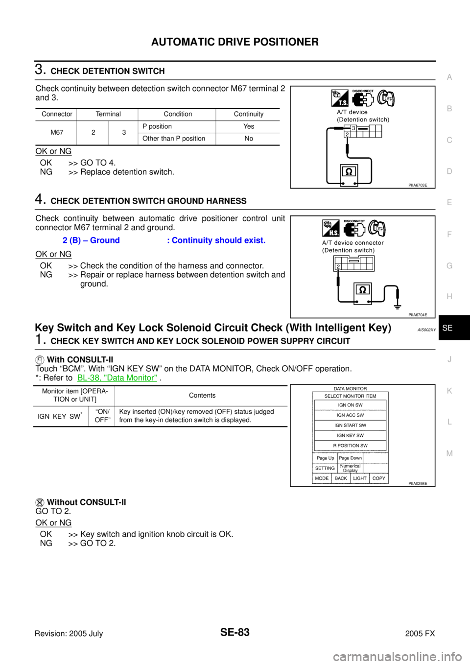
3. CHECK DETENTION SWITCH
Check continuity between detection switch connector M67 terminal 2
and 3.
OK or NG
OK >> GO TO 4.
NG >> Replace detention switch.
4. CHECK DETENTION SWITCH GROUND HARNESS
Check continuity between automatic drive positioner control unit
connector M67 terminal 2 and ground.
OK or NG
OK >> Check the condition of the harness and connector.
NG >> Repair or replace harness between detention switch and
ground.
Key Switch and Key Lock Solenoid Circuit Check (With Intelligent Key)AIS002XY
1. CHECK KEY SWITCH AND KEY LOCK SOLENOID POWER SUPPRY CIRCUIT
With CONSULT-II
Touch “BCM”. With “IGN KEY SW” on the DATA MONITOR, Check ON/OFF operation.
*: Refer to BL-38, "
Data Monitor" .
Without CONSULT-II
GO TO 2.
OK or NG
OK >> Key switch and ignition knob circuit is OK.
NG >> GO TO 2.
Connector Terminal Condition Continuity
M67 2 3 P position Yes
Other than P position No
PIIA6703E
2 (B) – Ground : Continuity should exist.
PIIA6704E
Monitor item [OPERA- TION or UNIT] Contents
IGN KEY SW
*“ON/
OFF” Key inserted (ON)/key removed (OFF) status judged
from the key-in detection switch is displayed.
PIIA0298E
Page 4558 of 4731
AUTOMATIC DRIVE POSITIONER SE-85
C
D E
F
G H
J
K L
M A
B
SE
Revision: 2005 July 2005 FX
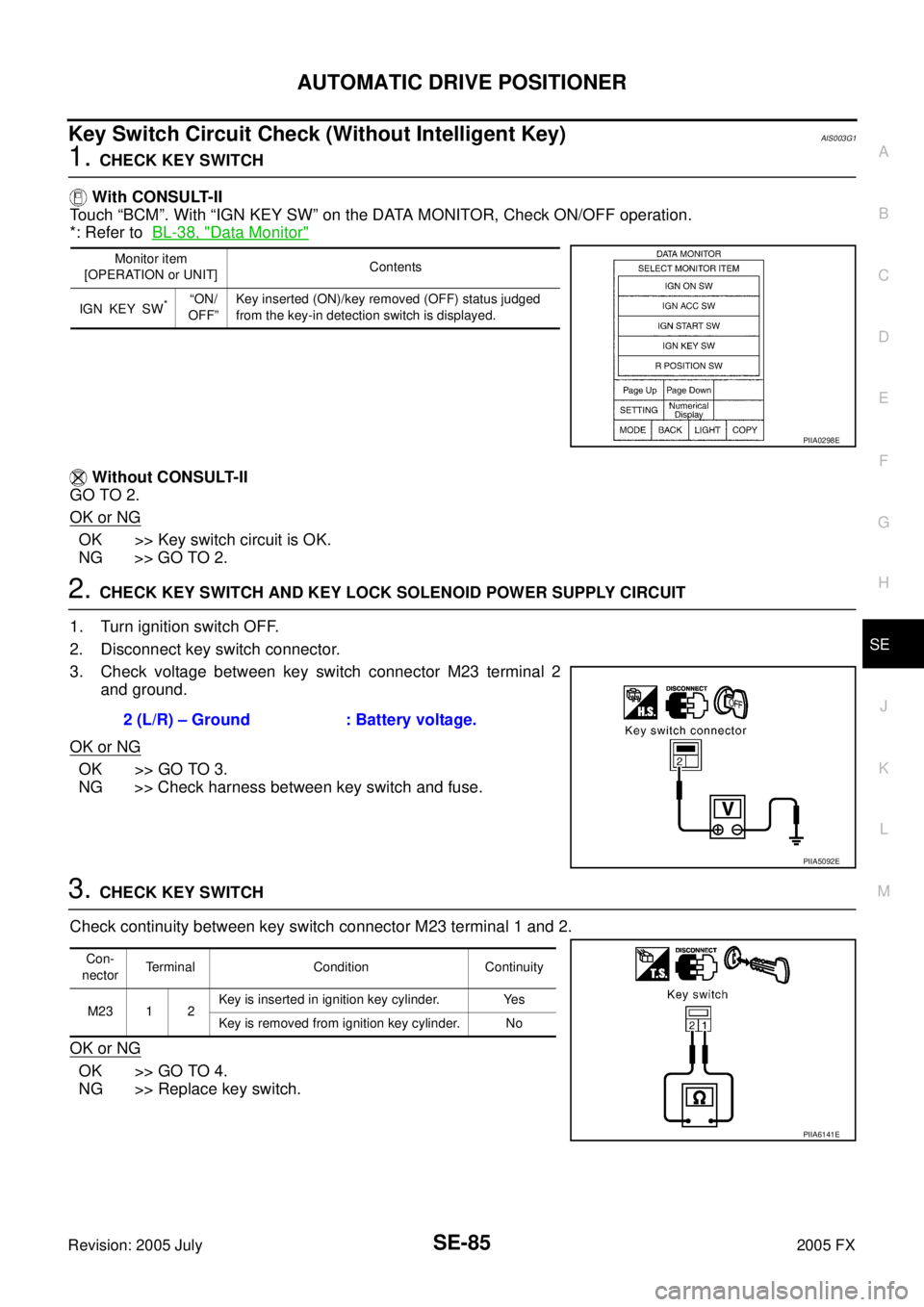
Key Switch Circuit Check (Without Intelligent Key)AIS003G1
1. CHECK KEY SWITCH
With CONSULT-II
Touch “BCM”. With “IGN KEY SW” on the DATA MONITOR, Check ON/OFF operation.
*: Refer to BL-38, "
Data Monitor"
Without CONSULT-II
GO TO 2.
OK or NG
OK >> Key switch circuit is OK.
NG >> GO TO 2.
2. CHECK KEY SWITCH AND KEY LOCK SOLENOID POWER SUPPLY CIRCUIT
1. Turn ignition switch OFF.
2. Disconnect key switch connector.
3. Check voltage between key switch connector M23 terminal 2 and ground.
OK or NG
OK >> GO TO 3.
NG >> Check harness between key switch and fuse.
3. CHECK KEY SWITCH
Check continuity between key switch connector M23 terminal 1 and 2.
OK or NG
OK >> GO TO 4.
NG >> Replace key switch.
Monitor item
[OPERATION or UNIT] Contents
IGN KEY SW
*“ON/
OFF” Key inserted (ON)/key removed (OFF) status judged
from the key-in detection switch is displayed.
PIIA0298E
2 (L/R) – Ground : Battery voltage.
PIIA5092E
Con-
nector Terminal Condition Continuity
M23 1 2 Key is inserted in ignition key cylinder. Yes
Key is removed from ignition key cylinder. No
PIIA6141E