2005 INFINITI FX35 Compartment filter
[x] Cancel search: Compartment filterPage 440 of 4731

ATC-3
C
D E
F
G H
I
K L
M A
B
AT C
Revision: 2005 July 2005 FX
COMPONENT INSPECTION ...........................
.. 112
Intake Sensor Circuit ........................................... .. 113
COMPONENT DESCRIPTION ........................ .. 113
DIAGNOSIS PROCEDURE FOR INTAKE SEN-
SOR ................................................................. .. 113
COMPONENT INSPECTION ........................... .. 114
CONTROLLER ...................................................... ..115
Removal and Installation of A/C and AV Switch .. .. 115
REMOVAL ........................................................ .. 115
INSTALLATION ................................................ .. 115
AUTO AMP ............................................................ ..116
Removal and Installation of Unified Meter and A/C
Amp. .................................................................... .. 116
REMOVAL ........................................................ .. 116
INSTALLATION ................................................ .. 116
AMBIENT SENSOR ............................................... ..117
Removal and Installation ..................................... .. 117
REMOVAL ........................................................ .. 117
INSTALLATION ................................................ .. 117
IN-VEHICLE SENSOR ........................................... ..118
Removal and Installation ..................................... .. 118
REMOVAL ........................................................ .. 118
INSTALLATION ................................................ .. 118
SUNLOAD SENSOR ............................................. ..119
Removal and Installation ..................................... .. 119
REMOVAL ........................................................ .. 119
INSTALLATION ................................................ .. 119
INTAKE SENSOR .................................................. . 120
Removal and Installation ..................................... . 120
REMOVAL ........................................................ . 120
INSTALLATION ................................................ . 120
BLOWER UNIT ...................................................... . 121
Removal and Installation ..................................... . 121
REMOVAL ........................................................ . 121
INSTALLATION ................................................ . 121
Disassembly and Assembly ................................ . 122
BLOWER MOTOR ................................................. . 123
Removal and Installation ..................................... . 123
REMOVAL ........................................................ . 123
INSTALLATION ................................................ . 123
INTAKE DOOR MOTOR ........................................ . 124
Removal and Installation ..................................... . 124
REMOVAL ........................................................ . 124
INSTALLATION ................................................ . 124
IN-CABIN MICROFILTER ...................................... . 125
Removal and Installation ..................................... . 125
FUNCTION ....................................................... . 125
REPLACEMENT TIMING ................................. . 125
REPLACEMENT PROCEDURES .................... . 125
HEATER & COOLING UNIT ASSEMBLY ............. . 126
Removal and Installation ..................................... . 126
REMOVAL ........................................................ . 126
INSTALLATION ................................................ . 127
Disassembly and Assembly ................................ . 129
MODE DOOR MOTOR .......................................... . 131
Removal and Installation ..................................... . 131
REMOVAL ........................................................ . 131
INSTALLATION ................................................ . 131 AIR MIX DOOR MOTOR ........................................
.132
Removal and Installation ..................................... .132
REMOVAL ........................................................ .132
INSTALLATION ................................................ .132
HEATER CORE ...................................................... .133
Removal and Installation ..................................... .133
REMOVAL ........................................................ .133
INSTALLATION ................................................ .133
DUCTS AND GRILLES .......................................... .134
Removal and Installation ..................................... .134
REMOVAL ........................................................ .134
INSTALLATION ................................................ .137
REFRIGERANT LINES .......................................... .138
HFC-134a (R-134a) Service Procedure .............. .138
SETTING OF SERVICE TOOLS AND EQUIP-
MENT ............................................................... .138
Components ........................................................ .140
VQ35DE ........................................................... .140
VK45DE ............................................................ .141
Removal and Installation of Compressor ............. .141
REMOVAL ........................................................ .141
INSTALLATION ................................................ .143
Removal and Installation of Compressor Clutch . .144
REMOVAL ........................................................ .144
INSTALLATION ................................................ .146
Removal and Installation of Low-Pressure Flexible
Hose .................................................................... .148
REMOVAL ........................................................ .148
INSTALLATION ................................................ .149
Removal and Installation of High-Pressure Flexible
Hose .................................................................... .149
REMOVAL ........................................................ .149
INSTALLATION ................................................ .150
Removal and Installation of Low-Pressure Pipe 1
(Engine Compartment) ........................................ .150
REMOVAL ........................................................ .150
INSTALLATION ................................................ .151
Removal and Installation of High-Pressure Pipe 1
and 2 (Engine Compartment) .............................. .151
REMOVAL ........................................................ .151
INSTALLATION ................................................ .152
Removal and Installation of Low-Pressure Pipe 2
and High-Pressure Pipe 3 ................................... .152
REMOVAL ........................................................ .152
INSTALLATION ................................................ .153
Removal and Installation of Liquid Tank .............. .154
REMOVAL ........................................................ .154
INSTALLATION ................................................ .154
Removal and Installation of Condenser ............... .155
REMOVAL ........................................................ .155
INSTALLATION ................................................ .155
Removal and Installation of Refrigerant Pressure
Sensor ................................................................. .156
REMOVAL ........................................................ .156
INSTALLATION ................................................ .156
Removal and Installation of Evaporator ............... .156
REMOVAL ........................................................ .156
INSTALLATION ................................................ .156
Removal and Installation of Expansion Valve ...... .157
Page 562 of 4731

IN-CABIN MICROFILTER ATC-125
C
D E
F
G H
I
K L
M A
B
AT C
Revision: 2005 July 2005 FX
IN-CABIN MICROFILTERPFP:27277
Removal and InstallationAJS001FC
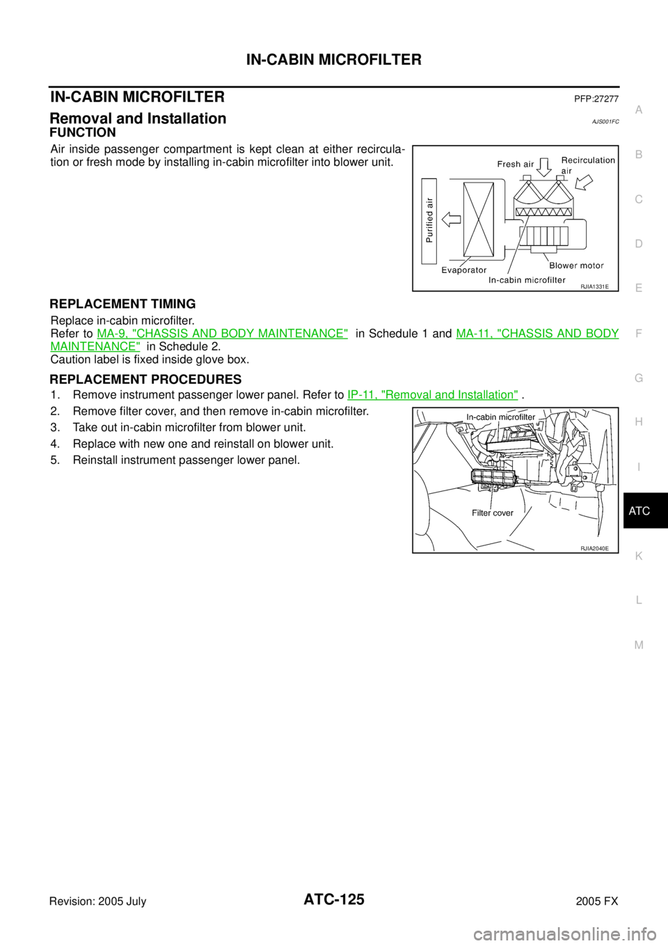
FUNCTION
Air inside passenger compartment is kept clean at either recircula-
tion or fresh mode by installing in-cabin microfilter into blower unit.
REPLACEMENT TIMING
Replace in-cabin microfilter.
Refer to MA-9, "
CHASSIS AND BODY MAINTENANCE" in Schedule 1 and MA-11, "CHASSIS AND BODY
MAINTENANCE" in Schedule 2.
Caution label is fixed inside glove box.
REPLACEMENT PROCEDURES
1. Remove instrument passenger lower panel. Refer to IP-11, "Removal and Installation" .
2. Remove filter cover, and then remove in-cabin microfilter.
3. Take out in-cabin microfilter from blower unit.
4. Replace with new one and reinstall on blower unit.
5. Reinstall instrument passenger lower panel.
RJIA1331E
RJIA2040E