Page 4465 of 4731
SC-30
CHARGING SYSTEM
Revision: 2005 July 2005 FX
DIAGNOSTIC PROCEDURE 1
Check “L” Terminal Circuit (Open)
1. CHECK “L” TERMINAL CONNECTION
1. Turn ignition switch OFF.
2. Check if “L” terminal is clean and tight.
OK or NG
OK >> GO TO 2.
NG >> Repair “L” terminal connection. Confirm repair by performing complete Battery/Starting/Charging system test.
2. CHECK “L” TERMINAL CIRCUIT (OPEN)
1. Disconnect alternator connector.
2. Apply ground to alternator harness connector E311 (VK45DE) or F26 (VQ35DE) terminal 3 (OR) with the ignition switch in the ON
position.
OK or NG
OK >> Go to SC-28, "WORK FLOW" .
NG >> Check the following.
�Charge warning lamp (combination meter)
�Harness for open between combination meter and fuse
�Harness for open between combination meter and alternator
3 (OR) – Ground : Charge warning lamp should
light up.
SKIB0599E
Page 4466 of 4731

CHARGING SYSTEM SC-31
C
D E
F
G H
I
J
L
M A
B
SC
Revision: 2005 July 2005 FX
DIAGNOSTIC PROCEDURE 2
Check “L” Terminal Circuit (Short)
1. CHECK “L” TERMINAL CIRCUIT (SHORT)
1. Turn ignition switch OFF.
2. Disconnect alternator connector.
3. Turn ignition switch ON.
Charge warning lamp should light up?
YES >> Check the following.
�Harness for short between combination meter and alternator
�Charge warning lamp (Combination meter)
NO >> Go to SC-28, "
WORK FLOW" .
DIAGNOSTIC PROCEDURE 3
Check “S” Terminal Circuit
1. CHECK “S” TERMINAL CONNECTION
1. Turn ignition switch OFF.
2. Check if “S” terminal is clean and tight.
OK or NG
OK >> GO TO 2.
NG >> Repair “S” terminal connection. Confirm repair by performing complete Battery/Starting/Charging
system test.
2. CHECK ALTERNATOR “S” TERMINAL CIRCUIT
1. Disconnect alternator connector.
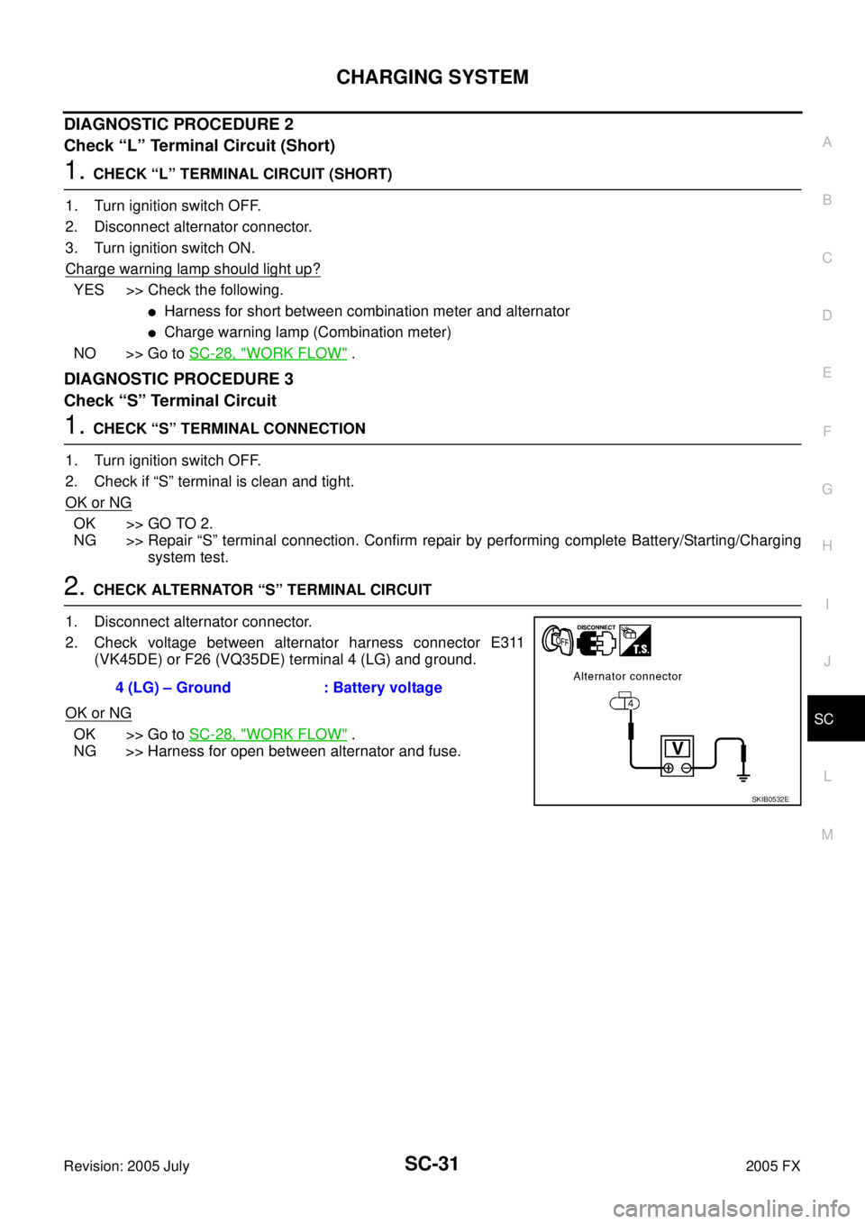
2. Check voltage between alternator harness connector E311 (VK45DE) or F26 (VQ35DE) terminal 4 (LG) and ground.
OK or NG
OK >> Go to SC-28, "WORK FLOW" .
NG >> Harness for open between alternator and fuse. 4 (LG) – Ground : Battery voltage
SKIB0532E
Page 4612 of 4731
TROUBLE DIAGNOSIS SRS-29
C
D E
F
G
I
J
K L
M A
B
SRS
Revision: 2005 July 2005 FX
Trouble Diagnosis without CONSULT-IIAHS000HT
DIAGNOSTIC PROCEDURE 6
Inspecting SRS Malfunctioning Parts by Using “AIR BAG” Warning Lamp — Diagnosis Mode
NOTE:
SRS will not enter Diagnosis mode if no malfunction is detected in User mode.
1. Turn ignition switch ON.
2. After “AIR BAG” warning lamp lights for 7 seconds, turn ignition switch OFF within 1 second.
3. Wait more than 3 seconds.
4. Repeat the steps 1 to 3 twice. (Perform three times in all.)
5. Turn ignition switch ON.
SRS is now in Diagnosis mode.
“AIR BAG” warning lamp operates in Diagnosis mode as follows:
WARNING LAMP FLASH CODE CHART
PHIA0532E
PHIA1233E
SHIA0028E
Page 4653 of 4731

TF-20
TROUBLE DIAGNOSIS
Revision: 2005 July 2005 FX
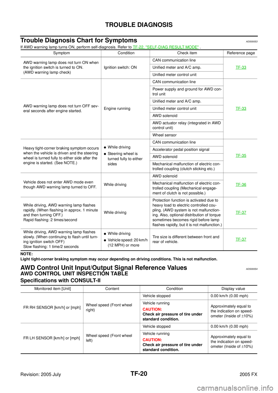
Trouble Diagnosis Chart for SymptomsADS000S3
If AWD warning lamp turns ON, perform self-diagnosis. Refer to TF-22, "SELF-DIAG RESULT MODE" .
NOTE:
Light tight-corner braking symptom may occur depending on driving conditions. This is not malfunction.
AWD Control Unit Input/Output Signal Reference ValuesADS000S4
AWD CONTROL UNIT INSPECTION TABLE
Specifications with CONSULT-II
Symptom Condition Check item Reference page
AWD warning lamp does not turn ON when
the ignition switch is turned to ON.
(AWD warning lamp check) Ignition switch: ON CAN communication line
TF-33
Unified meter and A/C amp.
Unified meter control unit
AWD warning lamp does not turn OFF sev-
eral seconds after engine started. Engine running CAN communication line
TF-33
Power supply and ground for AWD con-
trol unit
Unified meter and A/C amp.
Unified meter control unit
AWD solenoid
AWD actuator relay (integrated in AWD
control unit)
Wheel sensor
Heavy tight-corner braking symptom occurs
when the vehicle is driven and the steering
wheel is turned fully to either side after the
engine is started. (See NOTE.)
�While driving
�Steering wheel is
turned fully to either
sides CAN communication line
TF-35Accelerator pedal position signal
AWD solenoid
Mechanical malfunction of electric con-
trolled coupling (clutch sticking etc.)
Vehicle does not enter AWD mode even
though AWD warning lamp turned to OFF. While driving AWD solenoid
TF-36
Mechanical malfunction of electric con-
trolled coupling (Mechanical engage-
ment of clutch is not possible.)
While driving, AWD warning lamp flashes
rapidly. (When flashing in approx. 1 minute
and then turning OFF.)
Rapid flashing: 2 times/second While driving Protection function is activated due to
heavy load to electric controlled cou-
pling. (AWD system is not malfunction-
ing. Also, optional distribution of torque
sometimes becomes rigid before lamp
flashes rapidly, but it is not malfunction.) TF-37
While driving, AWD warning lamp flashes
slowly. (When continuing to flash until turn-
ing ignition switch OFF)
Slow flashing: 1 time/2 seconds�While driving
�Vehicle speed: 20 km/h
(12 MPH) or more Tire size is different between front and
rear of vehicle. TF-37
Monitored item [Unit] Content Condition Display value
FR RH SENSOR [km/h] or [mph] Wheel speed (Front wheel
right) Vehicle stopped 0.00 km/h (0.00 mph)
Vehicle running
CAUTION:
Check air pressure of tire under
standard condition. Approximately equal to
the indication on speed-
ometer (Inside of ±10%)
FR LH SENSOR [km/h] or [mph] Wheel speed (Front wheel
left) Vehicle stopped 0.00 km/h (0.00 mph)
Vehicle running
CAUTION:
Check air pressure of tire under
standard condition. Approximately equal to
the indication on speed-
ometer (Inside of ±10%)
Page 4669 of 4731

TF-36
TROUBLE DIAGNOSIS FOR SYMPTOMS
Revision: 2005 July 2005 FX
3. CHECK SYSTEM FOR AWD SOLENOID
Perform trouble diagnosis for AWD solenoid system. Refer to TF-28, "
AWD Solenoid" .
OK or NG
OK >> GO TO 4.
NG >> Repair or replace damaged parts.
4. CHECK ELECTRIC CONTROLLED COUPLING
1. Turn ignition switch “OFF”.
2. Set the selector lever to “N” (neutral) position and disengage the parking brake.
3. Lift up the vehicle.
4. Rotate the rear propeller shaft by hand.
5. Hold front propeller shaft lightly.
Does front propeller shaft rotate?
YES >> Replace electric controlled coupling for mechanical malfunction (clutch sticking etc.). Refer to TF-
45, "Disassembly and Assembly" .
NO >> GO TO 5.
5. SYMPTOM CHECK
Check again.
OK or NG
OK >> INSPECTION END
NG >> GO TO 6.
6. CHECK AWD CONTROL UNIT
Check AWD control unit input/output signal. Refer to TF-20, "
AWD Control Unit Input/Output Signal Reference
Va l u e s" .
OK or NG
OK >> INSPECTION END
NG >> Check AWD control unit pin terminals for damage or loose connection with harness connector. If
any items are damaged, repair or replace damaged parts.
Vehicle Does Not Enter AWD Mode Even Though AWD Warning Lamp Turned to
OFF
ADS000U0
DIAGNOSTIC PROCEDURE
1. CHECK AWD SOLENOID
Check AWD solenoid. Refer to TF-30, "
COMPONENT INSPECTION" .
OK or NG
OK >> GO TO 2.
NG >> Replace electric controlled coupling for malfunction of AWD solenoid. Refer to TF-45, "
Disassem-
bly and Assembly" .
2. CHECK AWD CONTROL UNIT
Check AWD control unit input/output signal. Refer to TF-20, "
AWD Control Unit Input/Output Signal Reference
Va l u e s" .
OK or NG
OK >> GO TO 3.
NG >> Check AWD control unit pin terminals for damage or loose connection with harness connector. If any items are damaged, repair or replace damaged parts.