Page 249 of 4731

AT-166
DTC P1772 LOW COAST BRAKE SOLENOID VALVE
Revision: 2005 July 2005 FX
DTC P1772 LOW COAST BRAKE SOLENOID VALVEPFP:31940
DescriptionACS002Q0
Low coast brake solenoid valve is turned ON or OFF by the TCM in response to signals sent from the PNP
switch, vehicle speed sensor and accelerator pedal position sensor (throttle position sensor). Gears will then
be shifted to the optimum position.
CONSULT-II Reference ValueACS003KP
On Board Diagnosis LogicACS002Q1
�This is an OBD-II self-diagnostic item.
�Diagnostic trouble code “P1772 LC/B SOLENOID/CIRC” with CONSULT-II or 7th judgement flicker with-
out CONSULT-II is detected when TCM detects an improper voltage drop when it tries to operate the sole-
noid valve.
Possible CauseACS002Q2
�Harness or connectors
(Solenoid circuit is open or shorted.)
�Low coast brake solenoid valve
DTC Confirmation ProcedureACS002Q3
NOTE:
If “DTC Confirmation Procedure” has been previously performed, always turn ignition switch OFF and
wait at least 10 seconds before performing the next test.
After the repair, perform the following procedure to confirm the malfunction is eliminated.
WITH CONSULT-II
1. Turn ignition switch ON. (Do not start engine.)
2. Select “MAIN SIGNALS” in “DATA MONITOR” mode for “A/T” with CONSULT-II.
3. Touch “START”.
4. Start engine.
5. Drive vehicle and maintain the following conditions for at least 5 consecutive seconds.
Selector lever: “M” position
Gear position: “M1-1st” or “M2-2nd” gear (LC/B ON/OFF)
6. If DTC is detected, go to AT- 1 6 7 , "
Diagnostic Procedure" .
WITH GST
Follow the procedure “WITH CONSULT-II”.
Item name Condition Display value
ON OFF SOL Low coast brake engaged. Refer to
AT- 2 1
.ON
Low coast brake disengaged. Refer to AT- 2 1
.OFF
BCIA0031E
Page 250 of 4731

DTC P1772 LOW COAST BRAKE SOLENOID VALVE AT-167
D E
F
G H
I
J
K L
M A
B
AT
Revision: 2005 July 2005 FX
Diagnostic ProcedureACS002Q4
1. CHECK INPUT SIGNAL
With CONSULT-II
1. Turn ignition switch ON. (Do not start engine.)
2. Select “SELECTION FROM MENU” in “DATA MONITOR” mode for “A/T” with CONSULT-II.
3. Start engine.
4. Read out the value of “ON OFF SOL” while driving.
OK or NG
OK >> GO TO 4.
NG >> GO TO 2.
2. CHECK TCM POWER SUPPLY AND GROUND CIRCUIT
Check TCM power supply and ground circuit. Refer to AT- 1 8 3 , "
MAIN POWER SUPPLY AND GROUND CIR-
CUIT" .
OK or NG
OK >> GO TO 3.
NG >> Repair or replace damaged parts.
3. DETECT MALFUNCTIONING ITEM
Check the following.
�The A/T assembly harness connector pin terminals for damage or loose connection with harness connec-
tor.
OK or NG
OK >> Replace the control valve with TCM. Refer to AT- 2 4 3 , "Control Valve with TCM and A/T Fluid Tem-
perature Sensor 2" .
NG >> Repair or replace damaged parts.
4. CHECK DTC
Perform “DTC Confirmation Procedure”.
�Refer to AT- 1 6 6 , "DTC Confirmation Procedure" .
OK or NG
OK >> INSPECTION END
NG >> GO TO 2.
Item name Condition Display value
ON OFF SOL Low coast brake engaged. Refer to
AT- 2 1
.ON
Low coast brake disengaged. Refer to AT- 2 1
.OFF
SCIA4794E
Page 251 of 4731

AT-168
DTC P1774 LOW COAST BRAKE SOLENOID VALVE FUNCTION
Revision: 2005 July 2005 FX
DTC P1774 LOW COAST BRAKE SOLENOID VALVE FUNCTIONPFP:31940
DescriptionACS002Q5
�Low coast brake solenoid valve is turned ON or OFF by the TCM in response to signals sent from the
PNP switch, vehicle speed sensor and accelerator pedal position sensor (throttle position sensor). Gears
will then be shifted to the optimum position.
�This is not only caused by electrical malfunction (circuits open or shorted) but also by mechanical mal-
function such as control valve sticking, improper solenoid valve operation.
CONSULT-II Reference ValueACS003KQ
On Board Diagnosis LogicACS002Q6
�This is an OBD-II self-diagnostic item.
�Diagnostic trouble code “P1774 LC/B SOLENOID FNCT” with CONSULT-II or 7th judgement flicker with-
out CONSULT-II is detected under the following conditions.
–When TCM detects that actual gear ratio is irregular, and relation between gear position and condition of
ATF pressure switch 2 is irregular during depressing accelerator pedal. (Other than during shift change)
–When TCM detects that relation between gear position and condition of ATF pressure switch 2 is irregular
during releasing accelerator pedal. (Other than during shift change)
Possible CauseACS002Q7
�Harness or connectors
(Solenoid and switch circuits are open or shorted.)
�Low coast brake solenoid valve
�ATF pressure switch 2
DTC Confirmation ProcedureACS002Q8
CAUTION:
Always drive vehicle at a safe speed.
NOTE:
If “DTC Confirmation Procedure” has been previously performed, always turn ignition switch “OFF”
and wait at least 10 seconds before performing the next test.
After the repair, perform the following procedure to confirm the malfunction is eliminated.
WITH CONSULT-II
1. Start engine.
2. Accelerate vehicle to maintain the following conditions. Selector lever: “M” position
Gear position: “M1-1st” or “M2-2nd” gear (LC/B ON/OFF)
3. Perform step “2” again.
4. Turn ignition switch OFF, then perform step “1” to “3” again.
5. Check “SELF-DIAG RESULTS” mode for “A/T” with CONSULT- II. If DTC (P1774) is detected, go to AT- 1 6 9 , "
Diagnostic Proce-
dure" .
If DTC (P1772) is detected, go to AT- 1 6 7 , "
Diagnostic Proce-
dure" .
WITH GST
Follow the procedure “WITH CONSULT-II”.
Item name Condition Display value
ON OFF SOL Low coast brake engaged. Refer to
AT- 2 1
.ON
Low coast brake disengaged. Refer to AT- 2 1
.OFF
ATF PRES SW 2 Low coast brake engaged. Refer to
AT- 2 1
.ON
Low coast brake disengaged. Refer to AT- 2 1
.OFF
BCIA0031E
Page 252 of 4731

DTC P1774 LOW COAST BRAKE SOLENOID VALVE FUNCTION AT-169
D E
F
G H
I
J
K L
M A
B
AT
Revision: 2005 July 2005 FX
Diagnostic ProcedureACS002Q9
1. CHECK INPUT SIGNALS
With CONSULT-II
1. Start engine.
2. Select “SELECTION FROM MENU” in “DATA MONITOR” mode for “A/T” with CONSULT-II.
3. Drive vehicle in the manual mode (“M1-1st” or “M2-2nd” gear), and confirm the ON/OFF actuation of the “ATF PRES SW 2” and
“ON OFF SOL”.
OK or NG
OK >> GO TO 4.
NG >> GO TO 2.
2. CHECK TCM POWER SUPPLY AND GROUND CIRCUIT
Check TCM power supply and ground circuit. Refer to AT- 1 8 3 , "
MAIN POWER SUPPLY AND GROUND CIR-
CUIT" .
OK or NG
OK >> GO TO 3.
NG >> Repair or replace damaged parts.
3. DETECT MALFUNCTIONING ITEM
Check the following.
�The A/T assembly harness connector pin terminals for damage or loose connection with harness connec-
tor.
OK or NG
OK >> Replace the control valve with TCM. Refer to AT- 2 4 3 , "Control Valve with TCM and A/T Fluid Tem-
perature Sensor 2" .
NG >> Repair or replace damaged parts.
4. CHECK DTC
Perform “DTC Confirmation Procedure”.
�Refer to AT- 1 6 8 , "DTC Confirmation Procedure" .
OK or NG
OK >> INSPECTION END
NG >> GO TO 2.
Item name Condition Display value
ON OFF SOL Low coast brake engaged. Refer to
AT- 2 1
.ON
Low coast brake disengaged. Refer to AT- 2 1
.OFF
ATF PRES SW 2 Low coast brake engaged. Refer to
AT- 2 1
.ON
Low coast brake disengaged. Refer to AT- 2 1
.OFF
SCIA4794E
Page 259 of 4731

AT-176
DTC P1841 ATF PRESSURE SWITCH 1
Revision: 2005 July 2005 FX
Diagnostic ProcedureACS002QM
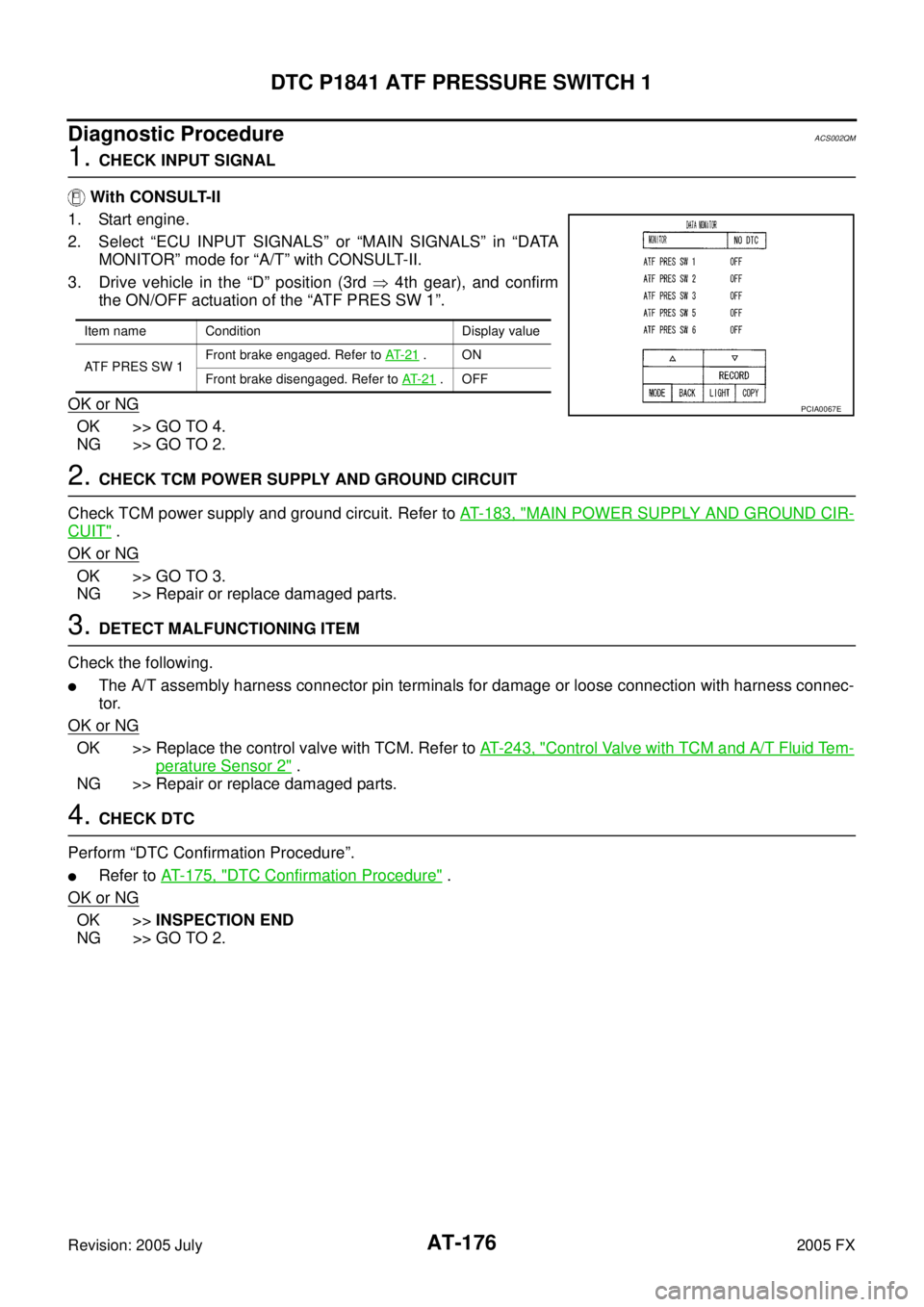
1. CHECK INPUT SIGNAL
With CONSULT-II
1. Start engine.
2. Select “ECU INPUT SIGNALS” or “MAIN SIGNALS” in “DATA MONITOR” mode for “A/T” with CONSULT-II.
3. Drive vehicle in the “D” position (3rd � 4th gear), and confirm
the ON/OFF actuation of the “ATF PRES SW 1”.
OK or NG
OK >> GO TO 4.
NG >> GO TO 2.
2. CHECK TCM POWER SUPPLY AND GROUND CIRCUIT
Check TCM power supply and ground circuit. Refer to AT- 1 8 3 , "
MAIN POWER SUPPLY AND GROUND CIR-
CUIT" .
OK or NG
OK >> GO TO 3.
NG >> Repair or replace damaged parts.
3. DETECT MALFUNCTIONING ITEM
Check the following.
�The A/T assembly harness connector pin terminals for damage or loose connection with harness connec-
tor.
OK or NG
OK >> Replace the control valve with TCM. Refer to AT- 2 4 3 , "Control Valve with TCM and A/T Fluid Tem-
perature Sensor 2" .
NG >> Repair or replace damaged parts.
4. CHECK DTC
Perform “DTC Confirmation Procedure”.
�Refer to AT- 1 7 5 , "DTC Confirmation Procedure" .
OK or NG
OK >> INSPECTION END
NG >> GO TO 2.
Item name Condition Display value
ATF PRES SW 1 Front brake engaged. Refer to
AT- 2 1
.ON
Front brake disengaged. Refer to AT- 2 1
.OFF
PCIA0067E
Page 385 of 4731

AT-302
DISASSEMBLY
Revision: 2005 July 2005 FX
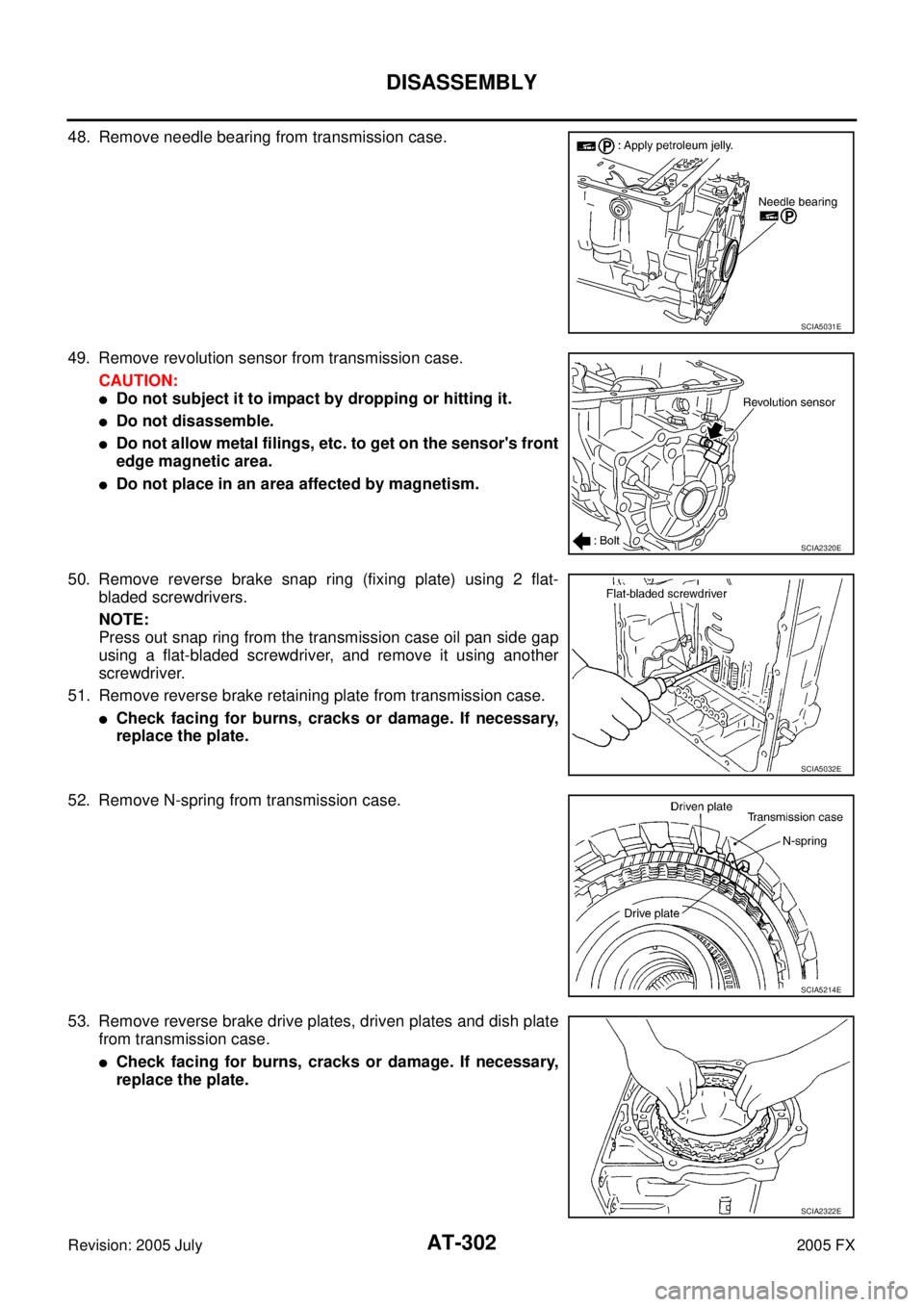
48. Remove needle bearing from transmission case.
49. Remove revolution sensor from transmission case. CAUTION:
�Do not subject it to impact by dropping or hitting it.
�Do not disassemble.
�Do not allow metal filings, etc. to get on the sensor's front
edge magnetic area.
�Do not place in an area affected by magnetism.
50. Remove reverse brake snap ring (fixing plate) using 2 flat- bladed screwdrivers.
NOTE:
Press out snap ring from the transmission case oil pan side gap
using a flat-bladed screwdriver, and remove it using another
screwdriver.
51. Remove reverse brake retaining plate from transmission case.
�Check facing for burns, cracks or damage. If necessary,
replace the plate.
52. Remove N-spring from transmission case.
53. Remove reverse brake drive plates, driven plates and dish plate from transmission case.
�Check facing for burns, cracks or damage. If necessary,
replace the plate.
SCIA5031E
SCIA2320E
SCIA5032E
SCIA5214E
SCIA2322E
Page 416 of 4731
ASSEMBLY AT-333
D E
F
G H
I
J
K L
M A
B
AT
Revision: 2005 July 2005 FX
22. Measure clearance between retaining plate and snap ring. If not
within specified clearance, select proper retaining plate.
23. Install needle bearing to transmission case. CAUTION:
Apply petroleum jelly to needle bearing.
24. Install revolution sensor to transmission case. CAUTION:
�Do not subject it to impact by dropping or hitting it.
�Do not disassemble.
�Do not allow metal filings, etc., to get on the sensor's
front edge magnetic area.
�Do not place in an area affected by magnetism.
25. As shown in the figure, use the drift to drive rear oil seal into the rear extension (2WD models) or adapter case (AWD models)
until it is flush.
CAUTION:
�Apply ATF to rear oil seal.
�Do not reuse rear oil seal. Specified clearance “A”:
Standard: 0.7 - 1.1mm (0.028 - 0.043 in)
Retaining plate: Refer to AT- 3 5 3 , "
Reverse Brake" .
SCIA3129E
SCIA5031E
: 5.8 N·m (0.59 kg-m, 51 in-lb)
SCIA2320E
SCIA5477E
Page 428 of 4731
ASSEMBLY AT-345
D E
F
G H
I
J
K L
M A
B
AT
Revision: 2005 July 2005 FX
6. Install O-ring to input clutch assembly.
CAUTION:
�Do not reuse O-ring.
�Apply ATF to O-ring.
7. Install converter housing to transmission case. CAUTION:
Do not reuse self-sealing bolt.
8. Make sure that brake band does not close turbine revolution sensor hole.
9. Install control valve with TCM.
a. Connect TCM connector and park/neutral position switch con- nector.
SCIA5011E
Converter housing mounting bolt:
: 52 N·m (5.3 kg-m, 38 ft-lb)
Self-sealing bolt: : 61 N·m (6.2 kg-m, 45 ft-lb)
SCIA3427E
SCIA5034E
SCIA5449E