2005 INFINITI FX35 air condition
[x] Cancel search: air conditionPage 4533 of 4731
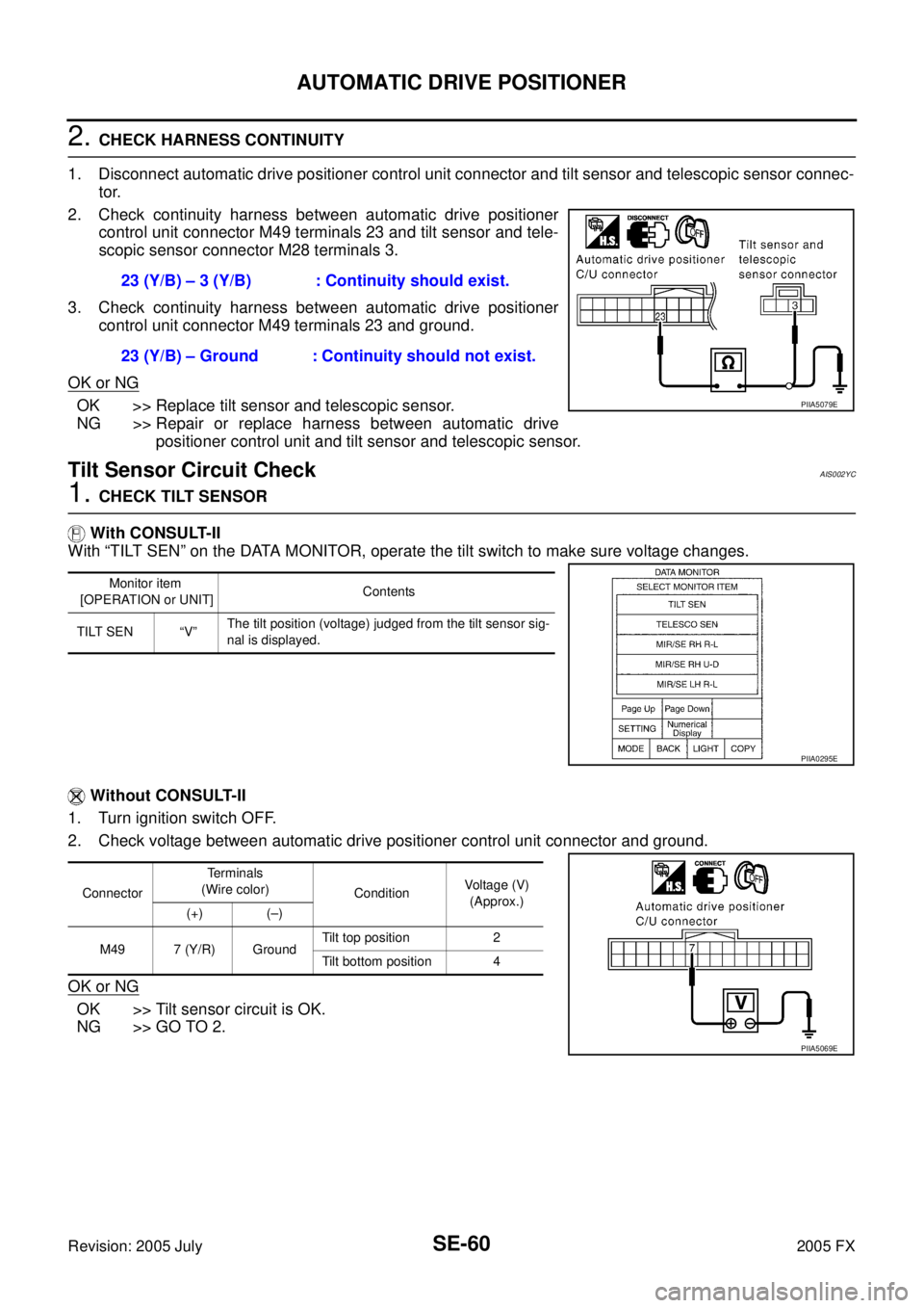
SE-60
AUTOMATIC DRIVE POSITIONER
Revision: 2005 July 2005 FX
2. CHECK HARNESS CONTINUITY
1. Disconnect automatic drive positioner control unit connector and tilt sensor and telescopic sensor connec- tor.
2. Check continuity harness between automatic drive positioner control unit connector M49 terminals 23 and tilt sensor and tele-
scopic sensor connector M28 terminals 3.
3. Check continuity harness between automatic drive positioner control unit connector M49 terminals 23 and ground.
OK or NG
OK >> Replace tilt sensor and telescopic sensor.
NG >> Repair or replace harness between automatic drive positioner control unit and tilt sensor and telescopic sensor.
Tilt Sensor Circuit CheckAIS002YC
1. CHECK TILT SENSOR
With CONSULT-II
With “TILT SEN” on the DATA MONITOR, operate the tilt switch to make sure voltage changes.
Without CONSULT-II
1. Turn ignition switch OFF.
2. Check voltage between automatic drive positioner control unit connector and ground.
OK or NG
OK >> Tilt sensor circuit is OK.
NG >> GO TO 2. 23 (Y/B) – 3 (Y/B) : Continuity should exist.
23 (Y/B) – Ground : Continuity should not exist.
PIIA5079E
Monitor item
[OPERATION or UNIT] Contents
TILT SEN “V” The tilt position (voltage) judged from the tilt sensor sig-
nal is displayed.
PIIA0295E
Connector Terminals
(Wire color) Condition Voltage (V)
(Approx.)
(+) (–)
M49 7 (Y/R) Ground Tilt top position 2
Tilt bottom position 4
PIIA5069E
Page 4535 of 4731
SE-62
AUTOMATIC DRIVE POSITIONER
Revision: 2005 July 2005 FX
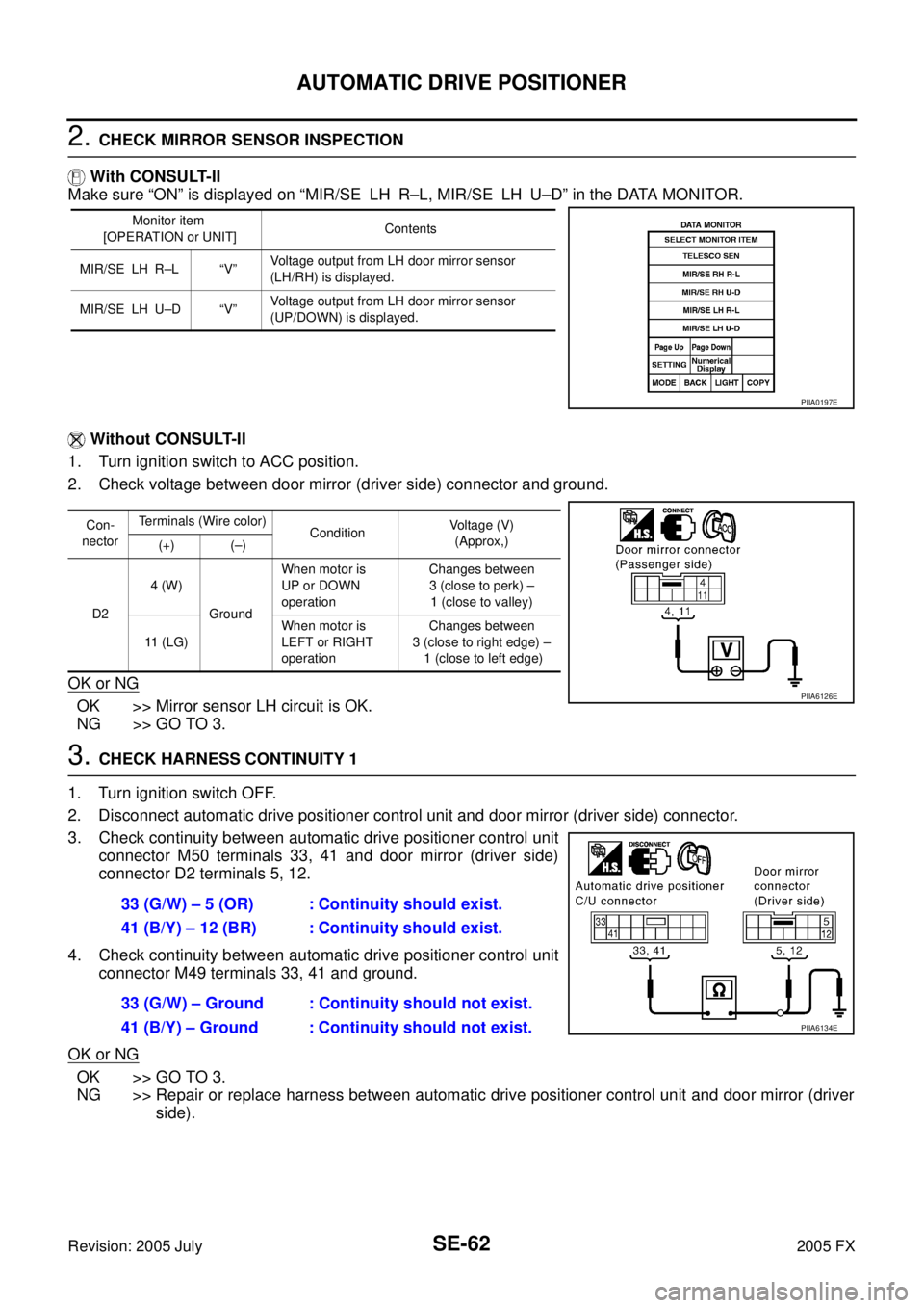
2. CHECK MIRROR SENSOR INSPECTION
With CONSULT-II
Make sure “ON” is displayed on “MIR/SE LH R–L, MIR/SE LH U–D” in the DATA MONITOR.
Without CONSULT-II
1. Turn ignition switch to ACC position.
2. Check voltage between door mirror (driver side) connector and ground.
OK or NG
OK >> Mirror sensor LH circuit is OK.
NG >> GO TO 3.
3. CHECK HARNESS CONTINUITY 1
1. Turn ignition switch OFF.
2. Disconnect automatic drive positioner control unit and door mirror (driver side) connector.
3. Check continuity between automatic drive positioner control unit connector M50 terminals 33, 41 and door mirror (driver side)
connector D2 terminals 5, 12.
4. Check continuity between automatic drive positioner control unit connector M49 terminals 33, 41 and ground.
OK or NG
OK >> GO TO 3.
NG >> Repair or replace harness between automatic drive positioner control unit and door mirror (driver side).
Monitor item
[OPERATION or UNIT] Contents
MIR/SE LH R–L “V” Voltage output from LH door mirror sensor
(LH/RH) is displayed.
MIR/SE LH U–D “V” Voltage output from LH door mirror sensor
(UP/DOWN) is displayed.
PIIA0197E
Con-
nector Terminals (Wire color)
Condition Voltage (V)
(Approx,)
(+) (–)
D2 4 (W)
Ground When motor is
UP or DOWN
operation Changes between
3 (close to perk) –
1 (close to valley)
11 (LG) When motor is
LEFT or RIGHT
operation Changes between
3 (close to right edge) – 1 (close to left edge)
PIIA6126E
33 (G/W) – 5 (OR) : Continuity should exist.
41 (B/Y) – 12 (BR) : Continuity should exist.
33 (G/W) – Ground : Continuity should not exist.
41 (B/Y) – Ground : Continuity should not exist.
PIIA6134E
Page 4536 of 4731
AUTOMATIC DRIVE POSITIONER SE-63
C
D E
F
G H
J
K L
M A
B
SE
Revision: 2005 July 2005 FX
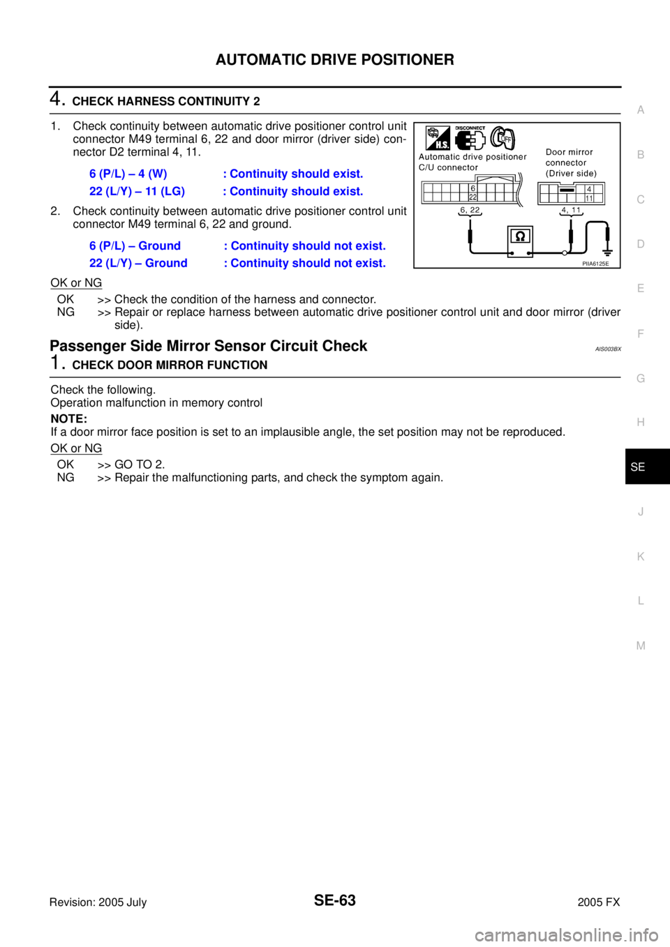
4. CHECK HARNESS CONTINUITY 2
1. Check continuity between automatic drive positioner control unit connector M49 terminal 6, 22 and door mirror (driver side) con-
nector D2 terminal 4, 11.
2. Check continuity between automatic drive positioner control unit connector M49 terminal 6, 22 and ground.
OK or NG
OK >> Check the condition of the harness and connector.
NG >> Repair or replace harness between automatic drive positioner control unit and door mirror (driver
side).
Passenger Side Mirror Sensor Circuit Check AIS003BX
1. CHECK DOOR MIRROR FUNCTION
Check the following.
Operation malfunction in memory control
NOTE:
If a door mirror face position is set to an implausible angle, the set position may not be reproduced.
OK or NG
OK >> GO TO 2.
NG >> Repair the malfunctioning parts, and check the symptom again. 6 (P/L) – 4 (W) : Continuity should exist.
22 (L/Y) – 11 (LG) : Continuity should exist.
6 (P/L) – Ground : Continuity should not exist.
22 (L/Y) – Ground : Continuity should not exist.
PIIA6125E
Page 4537 of 4731
SE-64
AUTOMATIC DRIVE POSITIONER
Revision: 2005 July 2005 FX
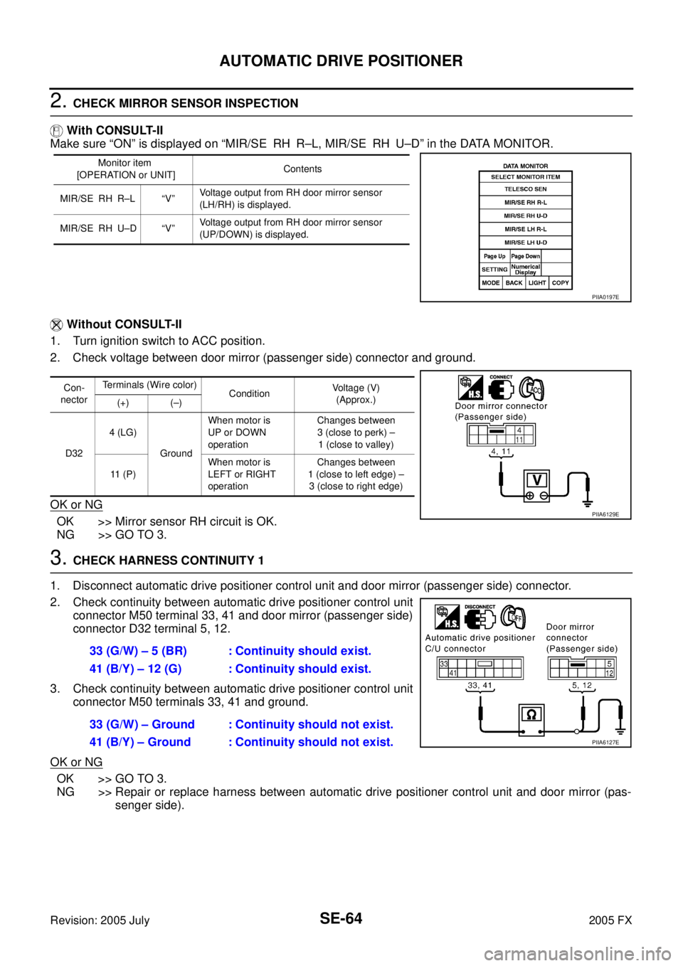
2. CHECK MIRROR SENSOR INSPECTION
With CONSULT-II
Make sure “ON” is displayed on “MIR/SE RH R–L, MIR/SE RH U–D” in the DATA MONITOR.
Without CONSULT-II
1. Turn ignition switch to ACC position.
2. Check voltage between door mirror (passenger side) connector and ground.
OK or NG
OK >> Mirror sensor RH circuit is OK.
NG >> GO TO 3.
3. CHECK HARNESS CONTINUITY 1
1. Disconnect automatic drive positioner control unit and door mirror (passenger side) connector.
2. Check continuity between automatic drive positioner control unit connector M50 terminal 33, 41 and door mirror (passenger side)
connector D32 terminal 5, 12.
3. Check continuity between automatic drive positioner control unit connector M50 terminals 33, 41 and ground.
OK or NG
OK >> GO TO 3.
NG >> Repair or replace harness between automatic drive positioner control unit and door mirror (pas- senger side).
Monitor item
[OPERATION or UNIT] Contents
MIR/SE RH R–L “V” Voltage output from RH door mirror sensor
(LH/RH) is displayed.
MIR/SE RH U–D “V” Voltage output from RH door mirror sensor
(UP/DOWN) is displayed.
PIIA0197E
Con-
nector Terminals (Wire color)
Condition Voltage (V)
(Approx.)
(+) (–)
D32 4 (LG)
Ground When motor is
UP or DOWN
operation Changes between
3 (close to perk) –
1 (close to valley)
11 ( P ) When motor is
LEFT or RIGHT
operation Changes between
1 (close to left edge) – 3 (close to right edge)
PIIA6129E
33 (G/W) – 5 (BR) : Continuity should exist.
41 (B/Y) – 12 (G) : Continuity should exist.
33 (G/W) – Ground : Continuity should not exist.
41 (B/Y) – Ground : Continuity should not exist.
PIIA6127E
Page 4538 of 4731

AUTOMATIC DRIVE POSITIONER SE-65
C
D E
F
G H
J
K L
M A
B
SE
Revision: 2005 July 2005 FX
4. CHECK HARNESS CONTINUITY 2
1. Check continuity between automatic drive positioner control unit connector M49 terminal 5, 21 and door mirror (passenger side)
connector D32 terminal 4, 11.
2. Check continuity between automatic drive positioner control unit connector M49 terminal 5, 21 and ground.
OK or NG
OK >> Check the condition of the harness and connector.
NG >> Repair or replace harness between automatic drive positioner control unit and door mirror (pas-
senger side).
Steering and Door Mirror Sensor Power and Ground Circuit CheckAIS003GA
1. CHECK MIRROR SENSOR POWER SUPPLY
1. Turn ignition switch OFF.
2. Check voltage between automatic drive positioner control unit connector M50 terminal 33 and ground.
OK or NG
OK >> GO TO 2.
NG >> Replace automatic drive positioner control unit.
2. CHECK MIRROR SENSOR GROUND CIRCUIT
Check continuity between automatic drive positioner control unit
connector M50 terminal 41 and ground.
OK or NG
OK >> GO TO 3.
NG >> Replace automatic drive positioner control unit. 5 (OR) – 4 (LG) : Continuity should exist.
21 (G/Y) – 11 (P) : Continuity should exist.
5 (OR) – Ground : Continuity should not exist.
21 (G/Y) – Ground : Continuity should not exist.
PIIA6128E
33 (G/W) – Ground : Approx. 5V
PIIA4778E
41 (B/Y) – Ground : Continuity should exist.
PIIA4779E
Page 4539 of 4731
SE-66
AUTOMATIC DRIVE POSITIONER
Revision: 2005 July 2005 FX
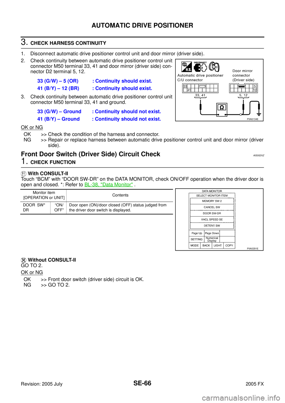
3. CHECK HARNESS CONTINUITY
1. Disconnect automatic drive positioner control unit and door mirror (driver side).
2. Check continuity between automatic drive positioner control unit connector M50 terminal 33, 41 and door mirror (driver side) con-
nector D2 terminal 5, 12.
3. Check continuity between automatic drive positioner control unit connector M50 terminal 33, 41 and ground.
OK or NG
OK >> Check the condition of the harness and connector.
NG >> Repair or replace harness between automatic drive positioner control unit and door mirror (driver side).
Front Door Switch (Driver Side) Circuit CheckAIS002XZ
1. CHECK FUNCTION
With CONSULT-II
Touch “BCM” with “DOOR SW-DR” on the DATA MONITOR, check ON/OFF operation when the driver door is
open and closed. *: Refer to BL-38, "
Data Monitor" .
Without CONSULT-II
GO TO 2.
OK or NG
OK >> Front door switch (driver side) circuit is OK.
NG >> GO TO 2. 33 (G/W) – 5 (OR) : Continuity should exist.
41 (B/Y) – 12 (BR) : Continuity should exist.
33 (G/W) – Ground : Continuity should not exist.
41 (B/Y) – Ground : Continuity should not exist.
PIIA6134E
Monitor item
[OPERATION or UNIT] Contents
DOOR SW*
DR “ON/
OFF” Door open (ON)/door closed (OFF) status judged from
the driver door switch is displayed.
PIIA0291E
Page 4541 of 4731
SE-68
AUTOMATIC DRIVE POSITIONER
Revision: 2005 July 2005 FX
Sliding Switch Circuit CheckAIS002Y1
1. CHECK FUNCTION
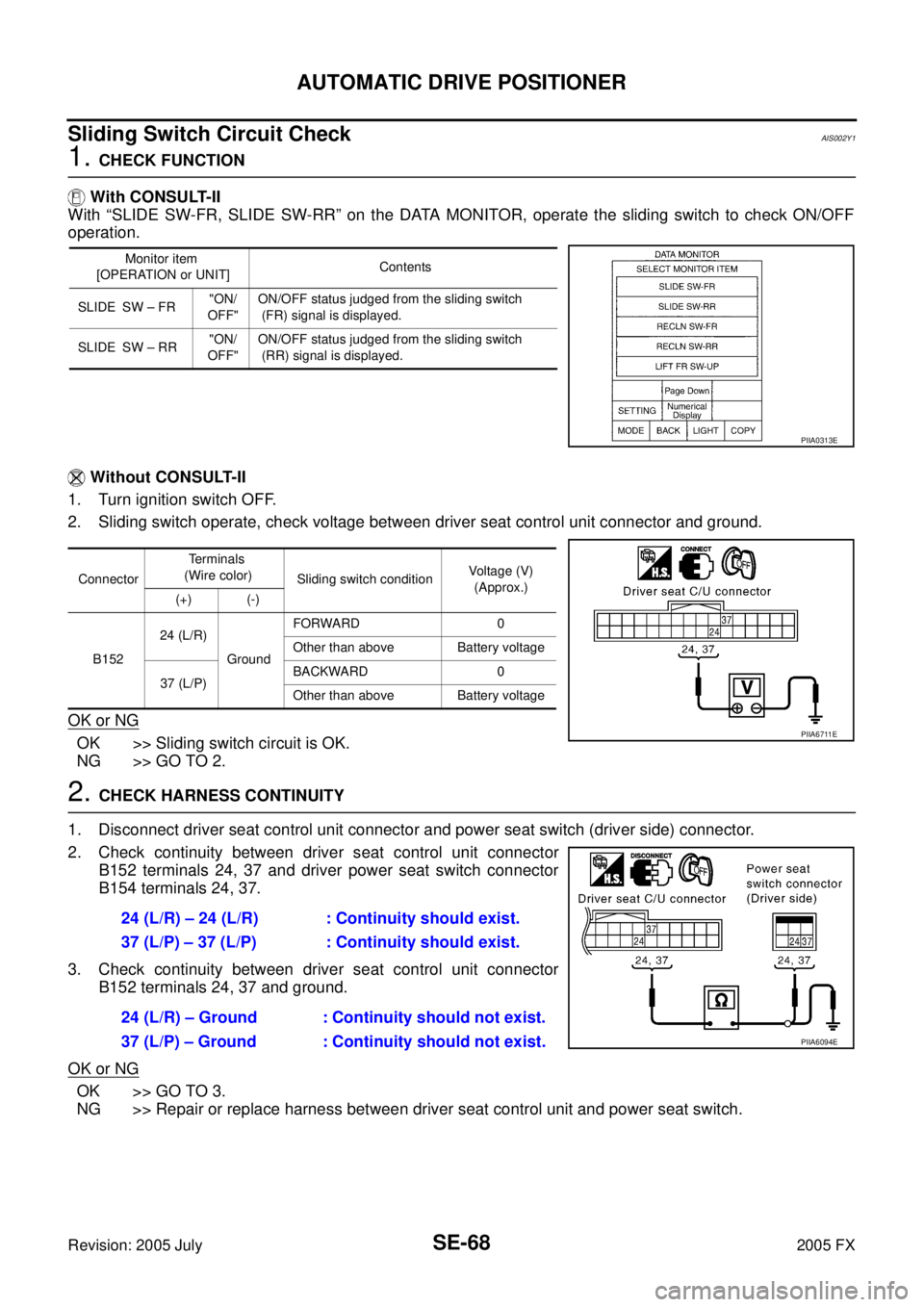
With CONSULT-II
With “SLIDE SW-FR, SLIDE SW-RR” on the DATA MONITOR, operate the sliding switch to check ON/OFF
operation.
Without CONSULT-II
1. Turn ignition switch OFF.
2. Sliding switch operate, check voltage between driver seat control unit connector and ground.
OK or NG
OK >> Sliding switch circuit is OK.
NG >> GO TO 2.
2. CHECK HARNESS CONTINUITY
1. Disconnect driver seat control unit connector and power seat switch (driver side) connector.
2. Check continuity between driver seat control unit connector B152 terminals 24, 37 and driver power seat switch connector
B154 terminals 24, 37.
3. Check continuity between driver seat control unit connector B152 terminals 24, 37 and ground.
OK or NG
OK >> GO TO 3.
NG >> Repair or replace harness between driver seat control unit and power seat switch.
Monitor item
[OPERATION or UNIT] Contents
SLIDE SW – FR "ON/
OFF" ON/OFF status judged from the sliding switch
(FR) signal is displayed.
SLIDE SW – RR "ON/
OFF" ON/OFF status judged from the sliding switch
(RR) signal is displayed.
PIIA0313E
Connector Terminals
(Wire color) Sliding switch condition Voltage (V)
(Approx.)
(+) (-)
B152 24 (L/R)
Ground FORWARD 0
Other than above Battery voltage
37 (L/P) BACKWARD 0
Other than above Battery voltage
PIIA6711E
24 (L/R) – 24 (L/R) : Continuity should exist.
37 (L/P) – 37 (L/P) : Continuity should exist.
24 (L/R) – Ground : Continuity should not exist.
37 (L/P) – Ground : Continuity should not exist.
PIIA6094E
Page 4543 of 4731
SE-70
AUTOMATIC DRIVE POSITIONER
Revision: 2005 July 2005 FX
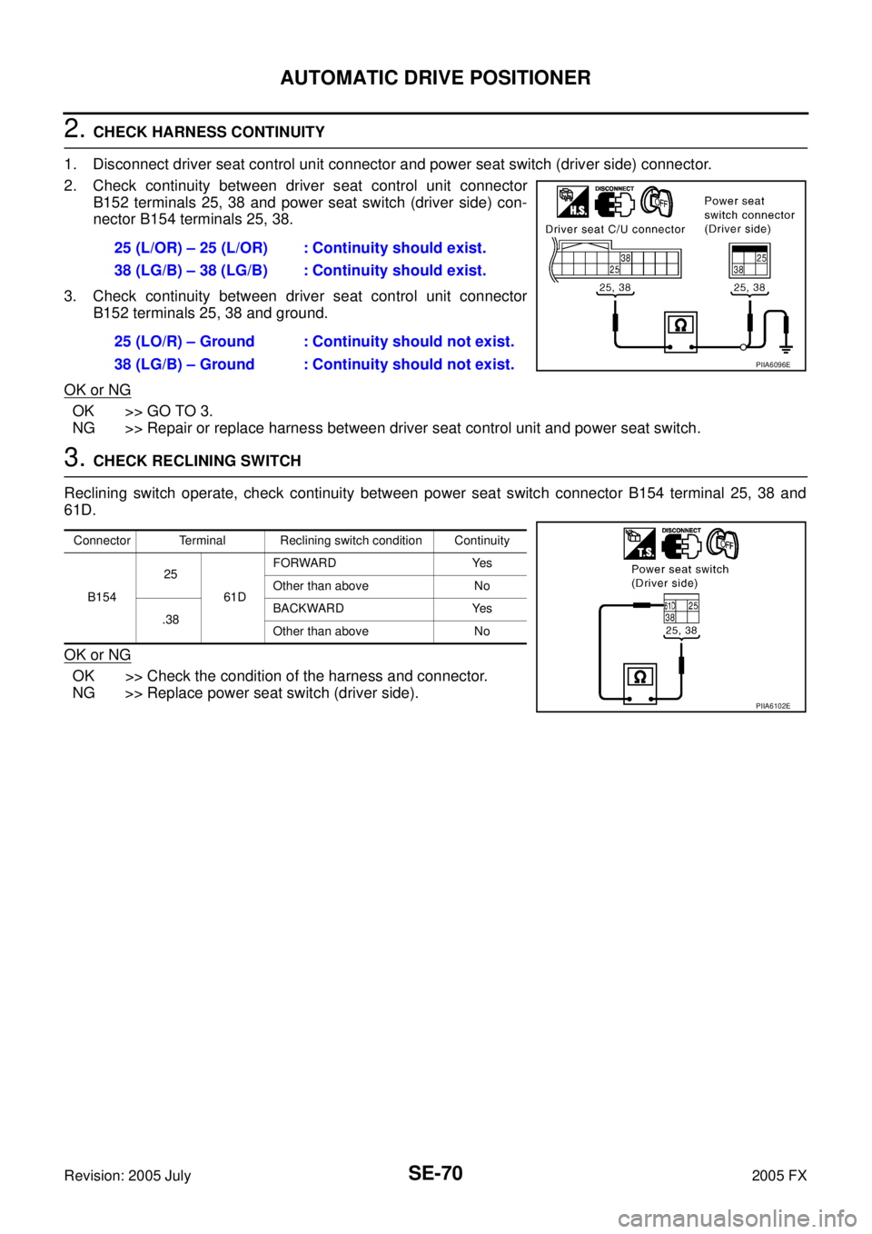
2. CHECK HARNESS CONTINUITY
1. Disconnect driver seat control unit connector and power seat switch (driver side) connector.
2. Check continuity between driver seat control unit connector B152 terminals 25, 38 and power seat switch (driver side) con-
nector B154 terminals 25, 38.
3. Check continuity between driver seat control unit connector B152 terminals 25, 38 and ground.
OK or NG
OK >> GO TO 3.
NG >> Repair or replace harness between driver seat control unit and power seat switch.
3. CHECK RECLINING SWITCH
Reclining switch operate, check continuity between power seat switch connector B154 terminal 25, 38 and
61D.
OK or NG
OK >> Check the condition of the harness and connector.
NG >> Replace power seat switch (driver side). 25 (L/OR) – 25 (L/OR) : Continuity should exist.
38 (LG/B) – 38 (LG/B) : Continuity should exist.
25 (LO/R) – Ground : Continuity should not exist.
38 (LG/B) – Ground : Continuity should not exist.
PIIA6096E
Connector Terminal Reclining switch condition Continuity
B154 25
61D FORWARD Yes
Other than above No
.38 BACKWARD Yes
Other than above No
PIIA6102E