Page 3167 of 4731
FFD-16
FRONT FINAL DRIVE ASSEMBLY
Revision: 2005 July 2005 FX
Disassembly and AssemblyADS0019Y
COMPONENTS (VQ35DE MODELS)
1. Drive pinion lock nut 2. Companion flange 3. Front oil seal
4. Pinion front bearing 5. Drive pinion bearing adjusting washer 6. Drive pinion adjusting washer
7. Gear carrier 8. Pinion rear bearing 9. Pinion height adjusting washer
10. Drive pinion 11. Drive gear 12. Side oil seal (right side)
13. Side retainer 14. O-ring 15. Side bearing adjusting shim
16. Side bearing 17. Differential case 18. Breather connector
19. Dowel pin 20. Filler plug 21. Drain plug
22. Gasket 23. Carrier cover 24. Gear oil defence
25. Side gear thrust washer 26. Side gear 27. Circular clip
28. Pinion mate thrust washer 29. Pinion mate gear 30. Pinion mate shaft
31. Lock pin 32. Side bearing adjusting washer 33. Side oil seal (left side)
PDIA0662E
Page 3169 of 4731
FFD-18
FRONT FINAL DRIVE ASSEMBLY
Revision: 2005 July 2005 FX
COMPONENTS (VK45DE MODELS)
1. Drive pinion lock nut 2. Companion flange 3. Front oil seal
4. Pinion front bearing 5. Drive pinion bearing adjusting washer 6. Drive pinion adjusting washer
7. Gear carrier 8. Pinion rear bearing 9. Pinion height adjusting washer
10. Drive pinion 11. Drive gear 12. Side oil seal (right side)
13. Side retainer 14. O-ring 15. Side bearing adjusting shim
16. Side bearing 17. Differential case 18. Breather connector
19. Dowel pin 20. Filler plug 21. Drain plug
22. Gasket 23. Carrier cover 24. Gear oil defence
25. Side gear thrust washer 26. Side gear 27. Circular clip
28. Pinion mate thrust washer 29. Pinion mate gear 30. Pinion mate shaft
31. Lock pin 32. Side bearing adjusting washer 33. Side oil seal (left side)
PDIA0663E
Page 3177 of 4731
FFD-26
FRONT FINAL DRIVE ASSEMBLY
Revision: 2005 July 2005 FX
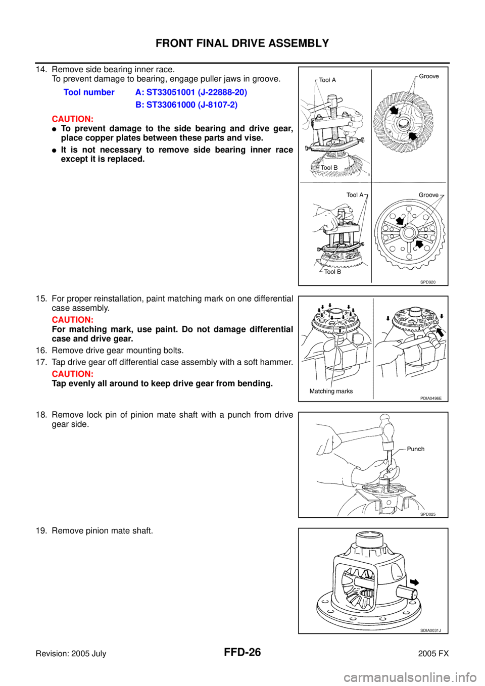
14. Remove side bearing inner race.
To prevent damage to bearing, engage puller jaws in groove.
CAUTION:
�To prevent damage to the side bearing and drive gear,
place copper plates between these parts and vise.
�It is not necessary to remove side bearing inner race
except it is replaced.
15. For proper reinstallation, paint matching mark on one differential case assembly.
CAUTION:
For matching mark, use paint. Do not damage differential
case and drive gear.
16. Remove drive gear mounting bolts.
17. Tap drive gear off differential case assembly with a soft hammer. CAUTION:
Tap evenly all around to keep drive gear from bending.
18. Remove lock pin of pinion mate shaft with a punch from drive gear side.
19. Remove pinion mate shaft. Tool number A: ST33051001 (J-22888-20)
B: ST33061000 (J-8107-2)
SPD920
PDIA0496E
SPD025
SDIA0031J
Page 3178 of 4731
FRONT FINAL DRIVE ASSEMBLY FFD-27
C E F
G H
I
J
K L
M A
B
FFD
Revision: 2005 July 2005 FX
20. Turn pinion mate gear, then remove pinion mate gears, pinion
mate thrust washers, side gears and side gear thrust washers
from differential case.
Drive Pinion Assembly
1. Remove differential assembly. Refer to FFD-24, "Differential Assembly" .
2. Remove drive pinion lock nut with a flange wrench.
3. Put matching mark on the end of drive pinion. The matching mark should be in line with the matching mark A on companion
flange.
CAUTION:
For matching mark, use paint. Do not damage companion
flange and drive pinion.
NOTE:
The matching mark A on the final drive companion flange indi-
cates the maximum vertical runout position.
When replacing companion flange, matching mark is not neces-
sary.
4. Remove companion flange using the suitable puller.
SDIA0032J
PDIA0741E
PDIA0675E
SDIA1132E
Page 3183 of 4731

FFD-32
FRONT FINAL DRIVE ASSEMBLY
Revision: 2005 July 2005 FX
3. Temporarily tighten removed drive pinon lock nut to drive pinion.
NOTE:
Use removed drive pinon lock nut only for the preload measure-
ment.
4. Rotate drive pinion at least 20 times to check for smooth opera- tion of the bearing.
5. Tighten to drive pinon lock nut, while adjust pinion bearing pre- load torque.
CAUTION:
�Adjust to the lower limit of the drive pinion lock nut tight-
ening torque first.
�After adjustment, rotate drive pinion back and forth 2 to 3
times to check for unusual noise, rotation malfunction,
and other malfunctions.
6. If the pinion bearing preload torque is outside the specification, use a thicker/thinner drive pinion bearing adjusting washer and drive pinion adjusting washer to adjust.
Refer to FFD-40, "
Drive Pinion Bearing Adjusting Washer" and FFD-40, "Drive Pinion Adjusting Washer" .
7. Remove companion flange, after adjustment.
ASSEMBLY
Drive Pinion Assembly
1. Install front and rear bearing outer races using drifts.
CAUTION:
�At first, using a hammer, tap bearing outer race until it
becomes flat to gear carrier.
�Do not reuse pinion front and rear bearing outer race. Tool number : ST3127S000 (J-25765-A)
Drive pinion lock nut tightening torque: 127.4 - 245.0 N·m (13 - 25 kg-m, 94 - 181 ft-lb)
Pinion bearing preload: 0.78 - 1.57 N·m (0.08 - 0.16 kg-m, 7 - 13 in-lb)
When the preload torque is large: Decrease the drive pinion bearing adjusting washer and drive pinion adjusting
washer thickness.
When the preload is small: Increase the drive pinion bearing adjusting washer and drive pinion adjusting
washer thickness.
PDIA0778E
Tool number : ST37820000 ( — )
PDIA0680E
Page 3185 of 4731

FFD-34
FRONT FINAL DRIVE ASSEMBLY
Revision: 2005 July 2005 FX
10. Install companion flange.
NOTE:
When reusing drive pinion, align the matching mark of drive pin-
ion with the matching mark A of companion flange, then install
companion flange.
11. Apply gear oil to the thread and seat of new drive pinion lock nut, and temporarily tighten drive pinion lock nut to drive pinion.
CAUTION:
Do not reuse drive pinion lock nut.
12. Tighten to drive pinon lock nut, while adjust pinion bearing pre- load torque.
CAUTION:
�Adjust to the lower limit of the drive pinion lock nut tight-
ening torque first.
�After adjustment, rotate drive pinion back and forth 2 to 3
times to check for unusual noise, rotation malfunction,
and other malfunctions.
13. Install differential case assembly. Refer to FFD-34, "
Differential
Assembly" .
CAUTION:
Do not install carrier cover yet.
14. Check and adjust drive gear runout, tooth contact, drive gear to drive pinion backlash, and companion flange runout. Refer to FFD-20, "
Drive Gear Runout" , FFD-21, "Tooth Contact" , FFD-23, "Backlash" ,
FFD-23, "
Companion Flange Runout" .
Recheck above items. Readjust the above description, if necessary.
15. Check total preload torque. Refer to FFD-20, "
Total Preload Torque" .
16. Install carrier cover. Refer to FFD-34, "
Differential Assembly" .
Differential Assembly
1. Install side gear thrust washers with the same thickness as the
ones installed prior to disassembly or reinstall the old ones on
the side gears.
PDIA0675E
Tool number : ST3127S000 (J-25765-A)
Drive pinion lock nut tightening torque: 127.4 - 245.0 N·m (13 - 25 kg-m, 94 - 181 ft-lb)
Pinion bearing preload: 0.78 - 1.57 N·m (0.08 - 0.16 kg-m, 7 - 13 in-lb)
PDIA0778E
SDIA0193J
Page 3186 of 4731

FRONT FINAL DRIVE ASSEMBLY FFD-35
C E F
G H
I
J
K L
M A
B
FFD
Revision: 2005 July 2005 FX
2. Install side gears and thrust washers into differential case.
CAUTION:
�Do not reuse circular clip.
�Make sure that the circular clip is installed to side gear
(side retainer side).
3. Align 2 pinion mate gears in diagonally opposite positions, then rotate and install them into differential case after installing thrust
washer to pinion mate gear.
4. Align the lock pin holes on differential case with shaft, and install pinion mate shaft.
5. Measure side gear end play. If necessary, select the appropriate side gear thrust washers. Refer to FFD-29, "
Differential Side
Gear Clearance" .
6. Drive a lock pin into pinion mate shaft, using a punch. Make sure lock pin is flush with differential case.
CAUTION:
Do not reuse lock pin.
7. Align the matching mark of drive gear with the mark of differen- tial case, then place drive gear.
8. Apply thread locking sealant into the thread hole of drive gear.
�Use Genuine Medium Strength Thread Locking Sealant or
equivalent. Refer to GI-48, "
Recommended Chemical
Products and Sealants" .
CAUTION:
Drive gear back and threaded holes shall be cleaned and
degreased sufficiently.
SDIA2025E
SDIA0195J
SPD030
SDIA2593E
SDIA2594E
Page 3196 of 4731
FUEL LEVEL SENSOR UNIT, FUEL FILTER AND FUEL PUMP ASSEMBLY FL-5
C
D E
F
G H
I
J
K L
M A
FL
Revision: 2005 July 2005 FX
4. Open filler cap and release the pressure inside fuel tank.
5. Remove rear seat cushion. Refer to SE-106, "
REAR SEAT" .
6. Peel off floor carpet, then remove inspection hole cover for main and sub fuel level sensor units by turning clips clockwise by 90
degrees.
7. Disconnect harness connector and fuel feed tube.
Disconnect quick connector as follows:
�Hold the sides of connector, push in tabs and pull out tube.
�If quick connector sticks to tube of main fuel level sensor unit,
push and pull quick connector several times until they start to
move.Then disconnect them by pulling.
PBIC1576E
PBIC1577E
SFE562A

1. Drive pinion lock nut 2. Companion flange 3. Front oil seal
4. Pinion fro")

1. Drive pinion lock nut 2. Companion flange 3. Front oil seal
4. Pinion front bearing 5. Drive pinion bearin")