Page 3092 of 4731
![INFINITI FX35 2005 Service Manual CYLINDER BLOCK EM-257
[VK45DE]
C
D E
F
G H
I
J
K L
M A
EM
Revision: 2005 July 2005 FX
Unit: mm (in)
Under Size Bearings Usage Guide
�When the specified connecting rod bearing oil clearanc](/manual-img/42/57020/w960_57020-3091.png "INFINITI FX35 2005 Service Manual CYLINDER BLOCK EM-257
[VK45DE]
C
D E
F
G H
I
J
K L
M A
EM
Revision: 2005 July 2005 FX
Unit: mm (in)
Under Size Bearings Usage Guide
�When the specified connecting rod bearing oil clearanc")
CYLINDER BLOCK EM-257
[VK45DE]
C
D E
F
G H
I
J
K L
M A
EM
Revision: 2005 July 2005 FX
Unit: mm (in)
Under Size Bearings Usage Guide
�When the specified connecting rod bearing oil clearance is not obtained with standard size connecting rod
bearings, use undersize (US) bearings.
�When using undersize (US) bearing, measure the connecting rod bearing inner diameter with bearing
installed, and grind crankshaft pin so that the connecting rod bearing oil clearance satisfies the standard.
CAUTION:
In grinding crankshaft pin to use undersize bearings, keep
the fillet R [1.5 mm (0.059 in)].
Bearing undersize table
Unit: mm (in)
HOW TO SELECT MAIN BEARING
When New Cylinder Block and Crankshaft are Used:
1. “Main Bearing Selection Table” rows correspond to main bearing housing grade on rear upper side between cylinder block banks.
2. “Main Bearing Selection Table” columns correspond to main journal diameter grade on front side of crankshaft.
Crankshaft Connecting rod bearing
Crankshaft pin journal diameter Grade (Mark) Dimension (Bearing thickness range) Bearing grade No. Color
51.968 - 51.974 (2.0460 - 2.0462) 0 1.500 - 1.503 (0.0591 - 0.0592) STD 0 No color
51.962 - 51.968 (2.0457 - 2.0460) 1 1.503 - 1.506 (0.0592 - 0.0593) STD 1 Brown
51.956 - 51.962 (2.0455 - 2.0457) 2 1.506 - 1.509 (0.0593 - 0.0594) STD 2 Green
PBIC2373E
Size Thickness
US 0.25 (0.0098) 1.626 - 1.634 (0.0640 - 0.0643)
PBIC2371E
PBIC2374E
Page 3093 of 4731
![INFINITI FX35 2005 Service Manual EM-258
[VK45DE]
CYLINDER BLOCK
Revision: 2005 July 2005 FX
3. Select main bearing grade at the point where selected row and column meat in “Main Bearing Selection
Table”.
CAUTION:
�Initial clear](/manual-img/42/57020/w960_57020-3092.png "INFINITI FX35 2005 Service Manual EM-258
[VK45DE]
CYLINDER BLOCK
Revision: 2005 July 2005 FX
3. Select main bearing grade at the point where selected row and column meat in “Main Bearing Selection
Table”.
CAUTION:
�Initial clear")
EM-258
[VK45DE]
CYLINDER BLOCK
Revision: 2005 July 2005 FX
3. Select main bearing grade at the point where selected row and column meat in “Main Bearing Selection
Table”.
CAUTION:
�Initial clearance for No. 1, 5 journal and No. 2, 3, 4 journal is different. Use two different selection
table for each part.
�No. 1, 5 journal and No. 2, 3, 4 journal have the same signs but different measures. Do not con-
fuse.
4. Apply sign at crossing in above step 3 to “Main Bearing Grade Table”. NOTE:
�“Main Bearing Grade Table” applies to all journals.
�Service parts is available as a set of both upper and lower.
When Cylinder Block and Crankshaft are Reused:
1. Measure the cylinder block main bearing housing inner diameter and the crankshaft main journal diame- ter. Refer to EM-266, "
MAIN BEARING HOUSING INNER DIAMETER" and EM-267, "CRANKSHAFT
MAIN JOURNAL DIAMETER" .
2. Correspond the measured dimension in “Cylinder block main bearing housing inner diameter” row of “Main Bearing Selection Table”.
3. Correspond the measured dimension in “Crankshaft main journal diameter” column of “Main Bearing Selection Table”.
4. Follow step 3 and later in “When New Cylinder Block and Crankshaft are Used:”.
Page 3094 of 4731
CYLINDER BLOCK EM-259
[VK45DE]
C
D E
F
G H
I
J
K L
M A
EM
Revision: 2005 July 2005 FX
Main Bearing Selection Table (No. 1 and 5 Journal)
PBIC2375E
Page 3095 of 4731
EM-260
[VK45DE]
CYLINDER BLOCK
Revision: 2005 July 2005 FX
Main Bearing Selection Table (No. 2, 3 and 4 Journal)
PBIC2376E
Page 3096 of 4731
![INFINITI FX35 2005 Service Manual CYLINDER BLOCK EM-261
[VK45DE]
C
D E
F
G H
I
J
K L
M A
EM
Revision: 2005 July 2005 FX
Main Bearing Grade Table (All Journals)
Unit: mm (in)
Use Undersize Bearing Usage Guide
�When the spe](/manual-img/42/57020/w960_57020-3095.png "INFINITI FX35 2005 Service Manual CYLINDER BLOCK EM-261
[VK45DE]
C
D E
F
G H
I
J
K L
M A
EM
Revision: 2005 July 2005 FX
Main Bearing Grade Table (All Journals)
Unit: mm (in)
Use Undersize Bearing Usage Guide
�When the spe")
CYLINDER BLOCK EM-261
[VK45DE]
C
D E
F
G H
I
J
K L
M A
EM
Revision: 2005 July 2005 FX
Main Bearing Grade Table (All Journals)
Unit: mm (in)
Use Undersize Bearing Usage Guide
�When the specified main bearing oil clearance is not obtained with standard size main bearings, use
underside (US) bearing.
�When using undersize (US) bearing, measure the main bearing inner diameter with bearing installed, and
grind main journal so that the main bearing oil clearance satisfies the standard.
CAUTION:
In grinding crankshaft main journal to use undersize bear-
ings, keep the fillet R [1.5 mm (0.059 in)].
Bearing undersize table
Unit: mm (in)
Grade number Thickness Identification color Remarks
0 2.483 - 2.486 (0.0978 - 0.0979) Black
Grade and color are the same
for upper and lower bearings.
1 2.486 - 2.489 (0.0979 - 0.0980) Brown
2 2.489 - 2.492 (0.0980 - 0.0981) Green
3 2.492 - 2.495 (0.0981 - 0.0982) Yellow
4 2.495 - 2.498 (0.0982 - 0.0983) Blue
5 2.498 - 2.501 (0.0983 - 0.0985) Pink
6 2.501 - 2.504 (0.0985 - 0.0986) Purple
7 2.504 - 2.507 (0.0986 - 0.0987) White
8 2.507 - 2.510 (0.0987 - 0.0988) Red
01 UPR 2.483 - 2.486 (0.0978 - 0.0979) Black
Grade and color are different
for upper and lower bearings.
LWR 2.486 - 2.489 (0.0979 - 0.0980) Brown
12 UPR 2.486 - 2.489 (0.0979 - 0.0980) Brown
LWR 2.489 - 2.492 (0.0980 - 0.0981) Green
23 UPR 2.489 - 2.492 (0.0980 - 0.0981) Green
LWR 2.492 - 2.495 (0.0981 - 0.0982) Yellow
34 UPR 2.492 - 2.495 (0.0981 - 0.0982) Yellow
LWR 2.495 - 2.498 (0.0982 - 0.0983) Blue
45 UPR 2.495 - 2.498 (0.0982 - 0.0983) Blue
LWR 2.498 - 2.501 (0.0983 - 0.0985) Pink
56 UPR 2.498 - 2.501 (0.0983 - 0.0985) Pink
LWR 2.501 - 2.504 (0.0985 - 0.0986) Purple
67 UPR 2.501 - 2.504 (0.0985 - 0.0986) Purple
LWR 2.504 - 2.507 (0.0986 - 0.0987) White
78 UPR 2.504 - 2.507 (0.0986 - 0.0987) White
LWR 2.507 - 2.510 (0.0987 - 0.0988) Red
PBIC2373E
Size Thickness
US 0.25 (0.0098) 2.618 - 2.626 (0.1031 - 0.1034)
Page 3097 of 4731
![INFINITI FX35 2005 Service Manual EM-262
[VK45DE]
CYLINDER BLOCK
Revision: 2005 July 2005 FX
Inspection After DisassemblyABS006IW
CRANKSHAFT END PLAY
�Measure the clearance between thrust bearings and crankshaft
arm when crankshaft i](/manual-img/42/57020/w960_57020-3096.png "INFINITI FX35 2005 Service Manual EM-262
[VK45DE]
CYLINDER BLOCK
Revision: 2005 July 2005 FX
Inspection After DisassemblyABS006IW
CRANKSHAFT END PLAY
�Measure the clearance between thrust bearings and crankshaft
arm when crankshaft i")
EM-262
[VK45DE]
CYLINDER BLOCK
Revision: 2005 July 2005 FX
Inspection After DisassemblyABS006IW
CRANKSHAFT END PLAY
�Measure the clearance between thrust bearings and crankshaft
arm when crankshaft is moved fully forward or backward with
dial indicator.
�If the measured value exceeds the limit, replace thrust bearings,
and measure again. If it still exceeds the limit, replace crank-
shaft also.
CONNECTING ROD SIDE CLEARANCE
�Measure the side clearance between connecting rod and crank-
shaft arm with feeler gauge.
�If the measured value exceeds the limit, replace connecting rod,
and measure again. If it still exceeds the limit, replace crank-
shaft also.
PISTON TO PISTON PIN OIL CLEARANCE
Piston Pin Hole Diameter
Measure the inner diameter of piston pin hole with inside microme-
ter.
Piston Pin Outer Diameter
Measure the outer diameter of piston pin with micrometer.
Piston to Piston Pin Oil Clearance
(Piston to piston pin oil clearance) = (Piston pin hole diameter) – (Piston pin outer diameter)
�If the calculated value is out of the standard, replace piston and piston pin assembly. Standard : 0.10 - 0.25 mm (0.0039 - 0.0098 in)
Limit : 0.30 mm (0.0118 in)
PBIC2377E
Standard : 0.20 - 0.35 mm (0.0079 - 0.0138 in)
Limit : 0.40 mm (0.0157 in)
PBIC0115E
Standard : 21.993 - 22.005 mm (0.8659 - 0.8663 in)
PBIC0116E
Standard : 21.989 - 22.001 mm (0.8657 - 0.8662 in)
PBIC0117E
Standard : 0.002 - 0.006 mm (0.0001 - 0.0002 in)
Page 3098 of 4731
![INFINITI FX35 2005 Service Manual CYLINDER BLOCK EM-263
[VK45DE]
C
D E
F
G H
I
J
K L
M A
EM
Revision: 2005 July 2005 FX
�When replacing piston and piston pin assembly, refer to EM-255, "HOW TO SELECT PISTON" .
NOTE:
�Pis](/manual-img/42/57020/w960_57020-3097.png "INFINITI FX35 2005 Service Manual CYLINDER BLOCK EM-263
[VK45DE]
C
D E
F
G H
I
J
K L
M A
EM
Revision: 2005 July 2005 FX
�When replacing piston and piston pin assembly, refer to EM-255, \"HOW TO SELECT PISTON\" .
NOTE:
�Pis")
CYLINDER BLOCK EM-263
[VK45DE]
C
D E
F
G H
I
J
K L
M A
EM
Revision: 2005 July 2005 FX
�When replacing piston and piston pin assembly, refer to EM-255, "HOW TO SELECT PISTON" .
NOTE:
�Piston is available together with piston pin as assembly.
�Piston pin (piston pin hole) grade is provided only for the parts installed at the plant. For service parts,
no piston pin grades can be selected. (Only “0” grade is available.)
PISTON RING SIDE CLEARANCE
�Measure the side clearance of piston ring and piston ring groove
with feeler gauge.
�If the measured value exceeds the limit, replace piston ring, and measure again. If it still exceeds the limit,
replace piston also.
PISTON RING END GAP
�Make sure that the cylinder bore inner diameter is within the
specification. Refer to EM-266, "
Cylinder Bore Inner Diameter" .
�Lubricate with new engine oil to piston and piston ring, and then
insert piston ring until middle of cylinder with piston, and mea-
sure the piston ring end gap with feeler gauge.
�If the measured value exceeds the limit, replace piston ring, and measure again. If it still exceeds the limit,
re-bore cylinder and use oversize piston and piston rings. Standard:
Top ring : 0.045 - 0.080 mm (0.0018 - 0.0031 in)
2nd ring : 0.030 - 0.070 mm (0.0012 - 0.0028 in)
Oil ring : 0.065 - 0.135 mm (0.0026 - 0.0053 in)
Limit:
Top ring : 0.11 mm (0.0043 in)
2nd ring : 0.1 mm (0.004 in)
SEM024AA
Standard:
Top ring : 0.22 - 0.32 mm (0.0087 - 0.0126 in)
2nd ring : 0.22 - 0.32 mm (0.0087 - 0.0126 in)
Oil ring : 0.20 - 0.50 mm (0.0079 - 0.0197 in)
Limit:
Top ring : 0.56 mm (0.0220 in)
2nd ring : 0.56 mm (0.0220 in)
Oil ring : 0.96 mm (0.0378 in)
PBIC0118E
Page 3099 of 4731
EM-264
[VK45DE]
CYLINDER BLOCK
Revision: 2005 July 2005 FX
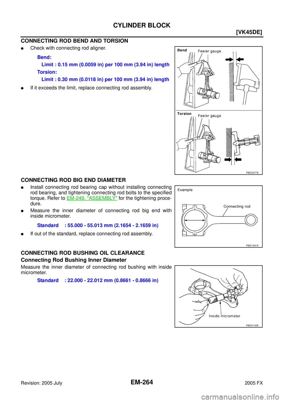
CONNECTING ROD BEND AND TORSION
�Check with connecting rod aligner.
�If it exceeds the limit, replace connecting rod assembly.
CONNECTING ROD BIG END DIAMETER
�Install connecting rod bearing cap without installing connecting
rod bearing, and tightening connecting rod bolts to the specified
torque. Refer to EM-249, "
ASSEMBLY" for the tightening proce-
dure.
�Measure the inner diameter of connecting rod big end with
inside micrometer.
�If out of the standard, replace connecting rod assembly.
CONNECTING ROD BUSHING OIL CLEARANCE
Connecting Rod Bushing Inner Diameter
Measure the inner diameter of connecting rod bushing with inside
micrometer. Bend:
Limit : 0.15 mm (0.0059 in) per 100 mm (3.94 in) length
Torsion: Limit : 0.30 mm (0.0118 in) per 100 mm (3.94 in) length
PBIC2077E
Standard : 55.000 - 55.013 mm (2.1654 - 2.1659 in)
PBIC1641E
Standard : 22.000 - 22.012 mm (0.8661 - 0.8666 in)
PBIC0120E
![INFINITI FX35 2005 Service Manual CYLINDER BLOCK EM-259
[VK45DE]
C
D E
F
G H
I
J
K L
M A
EM
Revision: 2005 July 2005 FX
Main Bearing Selection Table (No. 1 and 5 Journal)
PBIC2375E](/manual-img/42/57020/w960_57020-3093.png "INFINITI FX35 2005 Service Manual CYLINDER BLOCK EM-259
[VK45DE]
C
D E
F
G H
I
J
K L
M A
EM
Revision: 2005 July 2005 FX
Main Bearing Selection Table (No. 1 and 5 Journal)
PBIC2375E")
![INFINITI FX35 2005 Service Manual EM-260
[VK45DE]
CYLINDER BLOCK
Revision: 2005 July 2005 FX
Main Bearing Selection Table (No. 2, 3 and 4 Journal)
PBIC2376E](/manual-img/42/57020/w960_57020-3094.png "INFINITI FX35 2005 Service Manual EM-260
[VK45DE]
CYLINDER BLOCK
Revision: 2005 July 2005 FX
Main Bearing Selection Table (No. 2, 3 and 4 Journal)
PBIC2376E")