Page 3133 of 4731
FAX-8
[AWD]
PREPARATION
Revision: 2005 July 2005 FX
PREPARATIONPFP:00002
Special Service Tools (SST)ADS000OI
The actual shapes of Kent-Moore tools may differ from those of special service tools illustrated here.
Commercial Service ToolsADS000OJ
Tool number
(Kent-Moore No.)
Tool name Description
HT72520000
(J25730-A)
Ball joint remover
a: 33 mm (1.30 in)
b: 50 mm (1.97 in)
r: 11.5 mm (0.453 in)
�Removing steering outer socket
�Removing transverse link
KV381 00500
( — )
Drift
a: 80 mm (3.15 in) dia.
b: 60 mm (2.36 in) dia. Installing drive shaft plug
KV381 02200
( — )
Drift
a: 90 mm (3.54 in) dia.
b: 31 mm (1.22 in) dia. Installing drive shaft plug
NT546
ZZA0701D
ZZA0920D
Tool name Description
Power tool
�Removing wheel nuts
�Removing brake caliper assembly
�Removing hub lock nut
�Removing strut lower side
�Removing wheel hub and bearing assembly
�Removing undercoverPBIC0190E
Page 3136 of 4731
![INFINITI FX35 2005 Service Manual FRONT WHEEL HUB AND KNUCKLE FAX-11
[AWD]
C E F
G H
I
J
K L
M A
B
FA X
Revision: 2005 July 2005 FX
6. Use a ball joint remover (SST) to remove steering outer socket
from steering knuckle.](/manual-img/42/57020/w960_57020-3135.png "INFINITI FX35 2005 Service Manual FRONT WHEEL HUB AND KNUCKLE FAX-11
[AWD]
C E F
G H
I
J
K L
M A
B
FA X
Revision: 2005 July 2005 FX
6. Use a ball joint remover (SST) to remove steering outer socket
from steering knuckle.")
FRONT WHEEL HUB AND KNUCKLE FAX-11
[AWD]
C E F
G H
I
J
K L
M A
B
FA X
Revision: 2005 July 2005 FX
6. Use a ball joint remover (SST) to remove steering outer socket
from steering knuckle. Be careful not to damage ball joint boot.
CAUTION:
Tighten temporarily mounting nut to prevent damage to
threads and to prevent ball joint remover (SST) from com-
ing off.
7. Remove cotter pin at transverse link, then loosen mounting nut.
8. Use a ball joint remover (SST) to remove transverse link from steering knuckle. Be careful not to damage ball joint boot.
CAUTION:
Tighten temporarily mounting nut to prevent damage to
threads and to prevent ball joint remover (SST) from com-
ing off.
9. Remove cotter pin, then remove lock nut from drive shaft with power tool.
10. Remove steering knuckle from drive shaft. CAUTION:
�When removing steering knuckle, do not apply an exces-
sive angle to drive shaft joint. Also be careful not to excessively extend slide joint.
�Do not hang over drive shaft without support.
11. Remove fixing bolts and nuts between strut assembly and steering knuckle with power tool.
12. Remove steering knuckle from vehicle.
13. Remove fixing bolts between steering knuckle and wheel hub and bearing assembly with power tool.
14. Remove splash guard and wheel hub and bearing assembly from steering knuckle.
INSPECTION AFTER REMOVAL
Check for deformity, cracks and damage on each parts, replace if necessary.
Ball Joint Inspection
Check for boot breakage, axial looseness, and torque of transverse link and steering outer socket ball joint.
Refer to FSU-14, "
TRANSVERSE LINK" , PS-19, "POWER STEERING GEAR AND LINKAGE" .
INSTALLATION
�Refer to FAX-10, "Removal and Installation" for tightening torque. Install in the reverse order of removal.
NOTE:
Refer to component parts location and do not reuse non-reusable parts.
�After removing/installing or replacing axle components, check wheel alignment. Refer to FSU-6, "Wheel
Alignment Inspection" .
�After adjusting wheel alignment, adjust neutral position of steering angle sensor. Refer to BRC-6, "Adjust-
ment of Steering Angle Sensor Neutral Position" .
�Check the following item after service.
–Installation condition of wheel sensor harness.
SDIA1434E
SDIA1435E
Page 3137 of 4731
![INFINITI FX35 2005 Service Manual FAX-12
[AWD]
FRONT DRIVE SHAFT
Revision: 2005 July 2005 FX
FRONT DRIVE SHAFTPFP:39100
Removal and Installation (Left Side)ADS000ON
REMOVAL
1. Remove tire from vehicle with power tool.
2. Remove under](/manual-img/42/57020/w960_57020-3136.png "INFINITI FX35 2005 Service Manual FAX-12
[AWD]
FRONT DRIVE SHAFT
Revision: 2005 July 2005 FX
FRONT DRIVE SHAFTPFP:39100
Removal and Installation (Left Side)ADS000ON
REMOVAL
1. Remove tire from vehicle with power tool.
2. Remove under")
FAX-12
[AWD]
FRONT DRIVE SHAFT
Revision: 2005 July 2005 FX
FRONT DRIVE SHAFTPFP:39100
Removal and Installation (Left Side)ADS000ON
REMOVAL
1. Remove tire from vehicle with power tool.
2. Remove undercover with power tool.
3. Remove cotter pin. Then remove lock nut from drive shaft with power tool.
4. Remove wheel sensor harness from strut assembly. Refer to BRC-57, "
WHEEL SENSORS" .
CAUTION:
Do not pull on wheel sensor harness.
5. Remove brake hose lock plate. Then remove brake hose from strut assembly. Refer to BR-11, "
BRAKE
PIPING AND HOSE" .
6. Remove fixing bolts and nuts between strut assembly and steering knuckle with power tool.
7. Remove drive shaft from steering knuckle. CAUTION:
When removing drive shaft, do not apply an excessive angle to drive shaft joint. Also be careful
not to excessively extend slide joint.
8. Remove fixing bolt of front final drive side assembly drive shaft with power tool, then remove drive shaft from vehicle.
INSPECTION AFTER REMOVAL
�Move joint up/down, left /right, and in the axial direction. Check for any rough movement or significant
looseness.
�Check boot for cracks or other damage, and also for grease
leakage.
�If a trouble is found, disassemble drive shaft, and then replace
with new one.
INSTALLATION
�Refer to FA X - 1 2 , "Removal and Installation (Left Side)" for tightening torque. Install in the reverse order of
removal.
NOTE:
Refer to component parts location and do not reuse non-reusable parts.
�Check the following item after service.
–Installation condition of wheel sensor harness
1. Cotter pin 2. Washer
SDIA1441E
SDIA1046J
Page 3138 of 4731
![INFINITI FX35 2005 Service Manual FRONT DRIVE SHAFT FAX-13
[AWD]
C E F
G H
I
J
K L
M A
B
FA X
Revision: 2005 July 2005 FX
Removal and Installation (Right Side)ADS000OO
REMOVAL
1. Remove tire from vehicle with power tool.](/manual-img/42/57020/w960_57020-3137.png "INFINITI FX35 2005 Service Manual FRONT DRIVE SHAFT FAX-13
[AWD]
C E F
G H
I
J
K L
M A
B
FA X
Revision: 2005 July 2005 FX
Removal and Installation (Right Side)ADS000OO
REMOVAL
1. Remove tire from vehicle with power tool.")
FRONT DRIVE SHAFT FAX-13
[AWD]
C E F
G H
I
J
K L
M A
B
FA X
Revision: 2005 July 2005 FX
Removal and Installation (Right Side)ADS000OO
REMOVAL
1. Remove tire from vehicle with power tool.
2. Remove undercover with power tool.
3. Remove cotter pin. Then remove lock nut from drive shaft with power tool.
4. Remove wheel sensor harness from strut assembly. Refer to BRC-57, "
WHEEL SENSORS" .
CAUTION:
Do not pull on wheel sensor harness.
5. Remove brake hose lock prate. Then remove brake hose from strut assembly. Refer to BR-11, "
BRAKE
PIPING AND HOSE" .
6. Remove fixing bolts and nuts between strut assembly and steering knuckle with power tool.
7. Remove drive shaft from steering knuckle. CAUTION:
When removing drive shaft, do not apply an excessive angle to drive shaft joint. Also be careful
not to excessively extend slide joint.
8. Pry off drive shaft from front final drive assembly side as shown in the figure.
INSPECTION AFTER REMOVAL
�Move joint up/down, left/right, and in the axial direction. Check for any rough movement or significant
looseness.
�Check boot for cracks or other damage, and also for grease
leakage.
�If a trouble is found, disassemble drive shaft, and then replace
with new one.
1. Cotter pin 2. Washer
SDIA1442E
SDIA1489E
SFA108A
Page 3151 of 4731
FAX-26
[AWD]
SERVICE DATA
Revision: 2005 July 2005 FX
SERVICE DATAPFP:00030
Wheel BearingADS000OR
Drive ShaftADS000OS
Tightening TorqueADS000OT
Axial end play 0.05 mm (0.002 in) or less
Joint type (Wheel side) (Transaxle side)
Grease quantity 95 − 115 g (3.35 − 4.06 oz) 95
− 105 g (3.35 − 3.70 oz) (LH side)
11 3 − 123 g (3.99 − 4.34 oz) (RH side)
Boots installed length 136 mm (5.35 in) 95
− 97 mm (3.74 − 3.82 in) (LH side)
157.8 − 159.8 mm (6.21 − 6.29 in) (RH side)
Drive shaft - Side flange 44.5 N·m (4.5 kg-m, 33 lb)
Hub lock nut 275 N·m (28 kg-m, 203 lb)
Page 3156 of 4731
PREPARATION FFD-5
C E F
G H
I
J
K L
M A
B
FFD
Revision: 2005 July 2005 FX
Commercial Service ToolsADS00195
KV38100200
(—)
Drift
a: 65 mm (2.56 in) dia.
b: 49 mm (1.93 in) dia. Installing side shaft oil seal
(J-8129)
Spring gauge Measuring turning torque
Tool number
(Kent-Moore No.)
Tool name Description
ZZA1143D
NT127
Tool name
Description
Flange wrench Removing and installing drive pinion lock nut
Spacer
a: 60 mm (2.36 in) dia.
b: 36 mm (1.42 in) dia.
c: 30 mm (1.18 in) Installing pinion front bearing inner race
Power tool Loosening bolts and nuts
NT771
ZZA1133D
PBIC0190E
Page 3160 of 4731
FRONT OIL SEAL FFD-9
C E F
G H
I
J
K L
M A
B
FFD
Revision: 2005 July 2005 FX
FRONT OIL SEALPFP:38189
Removal and InstallationADS0019N
REMOVAL
1. Remove front propeller shaft. Refer to PR-5, "Removal and Installation" .
2. Remove drive pinion lock nut using a flange wrench.
3. Put matching mark on the end of the drive pinion. The matching mark should be in line with the matching mark A on companion
flange.
CAUTION:
For matching mark, use paint. Do not damage drive pinion.
NOTE:
The matching mark A on the final drive companion flange indi-
cates the maximum vertical runout position.
4. Remove companion flange using a puller.
5. Remove front oil seal using the puller.
PDIA0651E
PDIA0650E
PDIA0652E
Tool number : KV381054S0 (J-34286)
PDIA0653E
Page 3161 of 4731
FFD-10
FRONT OIL SEAL
Revision: 2005 July 2005 FX
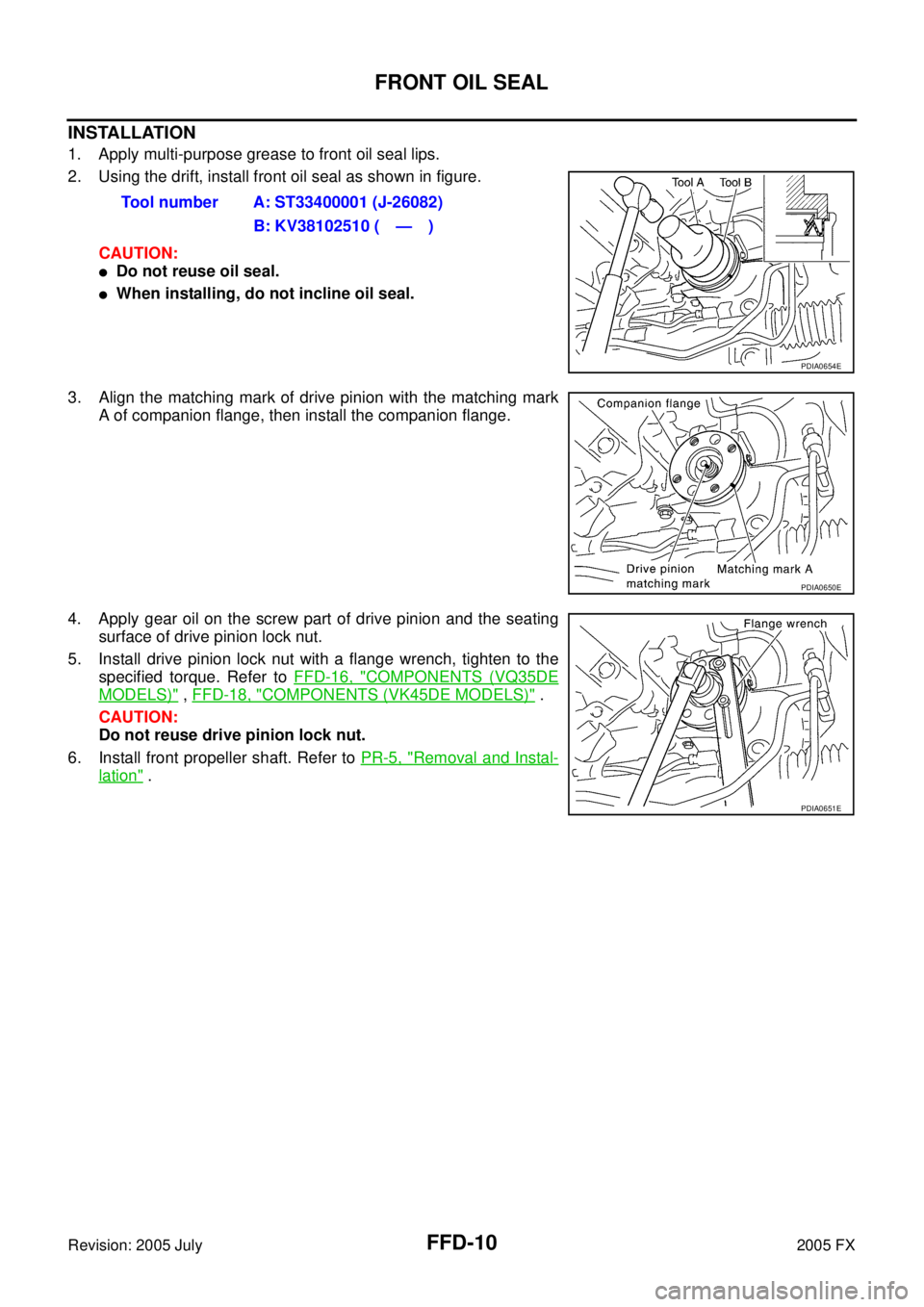
INSTALLATION
1. Apply multi-purpose grease to front oil seal lips.
2. Using the drift, install front oil seal as shown in figure.
CAUTION:
�Do not reuse oil seal.
�When installing, do not incline oil seal.
3. Align the matching mark of drive pinion with the matching mark A of companion flange, then install the companion flange.
4. Apply gear oil on the screw part of drive pinion and the seating surface of drive pinion lock nut.
5. Install drive pinion lock nut with a flange wrench, tighten to the specified torque. Refer to FFD-16, "
COMPONENTS (VQ35DE
MODELS)" , FFD-18, "COMPONENTS (VK45DE MODELS)" .
CAUTION:
Do not reuse drive pinion lock nut.
6. Install front propeller shaft. Refer to PR-5, "
Removal and Instal-
lation" .
Tool number A: ST33400001 (J-26082)
B: KV38102510 ( — )
PDIA0654E
PDIA0650E
PDIA0651E
![INFINITI FX35 2005 Service Manual FAX-8
[AWD]
PREPARATION
Revision: 2005 July 2005 FX
PREPARATIONPFP:00002
Special Service Tools (SST)ADS000OI
The actual shapes of Kent-Moore tools may differ from those of special service tools illust](/manual-img/42/57020/w960_57020-3132.png "INFINITI FX35 2005 Service Manual FAX-8
[AWD]
PREPARATION
Revision: 2005 July 2005 FX
PREPARATIONPFP:00002
Special Service Tools (SST)ADS000OI
The actual shapes of Kent-Moore tools may differ from those of special service tools illust")
![INFINITI FX35 2005 Service Manual FAX-26
[AWD]
SERVICE DATA
Revision: 2005 July 2005 FX
SERVICE DATAPFP:00030
Wheel BearingADS000OR
Drive ShaftADS000OS
Tightening TorqueADS000OT
Axial end play 0.05 mm (0.002 in) or less
Joint type (Wh](/manual-img/42/57020/w960_57020-3150.png "INFINITI FX35 2005 Service Manual FAX-26
[AWD]
SERVICE DATA
Revision: 2005 July 2005 FX
SERVICE DATAPFP:00030
Wheel BearingADS000OR
Drive ShaftADS000OS
Tightening TorqueADS000OT
Axial end play 0.05 mm (0.002 in) or less
Joint type (Wh")

Drift
a: 65 mm (2.56 in) dia.
b: 49 mm (1.93 in) dia. Instal")