Page 2729 of 4731
EC-1336
[VK45DE]
VARIABLE INDUCTION AIR CONTROL SYSTEM (VIAS)
Revision: 2005 July 2005 FX
4. CHECK VACUUM HOSE
1. Stop engine.
2. Check hoses and tubes between intake manifold and power valve actuator for crack, clogging, improper connection or dis-
connection. Refer to EC-810, "
Vacuum Hose Drawing" .
OK or NG
OK >> GO TO 5.
NG >> Repair hoses or tubes.
5. CHECK VACUUM TANK
Refer to EC-1337, "
Component Inspection" .
OK or NG
OK >> GO TO 6.
NG >> Replace vacuum tank.
6. CHECK VIAS CONTROL SOLENOID VALVE POWER SUPPLY CIRCUIT
1. Turn ignition switch OFF.
2. Disconnect VIAS control solenoid valve harness connector.
3. Turn ignition switch ON.
4. Check voltage between terminal 1 and ground with CONSULT-II or tester.
OK or NG
OK >> GO TO 8.
NG >> GO TO 7.
SEF109L
PBIB1498E
Voltage: Battery voltage
PBIB0173E
Page 2734 of 4731
IGNITION SIGNAL EC-1341
[VK45DE]
C
D E
F
G H
I
J
K L
M A
EC
Revision: 2005 July 2005 FX
Specification data are reference values and are measured between each terminal and ground.
CAUTION:
Do not use ECM ground terminals when measuring input/output voltage. Doing so may result in dam-
age to the ECM's transistor. Use a ground other than ECM terminals, such as the ground.
TER-
MINAL NO. WIRE
COLOR ITEM CONDITION DATA (DC Voltage)
111 W / B ECM relay
(Self shut-off) [Engine is running]
[Ignition switch: OFF]
�For a few seconds after turning ignition
switch OFF 0 - 1.5V
[Ignition switch: OFF]
�More than a few seconds after turning igni-
tion switch OFF BATTERY VOLTAGE
(11 - 14V)
11 9
120 R
R Power supply for ECM
[Ignition switch: ON] BATTERY VOLTAGE
(11 - 14V)
Page 2739 of 4731
EC-1346
[VK45DE]
IGNITION SIGNAL
Revision: 2005 July 2005 FX
3. CHECK OVERALL FUNCTION
Without CONSULT-II
1. Let engine idle.
2. Read the voltage signal between ECM terminals 46, 60, 61, 62, 65, 79, 80, 81 and ground with an oscilloscope.
3. Verify that the oscilloscope screen shows the signal wave as shown below.
NOTE:
The pulse cycle changes depending on rpm at idle.
OK or NG
OK >> INSPECTION END
NG >> GO TO 10.
4. CHECK IGNITION COIL POWER SUPPLY CIRCUIT-I
1. Turn ignition switch OFF, wait at least 10 seconds and then turn ON.
2. Check voltage between ECM terminals 119, 120 and ground with CONSULT-II or tester.
OK or NG
OK >> GO TO 5.
NG >> Go to EC-855, "
POWER SUPPLY AND GROUND CIR-
CUIT" .
PBIB1549E
PBIB0044E
Voltage: Battery voltage
MBIB0034E
Page 2740 of 4731
![INFINITI FX35 2005 Service Manual IGNITION SIGNAL EC-1347
[VK45DE]
C
D E
F
G H
I
J
K L
M A
EC
Revision: 2005 July 2005 FX
5. CHECK IGNITION COIL POWER SUPPLY CIRCUIT-II
1. Turn ignition switch OFF.
2. Disconnect condens](/manual-img/42/57020/w960_57020-2739.png "INFINITI FX35 2005 Service Manual IGNITION SIGNAL EC-1347
[VK45DE]
C
D E
F
G H
I
J
K L
M A
EC
Revision: 2005 July 2005 FX
5. CHECK IGNITION COIL POWER SUPPLY CIRCUIT-II
1. Turn ignition switch OFF.
2. Disconnect condens")
IGNITION SIGNAL EC-1347
[VK45DE]
C
D E
F
G H
I
J
K L
M A
EC
Revision: 2005 July 2005 FX
5. CHECK IGNITION COIL POWER SUPPLY CIRCUIT-II
1. Turn ignition switch OFF.
2. Disconnect condenser harness connector.
3. Turn ignition switch ON.
4. Check voltage between condenser terminal 1 and ground with CONSULT-II or tester.
OK or NG
OK >> GO TO 8.
NG >> GO TO 6.
6. CHECK IGNITION COIL POWER SUPPLY CIRCUIT-III
1. Turn ignition switch OFF.
2. Disconnect IPDM E/R harness connector E7.
3. Check harness continuity between IPDM E/R terminal 17 and condenser terminal 1. Refer to Wiring Diagram.
4. Also check harness for short to ground and short to power.
OK or NG
OK >> Go to EC-855, "POWER SUPPLY AND GROUND CIRCUIT" .
NG >> GO TO 7.
7. DETECT MALFUNCTIONING PART
Check the following.
�Harness connectors E19, F49
�Harness for open or short between IPDM E/R and condenser
>> Repair open circuit or short to ground or short to power in harness or connectors.
PBIB1532E
Voltage: Battery voltage
PBIB0624E
Continuity should exist.
Page 2741 of 4731
![INFINITI FX35 2005 Service Manual EC-1348
[VK45DE]
IGNITION SIGNAL
Revision: 2005 July 2005 FX
8. CHECK CONDENSER GROUND CIRCUIT FOR OPEN AND SHORT
1. Turn ignition switch OFF.
2. Check harness continuity between condenser terminal](/manual-img/42/57020/w960_57020-2740.png "INFINITI FX35 2005 Service Manual EC-1348
[VK45DE]
IGNITION SIGNAL
Revision: 2005 July 2005 FX
8. CHECK CONDENSER GROUND CIRCUIT FOR OPEN AND SHORT
1. Turn ignition switch OFF.
2. Check harness continuity between condenser terminal")
EC-1348
[VK45DE]
IGNITION SIGNAL
Revision: 2005 July 2005 FX
8. CHECK CONDENSER GROUND CIRCUIT FOR OPEN AND SHORT
1. Turn ignition switch OFF.
2. Check harness continuity between condenser terminal 2 and ground. Refer to Wiring Diagram.
3. Also check harness for short to power.
OK or NG
OK >> GO TO 9.
NG >> Repair open circuit or short to power in harness or connectors.
9. CHECK CONDENSER
Refer to EC-1349, "
Component Inspection"
OK or NG
OK >> GO TO 10.
NG >> Replace condenser.
10. CHECK IGNITION COIL POWER SUPPLY CIRCUIT-V
1. Reconnect all harness connectors disconnected.
2. Disconnect ignition coil harness connector.
3. Turn ignition switch ON.
4. Check voltage between ignition coil terminal 3 and ground with CONSULT-II or tester.
OK or NG
OK >> GO TO 12.
NG >> GO TO 11.
11 . DETECT MALFUNCTIONING PART
Check the following.
�Harness connector F49
�Harness for open or short between ignition coil and harness connector F49
>> Repair or replace harness or connectors.
Continuity should exist.
Voltage: Battery voltage
PBIB1516E
PBIB0138E
Page 2746 of 4731
![INFINITI FX35 2005 Service Manual INJECTOR CIRCUIT EC-1353
[VK45DE]
C
D E
F
G H
I
J
K L
M A
EC
Revision: 2005 July 2005 FX
Specification data are reference values and are measured between each terminal and ground.
Pulse](/manual-img/42/57020/w960_57020-2745.png "INFINITI FX35 2005 Service Manual INJECTOR CIRCUIT EC-1353
[VK45DE]
C
D E
F
G H
I
J
K L
M A
EC
Revision: 2005 July 2005 FX
Specification data are reference values and are measured between each terminal and ground.
Pulse")
INJECTOR CIRCUIT EC-1353
[VK45DE]
C
D E
F
G H
I
J
K L
M A
EC
Revision: 2005 July 2005 FX
Specification data are reference values and are measured between each terminal and ground.
Pulse signal is measured by CONSULT-II.
CAUTION:
Do not use ECM ground terminals when measuring input/output voltage. Doing so may result in dam-
age to the ECM's transistor. Use a ground other than ECM terminals, such as the ground.
: Average voltage for pulse signal (Actual pulse signal can be confirmed by oscilloscope.)
Diagnostic ProcedureABS00E5T
1. INSPECTION START
Turn ignition switch to START.
Is any cylinder ignited?
Ye s o r N o
Yes (With CONSULT-II)>>GO TO 2.
Yes (Without CONSULT-II)>>GO TO 3.
No >> GO TO 3.
2. CHECK OVERALL FUNCTION
With CONSULT-II
1. Start engine.
2. Perform “POWER BALANCE” in “ACTIVE TEST” mode with CONSULT-II.
3. Make sure that each circuit produces a momentary engine speed drop.
OK or NG
OK >> INSPECTION END
NG >> GO TO 3.
TER-
MINAL
NO. WIRE
COLOR ITEM CONDITION DATA (DC Voltage)
21
22
23
40
41
42
44
63 W
R
P
PU
BR
B
OR
G Injector No. 5
Injector No. 3
Injector No. 1
Injector No. 6
Injector No. 4
Injector No. 2
Injector No. 7
Injector No. 8 [Engine is running]
�Warm-up condition
�Idle speed
NOTE:
The pulse cycle changes depending on rpm
at idle BATTERY VOLTAGE
(11 - 14V)
[Engine is running]
�Warm-up condition
�Engine speed: 2,000 rpm BATTERY VOLTAGE
(11 - 14V)
PBIB0042E
PBIB0043E
PBIB0133E
Page 2747 of 4731
EC-1354
[VK45DE]
INJECTOR CIRCUIT
Revision: 2005 July 2005 FX
3. CHECK FUNCTION OF INJECTOR-I
1. Turn ignition switch OFF.
2. Disconnect harness connector F21, F201 (bank 1) and F41, F221 (bank 2).
3. Turn ignition switch ON.
4. Check voltage between the following; harness connector F21 terminal 5 and ground,
harness connector F41 terminal 5 and ground
with CONSULT-II or tester.
5. Turn ignition switch OFF.
6. Disconnect ECM harness connector.
7. Check harness continuity between the following terminals.
8. Also check harness for short to ground and short to power.
OK or NG
OK >> GO TO 5.
NG >> GO TO 4. Voltage: Battery voltage
Cylinder Harness connector terminal ECM terminal
1 F21 terminal 3 23
3 F21 terminal 2 22
5 F21 terminal 1 21
7 F21 terminal 6 44
2 F41 terminal 3 42
4 F41 terminal 2 41
6 F41 terminal 1 40
8 F41 terminal 6 63
Continuity should exist.
PBIB2561E
PBIB0180E
Page 2748 of 4731
INJECTOR CIRCUIT EC-1355
[VK45DE]
C
D E
F
G H
I
J
K L
M A
EC
Revision: 2005 July 2005 FX
4. DETECT MALFUNCTIONING PART
Check the following.
�Harness connectors M82, F102
�Harness connectors F21, F201
�Harness connectors F41, F221
�Fuse block (J/B) connector M1
�15A fuse
�Harness for open or short between harness connector F21 and fuse
�Harness for open or short between harness connector F41 and fuse
�Harness for open or short between harness connector F21 and ECM
�Harness for open or short between harness connector F41 and ECM
>> Repair open circuit or short to ground or short to power in harness or connectors.
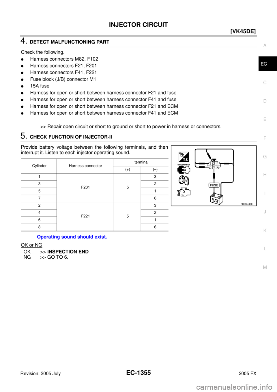
5. CHECK FUNCTION OF INJECTOR-II
Provide battery voltage between the following terminals, and then
interrupt it. Listen to each injector operating sound.
OK or NG
OK >> INSPECTION END
NG >> GO TO 6.
Cylinder Harness connector terminal
(+) (–)
1
F201 5 3
32
51
76
2
F221 5 3
42
61
86
Operating sound should exist.
PBIB2449E
![INFINITI FX35 2005 Service Manual EC-1336
[VK45DE]
VARIABLE INDUCTION AIR CONTROL SYSTEM (VIAS)
Revision: 2005 July 2005 FX
4. CHECK VACUUM HOSE
1. Stop engine.
2. Check hoses and tubes between intake manifold and power valve actua](/manual-img/42/57020/w960_57020-2728.png "INFINITI FX35 2005 Service Manual EC-1336
[VK45DE]
VARIABLE INDUCTION AIR CONTROL SYSTEM (VIAS)
Revision: 2005 July 2005 FX
4. CHECK VACUUM HOSE
1. Stop engine.
2. Check hoses and tubes between intake manifold and power valve actua")
![INFINITI FX35 2005 Service Manual IGNITION SIGNAL EC-1341
[VK45DE]
C
D E
F
G H
I
J
K L
M A
EC
Revision: 2005 July 2005 FX
Specification data are reference values and are measured between each terminal and ground.
CAUTION](/manual-img/42/57020/w960_57020-2733.png "INFINITI FX35 2005 Service Manual IGNITION SIGNAL EC-1341
[VK45DE]
C
D E
F
G H
I
J
K L
M A
EC
Revision: 2005 July 2005 FX
Specification data are reference values and are measured between each terminal and ground.
CAUTION")
![INFINITI FX35 2005 Service Manual EC-1346
[VK45DE]
IGNITION SIGNAL
Revision: 2005 July 2005 FX
3. CHECK OVERALL FUNCTION
Without CONSULT-II
1. Let engine idle.
2. Read the voltage signal between ECM terminals 46, 60, 61, 62, 65, 7](/manual-img/42/57020/w960_57020-2738.png "INFINITI FX35 2005 Service Manual EC-1346
[VK45DE]
IGNITION SIGNAL
Revision: 2005 July 2005 FX
3. CHECK OVERALL FUNCTION
Without CONSULT-II
1. Let engine idle.
2. Read the voltage signal between ECM terminals 46, 60, 61, 62, 65, 7")
![INFINITI FX35 2005 Service Manual EC-1354
[VK45DE]
INJECTOR CIRCUIT
Revision: 2005 July 2005 FX
3. CHECK FUNCTION OF INJECTOR-I
1. Turn ignition switch OFF.
2. Disconnect harness connector F21, F201 (bank 1) and F41, F221 (bank 2).](/manual-img/42/57020/w960_57020-2746.png "INFINITI FX35 2005 Service Manual EC-1354
[VK45DE]
INJECTOR CIRCUIT
Revision: 2005 July 2005 FX
3. CHECK FUNCTION OF INJECTOR-I
1. Turn ignition switch OFF.
2. Disconnect harness connector F21, F201 (bank 1) and F41, F221 (bank 2).")