Page 3148 of 4731
![INFINITI FX35 2005 Service Manual FRONT DRIVE SHAFT FAX-23
[AWD]
C E F
G H
I
J
K L
M A
B
FA X
Revision: 2005 July 2005 FX
7. Install boot securely into grooves (indicated by * marks) shown
in the figure.
CAUTION:
If the INFINITI FX35 2005 Service Manual FRONT DRIVE SHAFT FAX-23
[AWD]
C E F
G H
I
J
K L
M A
B
FA X
Revision: 2005 July 2005 FX
7. Install boot securely into grooves (indicated by * marks) shown
in the figure.
CAUTION:
If the](/manual-img/42/57020/w960_57020-3147.png)
FRONT DRIVE SHAFT FAX-23
[AWD]
C E F
G H
I
J
K L
M A
B
FA X
Revision: 2005 July 2005 FX
7. Install boot securely into grooves (indicated by * marks) shown
in the figure.
CAUTION:
If there is grease on boot mounting surfaces (indicated by*
marks) of shaft and housing, boot may come off. Remove
all grease from surfaces.
8. Make sure boot installation length “L” is the length indicated below. Insert a flat-bladed screwdriver or similar tool into smaller
side of boot. Bleed air from boot to prevent boot deformation.
CAUTION:
�Boot may break if boot installation length is less than standard value.
�Take care not to touch the tip of screwdriver to inside surface of boot.
9. Install new larger and smaller boot bands securely.
a. For one-touch clamp band: NOTE:
�Discard old boot bands; replace with new ones with a suitable
tool.
�Secure boot band so that dimension “M” shown bellow right
satisfies the following:
b. For low profile type band:
i. Set boot band in the specified grooves. Fit band's pawl to the grooves and tack them. Boot installation Length “L ”:
157.8 − 159.8 mm (6.21 − 6.29 in)
SDIA1737E
RAC1133D
Large diameter side : 3.0 mm (0.118 in)
Small diameter side : 2.0 mm (0.079 in)
DSF0047D
SDIA3053J
Page 3150 of 4731
![INFINITI FX35 2005 Service Manual FRONT DRIVE SHAFT FAX-25
[AWD]
C E F
G H
I
J
K L
M A
B
FA X
Revision: 2005 July 2005 FX
4. Attach circular clip to shaft. At this time, circular clip must fit
securely into shaft groove. INFINITI FX35 2005 Service Manual FRONT DRIVE SHAFT FAX-25
[AWD]
C E F
G H
I
J
K L
M A
B
FA X
Revision: 2005 July 2005 FX
4. Attach circular clip to shaft. At this time, circular clip must fit
securely into shaft groove.](/manual-img/42/57020/w960_57020-3149.png)
FRONT DRIVE SHAFT FAX-25
[AWD]
C E F
G H
I
J
K L
M A
B
FA X
Revision: 2005 July 2005 FX
4. Attach circular clip to shaft. At this time, circular clip must fit
securely into shaft groove. Attach nut to joint sub-assembly.
Use a wooden hammer to press-fit.
NOTE:
Discard old circular clip; replace with new one.
5. Insert the specified amount of grease (Nissan genuine grease or equivalent) listed below into boot from large end of boot.
6. Install boot securely into grooves (indicated by * marks) shown in the figure.
CAUTION:
If there is grease on boot mounting surfaces (indicated by*
marks) of shaft and housing of joint sub-assembly, boot
may come off. Remove all grease from surfaces.
7. Make sure boot installation length “L” is the length indicated below. Insert a flat-bladed screwdriver or similar tool into smaller
side of boot. Bleed air from boot to prevent boot deformation.
CAUTION:
�Boot may brake if boot installation length is less than standard value.
�Be careful that screwdriver tip does not contact inside surface of boot.
8. Install new larger and smaller boot bands securely with a suit- able tool.
NOTE:
�Discard old boot band; replace with new ones.
�Secure boot band so that dimension “M” shown bellow right
satisfies the following:
9. After installing joint sub-assembly and shaft, rotate boot to check whether or not the actual position is correct. If boot position is
not correct, secure boot with new boot bands again. Grease amount : 95
− 11 5 g ( 3 . 3 5 − 4.06 oz)
RAC0049D
Boot installation length “L” : 136 mm (5.35 in) SDIA1736E
RAC1133D
Large diameter side : 3.0 mm (0.118 in)
Small diameter side : 2.0 mm (0.079 in)
DSF0047D
Page 3151 of 4731
FAX-26
[AWD]
SERVICE DATA
Revision: 2005 July 2005 FX
SERVICE DATAPFP:00030
Wheel BearingADS000OR
Drive ShaftADS000OS
Tightening TorqueADS000OT
Axial end play 0.05 mm (0.002 in) or less
Joint type (Wheel side) (Transaxle side)
Grease quantity 95 − 115 g (3.35 − 4.06 oz) 95
− 105 g (3.35 − 3.70 oz) (LH side)
11 3 − 123 g (3.99 − 4.34 oz) (RH side)
Boots installed length 136 mm (5.35 in) 95
− 97 mm (3.74 − 3.82 in) (LH side)
157.8 − 159.8 mm (6.21 − 6.29 in) (RH side)
Drive shaft - Side flange 44.5 N·m (4.5 kg-m, 33 lb)
Hub lock nut 275 N·m (28 kg-m, 203 lb)
Page 3202 of 4731

FUEL TANK FL-11
C
D E
F
G H
I
J
K L
M A
FL
Revision: 2005 July 2005 FX
9. Disconnect fuel filler hose, vent hose and EVAP hoses at fuel
tank side.
10. Support the lower part of fuel tank with transmission jack. CAUTION:
Support the position that fuel tank mounting bands do not
engage.
11. Remove fuel tank mounting bands.
12. Supporting with hands, descend transmission jack carefully, and remove fuel tank. CAUTION:
�Make sure that all connection points have been disconnected.
�Confirm there is no interference with vehicle.
13. Remove fuel filler tube protector and fuel filler tube, if necessary.
INSTALLATION
Note the following, and install in the reverse order of removal.
�Surely clamp fuel hoses and insert hose to the length below.
�Be sure hose clamp is not placed on swelled area of fuel tube.
�Tighten fuel hose clamp so that the distance between its lugs becomes to the following.
�To connect quick connector, refer to FL-7, "Quick Connector" .
INSPECTION AFTER INSTALLATION
Use the following procedure to check for fuel leaks.
1. Turn ignition switch “ON” (with engine stopped), and check connections for leakage by applying fuel pres- sure to fuel piping.
2. Start engine and rev it up and make sure there are no fuel leaks at the fuel system tube and hose connec- tions.
�After removing/installing rear suspension assembly, make sure to adjust wheel alignment and then, adjust
neutral position of steering angle sensor. Refer to RSU-5, "
Wheel Alignment Inspection" and BRC-6,
"Adjustment of Steering Angle Sensor Neutral Position" .
PBIC1581E
PBIC0878E
Fuel filler hose : 35 mm (1.38 in)
The other hoses : 25 mm (0.98 in)
Fuel tank side : 8 - 12 mm (0.31 - 0.47 in)
Fuel filler tube side : 5.7 - 9.7 mm (0.224 - 0.382 in)
Page 3228 of 4731

PRECAUTIONS GI-7
C
D E
F
G H
I
J
K L
M B
GI
Revision: 2005 July 2005 FX
Precautions for Fuel (Unleaded Premium Gasoline Required)AAS000GS
Use unleaded premium gasoline with an octane rating of at least 91 AKI (Anti-Knock Index) number (Research
octane number 96).
If unleaded premium gasoline is not available, unleaded regular gasoline with an octane rating of at least 87
AKI number (Research octane number 91) can be used, but only under the following precautions:
�have the fuel tank filled only partially with unleaded regular gasoline, and fill up with unleaded premium
gasoline as soon as possible.
�avoid full throttle driving and abrupt acceleration.
However, for maximum vehicle performance, the use of unleaded premium gasoline is recommended.
CAUTION:
Do not use leaded gasoline. Using leaded gasoline will damage the three way catalyst. Using a fuel
other than that specified could adversely affect the emission control devices and systems, and could
also affect the warranty coverage validity.
Precautions for Multiport Fuel Injection System or Engine Control SystemAAS000F1
�Before connecting or disconnecting any harness connector for
the multiport fuel injection system or ECM:
Turn ignition switch to “OFF” position.
Disconnect negative battery terminal.
Otherwise, there may be damage to ECM.
�Before disconnecting pressurized fuel line from fuel pump to
injectors, be sure to release fuel pressure.
�Be careful not to jar components such as ECM and mass air
flow sensor.
Precautions for HosesAAS000F2
HOSE REMOVAL AND INSTALLATION
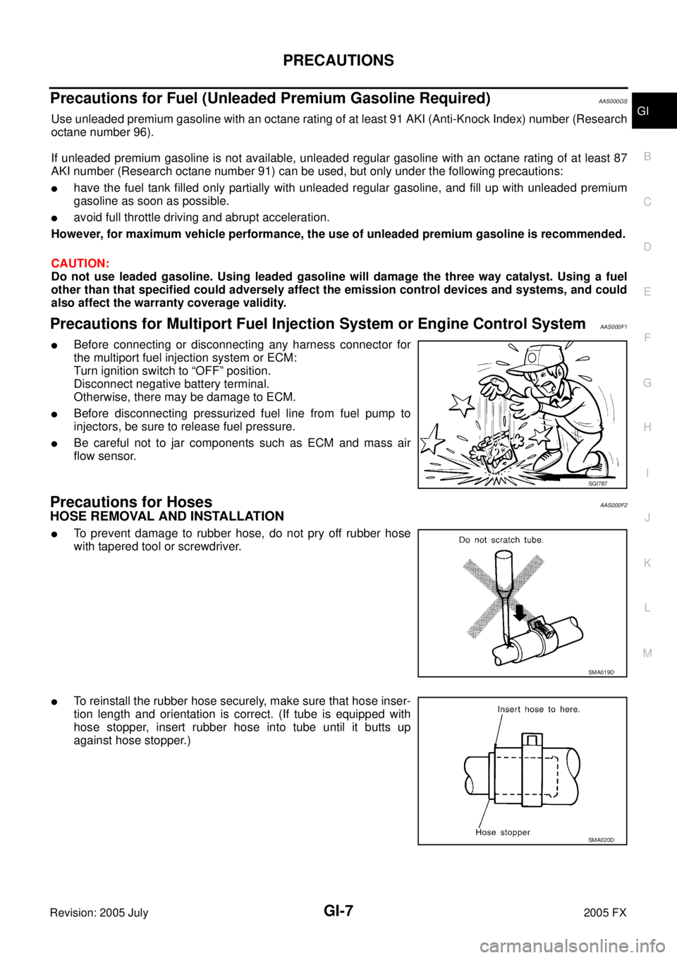
�To prevent damage to rubber hose, do not pry off rubber hose
with tapered tool or screwdriver.
�To reinstall the rubber hose securely, make sure that hose inser-
tion length and orientation is correct. (If tube is equipped with
hose stopper, insert rubber hose into tube until it butts up
against hose stopper.)
SGI787
SMA019D
SMA020D
Page 3272 of 4731
IDENTIFICATION INFORMATION GI-51
C
D E
F
G H
I
J
K L
M B
GI
Revision: 2005 July 2005 FX
ENGINE SERIAL NUMBER
AUTOMATIC TRANSMISSION NUMBER
Dimensions AAS000EM
Unit: mm (in)
Wheels & Tires AAS000EN
PAIA0110E
PA I A 0 111 E
PAIA0054E
Overall length 4,803 (189.1)
Overall width 1,925 (75.8)
Overall height without roof rack rail 1,652 (65.0)
with roof rack rail 1,672.6 (65.9)
Front tread 1,592 (62.7)
Rear tread 1,642 (64.6)
Wheelbase 2,850 (112.2)
Conventional Spare
Road wheel/offset mm (in) 18 X 8JJ Aluminum/40 (1.57)
20 X 8JJ Aluminum/40 (1.57) T175/90D18
Tire size P265/60R18
P265/50R20
Page 4275 of 4731

PR-14
SERVICE DATA AND SPECIFICATIONS (SDS)
Revision: 2005 July 2005 FX
SERVICE DATA AND SPECIFICATIONS (SDS)PFP:00030
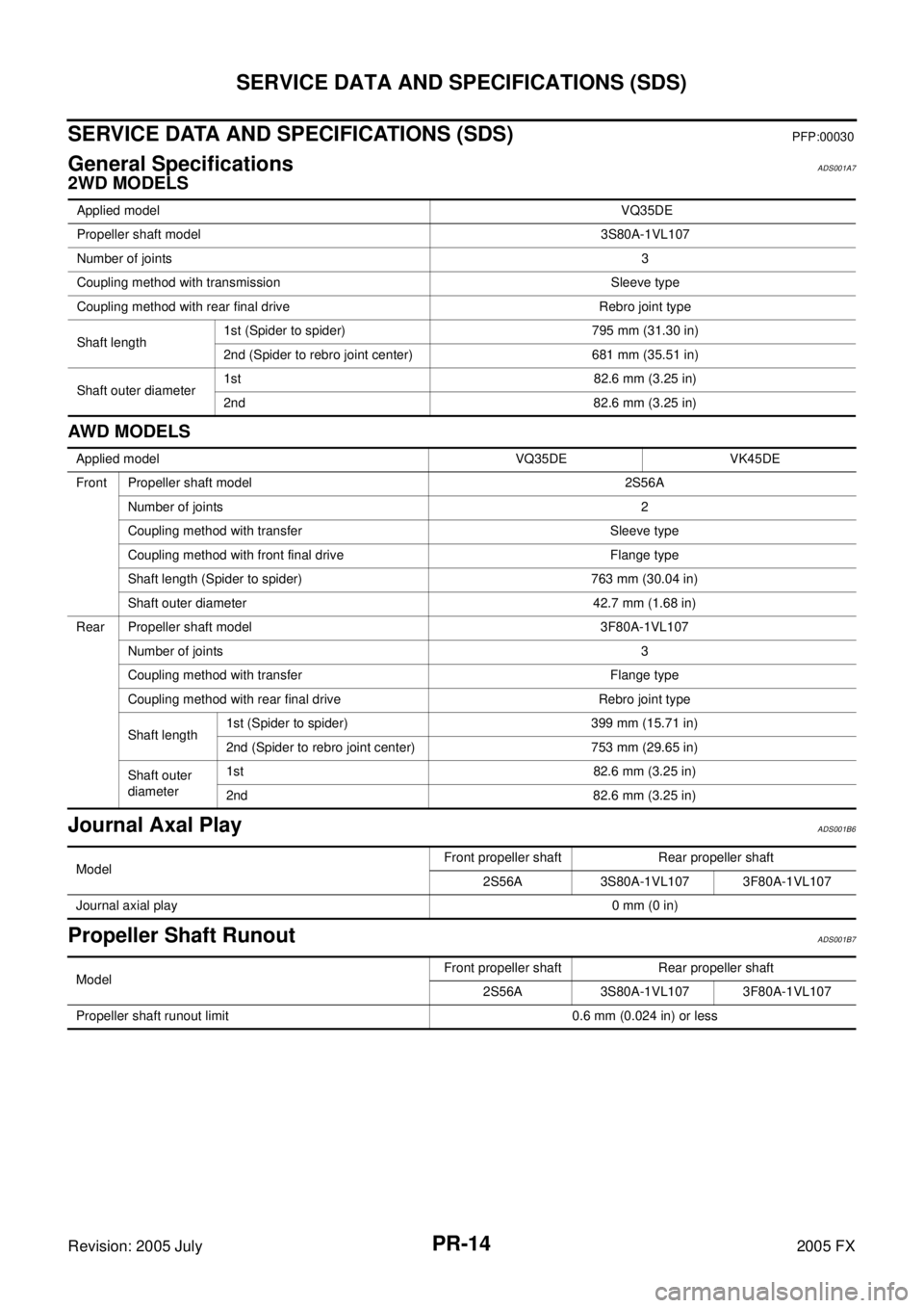
General SpecificationsADS001A7
2WD MODELS
AW D M OD E LS
Journal Axal PlayADS001B6
Propeller Shaft RunoutADS001B7
Applied model VQ35DE
Propeller shaft model 3S80A-1VL107
Number of joints 3
Coupling method with transmission Sleeve type
Coupling method with rear final drive Rebro joint type
Shaft length 1st (Spider to spider) 795 mm (31.30 in)
2nd (Spider to rebro joint center) 681 mm (35.51 in)
Shaft outer diameter 1st 82.6 mm (3.25 in)
2nd 82.6 mm (3.25 in)
Applied model VQ35DE VK45DE
Front Propeller shaft model 2S56A Number of joints 2
Coupling method with transfer Sleeve type
Coupling method with front final drive Flange type
Shaft length (Spider to spider) 763 mm (30.04 in)
Shaft outer diameter 42.7 mm (1.68 in)
Rear Propeller shaft model 3F80A-1VL107 Number of joints 3
Coupling method with transfer Flange type
Coupling method with rear final drive Rebro joint type
Shaft length 1st (Spider to spider) 399 mm (15.71 in)
2nd (Spider to rebro joint center) 753 mm (29.65 in)
Shaft outer
diameter 1st 82.6 mm (3.25 in)
2nd 82.6 mm (3.25 in)
Model Front propeller shaft Rear propeller shaft
2S56A 3S80A-1VL107 3F80A-1VL107
Journal axial play 0 mm (0 in)
Model Front propeller shaft Rear propeller shaft
2S56A 3S80A-1VL107 3F80A-1VL107
Propeller shaft runout limit 0.6 mm (0.024 in) or less
Page 4289 of 4731

PS-14
STEERING COLUMN
Revision: 2005 July 2005 FX
INSPECTION AFTER REMOVAL
�Check if there is something wrong with jacket tube of steering column assembly and collar etc. And then if
they are damaged, replace with new one.
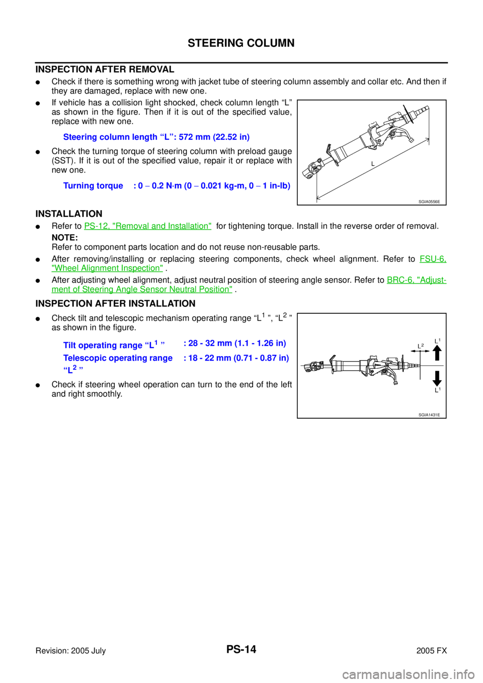
�If vehicle has a collision light shocked, check column length “L”
as shown in the figure. Then if it is out of the specified value,
replace with new one.
�Check the turning torque of steering column with preload gauge
(SST). If it is out of the specified value, repair it or replace with
new one.
INSTALLATION
�Refer to PS-12, "Removal and Installation" for tightening torque. Install in the reverse order of removal.
NOTE:
Refer to component parts location and do not reuse non-reusable parts.
�After removing/installing or replacing steering components, check wheel alignment. Refer to FSU-6,
"Wheel Alignment Inspection" .
�After adjusting wheel alignment, adjust neutral position of steering angle sensor. Refer to BRC-6, "Adjust-
ment of Steering Angle Sensor Neutral Position" .
INSPECTION AFTER INSTALLATION
�Check tilt and telescopic mechanism operating range “L1 ”, “L2 ”
as shown in the figure.
�Check if steering wheel operation can turn to the end of the left
and right smoothly. Steering column length “L”: 572 mm (22.52 in)
Turning torque : 0 − 0.2 N·m (0 − 0.021 kg-m, 0 − 1 in-lb)
SGIA0556E
Tilt operating range “L1 ” : 28 - 32 mm (1.1 - 1.26 in)
Telescopic operating range
“L
2 ” : 18 - 22 mm (0.71 - 0.87 in)
SGIA1431E