Page 4294 of 4731

POWER STEERING GEAR AND LINKAGE PS-19
C
D E
F
H I
J
K L
M A
B
PS
Revision: 2005 July 2005 FX
POWER STEERING GEAR AND LINKAGEPFP:49001
Removal and InstallationAGS000H0
CAUTION:
Spiral cable may snap due to steering operation if steering column is separated from steering gear
assembly. Therefore fix steering wheel with a string to avoid turns.
REMOVAL
1. Set wheels in the straight-ahead position.
2. Remove tires from vehicle with power tool.
3. Remove undercover with power tool.
4. Confirm slit of lower joint fits with the projection on rear cover cap, furthermore marking position on steering gear assembly
nearly fits with the projection on rear cover cap.
5. Remove cotter pin at steering outer socket, then loosen mount- ing nut.
6. Use a ball joint remover (SST) to remove steering outer socket from steering knuckle. Be careful not to damage ball joint boot.
CAUTION:
Tighten temporarily mounting nut to prevent damage to
threads and to prevent ball joint remover (SST) from com-
ing off.
1. Cotter pin 2. Steering gear assembly 3. Washer
4. Clip
SGIA1432E
SGIA0539E
SDIA1434E
Page 4295 of 4731
PS-20
POWER STEERING GEAR AND LINKAGE
Revision: 2005 July 2005 FX
7. Remove oil pipings (high pressure side and low pressure side)
from steering gear assembly, then drain fluid from pipings.
8. Remove mounting bolt of steering hydraulic piping bracket from steering gear assembly.
9. Remove mounting bolt (lower side) of lower joint.
10. Remove mounting bolts of steering gear assembly with power tool, and then remove steering gear assembly from vehicle.
INSTALLATION
�Refer to PS-19, "Removal and Installation" for tightening torque. Install in the reverse order of removal.
NOTE:
Refer to component parts location and do not reuse non-reusable parts.
�After removing/installing or replacing steering components, check wheel alignment. Refer to FSU-6,
"Wheel Alignment Inspection" .
�After adjusting wheel alignment, adjust neutral position of steering angle sensor. Refer to BRC-6, "Adjust-
ment of Steering Angle Sensor Neutral Position" .
SGIA0541E
SGIA0545E
SGIA0542E
SGIA0546E
Page 4296 of 4731
POWER STEERING GEAR AND LINKAGE PS-21
C
D E
F
H I
J
K L
M A
B
PS
Revision: 2005 July 2005 FX
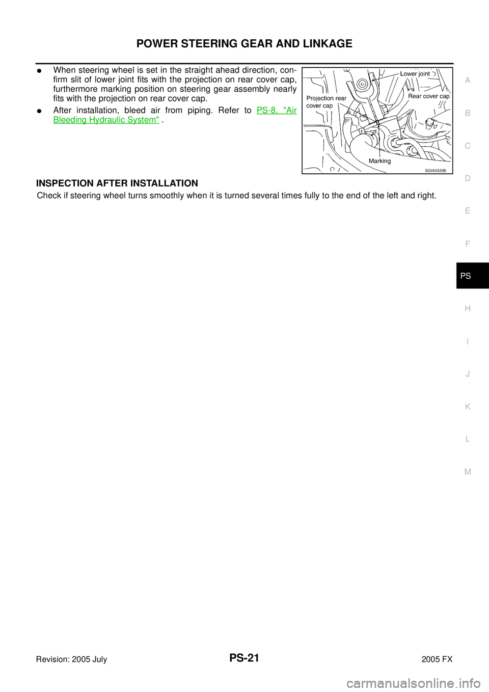
�When steering wheel is set in the straight ahead direction, con-
firm slit of lower joint fits with the projection on rear cover cap,
furthermore marking position on steering gear assembly nearly
fits with the projection on rear cover cap.
�After installation, bleed air from piping. Refer to PS-8, "Air
Bleeding Hydraulic System" .
INSPECTION AFTER INSTALLATION
Check if steering wheel turns smoothly when it is turned several times fully to the end of the left and right.
SGIA0539E
Page 4297 of 4731
PS-22
POWER STEERING GEAR AND LINKAGE
Revision: 2005 July 2005 FX
Disassembly and AssemblyAGS000H1
SGIA1433E
Page 4298 of 4731

POWER STEERING GEAR AND LINKAGE PS-23
C
D E
F
H I
J
K L
M A
B
PS
Revision: 2005 July 2005 FX
CAUTION:
�Secure steering gear assembly with a vise, using copper
plates or something similar to prevent it from being dam-
aged. Do not grip cylinder with a vise.
�Before performing disassembly, clean steering gear assem-
bly with kerosene. Be careful not to bring any kerosene into
contact with the discharge and return port connectors.
DISASSEMBLY
1. Remove cylinder tubes from gear housing assembly.
2. Remove rear cover cap from gear housing assembly.
3. Measure adjusting screw height from gear housing assembly, then loosen adjusting screw.
CAUTION:
�Do not turn adjusting screw more than twice.
�Replace steering gear assembly when adjusting screw is
removed or more than twice.
4. Use a rear cover wrench (SST) to remove rear cover from sub- gear assembly.
5. Remove O-ring with a flat-bladed screwdriver, and pull out rear cover.
6. Remove sub-gear assembly from gear housing assembly. CAUTION:
In order to protect oil seal from any damage, pull sub-gear
assembly out straightly.
7. Loosen lock nut of outer socket, and remove outer socket.
8. Remove boot clamps of the small diameter side and the large diameter side, then remove boot.
1. Cotter pin 2. Outer socket 3. Boot clamp
4. Boot 5. Inner socket 6. Boot clamp
7. Gear housing assembly 8. Cylinder tubes 9. Rear cover cap
10. Rear cover 11. O-ring 12. Sub-gear assembly
13. Rack oil seal 14. Rack assembly 15. Rack Teflon ring
16. O-ring 17. End cover assembly
SGIA0544E
SGIA0568E
SGIA0728E
SGIA0508E
Page 4299 of 4731

PS-24
POWER STEERING GEAR AND LINKAGE
Revision: 2005 July 2005 FX
CAUTION:
When removing boots, be careful not to damage inner socket and gear housing assembly. If they
are damaged, change them to avoid oil leaks.
9. Drill out the clinching part of cylinder outer rim with a 3 mm (0.12 in) drill in 1.5 mm (0.059 in) depth.
10. Remove end cover assembly with a 45 mm (1.77 in) open head (suitable tool).
CAUTION:
Be careful not to damage rack. If it is damaged, replace
rack. Otherwise, oil leaks may result.
11. Pull rack assembly with rack oil seal out of gear housing assem- bly.
CAUTION:
Be careful not to damage cylinder. If it is damaged, replace
gear housing assembly. Otherwise, oil leaks may result.
12. Heat rack Teflon ring to approximately. 40 °C (104 °F) with a
dryer, then remove it and O-ring from rack.
CAUTION:
Be careful not to damage rack. If it is damaged, change to a
new one to avoid oil leaks.
13. Use a taped 29 mm (1.14 in) socket and an extension bar. Remove rack oil seal from gear housing assembly.
CAUTION:
Be careful not to damage gear housing assembly and cylin-
der inner wall. If it is damaged, gear housing assembly
must be replaced. Otherwise, oil leaks will result.
STC0013D
SST081B
SGIA0151E
SGIA0179E
Page 4300 of 4731

POWER STEERING GEAR AND LINKAGE PS-25
C
D E
F
H I
J
K L
M A
B
PS
Revision: 2005 July 2005 FX
INSPECTION AFTER DISASSEMBLY
Boot
Check boot for cracks and deformation. Replace it, if necessary.
Rack
Check rack for damage and wear. Replace it, if necessary.
Sub-Gear Assembly
�Check pinion gear for damage and wear. Replace it, if necessary.
�Check bearing while rotating it. Replace bearing if bearing ball race was dented, worn, or damaged.
Gear Housing Assembly
Check gear housing assembly for damage and scratches (inner wall). Replace it, if necessary.
Outer Socket and Inner Socket
Swing Torque
�Hook a spring balance at the point shown in the figure. Confirm
if the reading is within the specification. When ball stud and
inner socket start moving the measured value must be within the
specification. If the reading is outside the specification, replace
socket.
Rotating Torque
�Using a preload gauge (SST), check if reading is within the
value specified below. If the value is outside the standard,
replace outer sockets.
SGIA0547E
Item Outer socket Inner socket
Measuring point Cotter pin hole of stud Shown as L: 83.2 mm (3.276 in)
Swing torque 0.3 − 2.9 N·m (0.03 − 0.29 kg-m, 3 − 25 in-lb) 1.0 − 7.8 N·m (0.11 − 0.79 kg-m, 9 − 69 in-lb)
Measuring value 4.84 − 46.7 N (0.5 − 4.8 kg, 1.0 - 10 lb) 12.1 − 93.7 N (1.2 − 9.6 kg, 3.0 − 21 lb)
Rotating torque 0.3 − 2.9 N·m (0.03 − 0.29 kg-m, 3 − 25 in-lb)
SST882B
Page 4301 of 4731
 to ball stud axially. Use a dial
gauge to measure the amount of the movement that")
PS-26
POWER STEERING GEAR AND LINKAGE
Revision: 2005 July 2005 FX
Axial End Play
�Apply load of 490 N (50 kg, 110 lb) to ball stud axially. Use a dial
gauge to measure the amount of the movement that the stud
makes. Check if the reading is within the specified below. If the
value is outside the standard, replace outer and inner sockets.
ASSEMBLY
1. Apply Genuine Nissan PSF or equivalent to O-ring. Put an O-ring into rack Teflon ring.
NOTE:
Do not reuse O-ring.
2. Heat rack Teflon ring to approximately 40 °C (104 °F) with a
dryer. Assemble it to mounting groove of rack.
NOTE:
Do not reuse rack Teflon ring.
3. To fit rack Teflon ring on rack, use rack Teflon ring installation tool (SST) from tooth side. Compress rim of ring with the tool.
4. Apply Multi-purpose grease to rack oil seal. Insert rack oil seal, then insert rack assembly to gear housing assembly.
NOTE:
Do not reuse rack oil seal.
CAUTION:
�When inserting rack assembly, do not damage retainer
sliding part. If it is damaged, replace gear housing
assembly.
�When inserting rack assembly, do not damage cylinder
inner wall. If it is damaged, it may cause oil leaks. Replace gear housing assembly.
�Attach rack oil seal. Both inner lip and outer lip should
face each other.
Outer socket 0.5 mm (0.02 in) or less
Inner socket 0.2 mm (0.01 in) or less
SGIA0057E
SGIA0153E
SGIA0154E
SGIA0205E

from steering gear assembly, then drain fluid from pipings.
8. Remo")