Page 3137 of 4731
![INFINITI FX35 2005 Service Manual FAX-12
[AWD]
FRONT DRIVE SHAFT
Revision: 2005 July 2005 FX
FRONT DRIVE SHAFTPFP:39100
Removal and Installation (Left Side)ADS000ON
REMOVAL
1. Remove tire from vehicle with power tool.
2. Remove under](/manual-img/42/57020/w960_57020-3136.png "INFINITI FX35 2005 Service Manual FAX-12
[AWD]
FRONT DRIVE SHAFT
Revision: 2005 July 2005 FX
FRONT DRIVE SHAFTPFP:39100
Removal and Installation (Left Side)ADS000ON
REMOVAL
1. Remove tire from vehicle with power tool.
2. Remove under")
FAX-12
[AWD]
FRONT DRIVE SHAFT
Revision: 2005 July 2005 FX
FRONT DRIVE SHAFTPFP:39100
Removal and Installation (Left Side)ADS000ON
REMOVAL
1. Remove tire from vehicle with power tool.
2. Remove undercover with power tool.
3. Remove cotter pin. Then remove lock nut from drive shaft with power tool.
4. Remove wheel sensor harness from strut assembly. Refer to BRC-57, "
WHEEL SENSORS" .
CAUTION:
Do not pull on wheel sensor harness.
5. Remove brake hose lock plate. Then remove brake hose from strut assembly. Refer to BR-11, "
BRAKE
PIPING AND HOSE" .
6. Remove fixing bolts and nuts between strut assembly and steering knuckle with power tool.
7. Remove drive shaft from steering knuckle. CAUTION:
When removing drive shaft, do not apply an excessive angle to drive shaft joint. Also be careful
not to excessively extend slide joint.
8. Remove fixing bolt of front final drive side assembly drive shaft with power tool, then remove drive shaft from vehicle.
INSPECTION AFTER REMOVAL
�Move joint up/down, left /right, and in the axial direction. Check for any rough movement or significant
looseness.
�Check boot for cracks or other damage, and also for grease
leakage.
�If a trouble is found, disassemble drive shaft, and then replace
with new one.
INSTALLATION
�Refer to FA X - 1 2 , "Removal and Installation (Left Side)" for tightening torque. Install in the reverse order of
removal.
NOTE:
Refer to component parts location and do not reuse non-reusable parts.
�Check the following item after service.
–Installation condition of wheel sensor harness
1. Cotter pin 2. Washer
SDIA1441E
SDIA1046J
Page 3138 of 4731
![INFINITI FX35 2005 Service Manual FRONT DRIVE SHAFT FAX-13
[AWD]
C E F
G H
I
J
K L
M A
B
FA X
Revision: 2005 July 2005 FX
Removal and Installation (Right Side)ADS000OO
REMOVAL
1. Remove tire from vehicle with power tool.](/manual-img/42/57020/w960_57020-3137.png "INFINITI FX35 2005 Service Manual FRONT DRIVE SHAFT FAX-13
[AWD]
C E F
G H
I
J
K L
M A
B
FA X
Revision: 2005 July 2005 FX
Removal and Installation (Right Side)ADS000OO
REMOVAL
1. Remove tire from vehicle with power tool.")
FRONT DRIVE SHAFT FAX-13
[AWD]
C E F
G H
I
J
K L
M A
B
FA X
Revision: 2005 July 2005 FX
Removal and Installation (Right Side)ADS000OO
REMOVAL
1. Remove tire from vehicle with power tool.
2. Remove undercover with power tool.
3. Remove cotter pin. Then remove lock nut from drive shaft with power tool.
4. Remove wheel sensor harness from strut assembly. Refer to BRC-57, "
WHEEL SENSORS" .
CAUTION:
Do not pull on wheel sensor harness.
5. Remove brake hose lock prate. Then remove brake hose from strut assembly. Refer to BR-11, "
BRAKE
PIPING AND HOSE" .
6. Remove fixing bolts and nuts between strut assembly and steering knuckle with power tool.
7. Remove drive shaft from steering knuckle. CAUTION:
When removing drive shaft, do not apply an excessive angle to drive shaft joint. Also be careful
not to excessively extend slide joint.
8. Pry off drive shaft from front final drive assembly side as shown in the figure.
INSPECTION AFTER REMOVAL
�Move joint up/down, left/right, and in the axial direction. Check for any rough movement or significant
looseness.
�Check boot for cracks or other damage, and also for grease
leakage.
�If a trouble is found, disassemble drive shaft, and then replace
with new one.
1. Cotter pin 2. Washer
SDIA1442E
SDIA1489E
SFA108A
Page 3144 of 4731
![INFINITI FX35 2005 Service Manual FRONT DRIVE SHAFT FAX-19
[AWD]
C E F
G H
I
J
K L
M A
B
FA X
Revision: 2005 July 2005 FX
2. Wind serrated part of shaft with tape. Install boot band and boot
to shaft. Be careful not to da](/manual-img/42/57020/w960_57020-3143.png "INFINITI FX35 2005 Service Manual FRONT DRIVE SHAFT FAX-19
[AWD]
C E F
G H
I
J
K L
M A
B
FA X
Revision: 2005 July 2005 FX
2. Wind serrated part of shaft with tape. Install boot band and boot
to shaft. Be careful not to da")
FRONT DRIVE SHAFT FAX-19
[AWD]
C E F
G H
I
J
K L
M A
B
FA X
Revision: 2005 July 2005 FX
2. Wind serrated part of shaft with tape. Install boot band and boot
to shaft. Be careful not to damage boot.
NOTE:
Discard old boot band and boot; replace with new ones.
3. Remove protective tape wound around serrated part of shaft.
4. Attach circular clip to shaft. At this time, circular clip must fit securely into shaft groove. Attach nut to joint sub-assembly.
Use a wooden hammer to press-fit.
NOTE:
Discard old circular clip; replace with new one.
5. Insert the specified amount of grease (Nissan genuine grease or equivalent) listed below into boot from large end of boot.
6. Install boot securely into grooves (indicated by * marks) shown in the figure.
CAUTION:
If there is grease on boot mounting surfaces (indicated by*
marks) of shaft and housing of joint sub assembly, boot
may come off. Remove all grease from surfaces.
7. Make sure boot installation length “L” is the length indicated below. Insert a flat-bladed screwdriver or similar tool into smaller
side of boot. Bleed air from boot to prevent boot deformation.
CAUTION:
�Boot may brake if boot installation length is less than standard value.
�Be careful that screwdriver tip does not contact inside surface of boot.
8. Install new larger and smaller boot bands securely with a suit- able tool.
NOTE:
�Discard old boot bands; replace with new ones.
SFA800
Grease amount : 95 − 11 5 g ( 3. 35 − 4.06 oz)
RAC0049D
Boot installation length “L” : 136 mm (5.35 in)SDIA1736E
RAC1133D
Page 3150 of 4731
![INFINITI FX35 2005 Service Manual FRONT DRIVE SHAFT FAX-25
[AWD]
C E F
G H
I
J
K L
M A
B
FA X
Revision: 2005 July 2005 FX
4. Attach circular clip to shaft. At this time, circular clip must fit
securely into shaft groove.](/manual-img/42/57020/w960_57020-3149.png "INFINITI FX35 2005 Service Manual FRONT DRIVE SHAFT FAX-25
[AWD]
C E F
G H
I
J
K L
M A
B
FA X
Revision: 2005 July 2005 FX
4. Attach circular clip to shaft. At this time, circular clip must fit
securely into shaft groove.")
FRONT DRIVE SHAFT FAX-25
[AWD]
C E F
G H
I
J
K L
M A
B
FA X
Revision: 2005 July 2005 FX
4. Attach circular clip to shaft. At this time, circular clip must fit
securely into shaft groove. Attach nut to joint sub-assembly.
Use a wooden hammer to press-fit.
NOTE:
Discard old circular clip; replace with new one.
5. Insert the specified amount of grease (Nissan genuine grease or equivalent) listed below into boot from large end of boot.
6. Install boot securely into grooves (indicated by * marks) shown in the figure.
CAUTION:
If there is grease on boot mounting surfaces (indicated by*
marks) of shaft and housing of joint sub-assembly, boot
may come off. Remove all grease from surfaces.
7. Make sure boot installation length “L” is the length indicated below. Insert a flat-bladed screwdriver or similar tool into smaller
side of boot. Bleed air from boot to prevent boot deformation.
CAUTION:
�Boot may brake if boot installation length is less than standard value.
�Be careful that screwdriver tip does not contact inside surface of boot.
8. Install new larger and smaller boot bands securely with a suit- able tool.
NOTE:
�Discard old boot band; replace with new ones.
�Secure boot band so that dimension “M” shown bellow right
satisfies the following:
9. After installing joint sub-assembly and shaft, rotate boot to check whether or not the actual position is correct. If boot position is
not correct, secure boot with new boot bands again. Grease amount : 95
− 11 5 g ( 3 . 3 5 − 4.06 oz)
RAC0049D
Boot installation length “L” : 136 mm (5.35 in) SDIA1736E
RAC1133D
Large diameter side : 3.0 mm (0.118 in)
Small diameter side : 2.0 mm (0.079 in)
DSF0047D
Page 3157 of 4731
 TROUBLESHOOTING
Revision: 2005 July 2005 FX
NOISE, VIBRATION AND HARSHNESS (NVH) TROUBLESHOOTINGPFP:00003
NVH Troubleshooting ChartADS00196
Use the chart bel")
FFD-6
NOISE, VIBRATION AND HARSHNESS (NVH) TROUBLESHOOTING
Revision: 2005 July 2005 FX
NOISE, VIBRATION AND HARSHNESS (NVH) TROUBLESHOOTINGPFP:00003
NVH Troubleshooting ChartADS00196
Use the chart below to help you find the cause of the symptom. If necessary, repair or replace these parts.
×: Applicable Reference page
Refer to
FFD-28, "
INSPECTION AFTER DISASSEMBLY
" .
Refer to FFD-21, "
Tooth Contact
" .
Refer to FFD-28, "
INSPECTION AFTER DISASSEMBLY
" .
Refer to FFD-23, "
Backlash
" .
Refer to FFD-23, "
Companion Flange Runout
" .
Refer to MA-32, "
Checking Differential Gear Oil
" .
NVH in PR section.
NVH in FAX, RAX, FSU and RSU sections.
NVH in WT section.
NVH in WT section.
NVH in FAX and RAX section.
NVH in BR section.
NVH in PS section.
Possible cause and SUSPECTED PARTS
Gear tooth rough
Gear contact improper
Tooth surfaces worn
Backlash incorrect
Companion flange excessive runout
Gear oil improper
PROPELLER SHAFT
AXLE AND SUSPENSION
TIRES
ROAD WHEEL
DRIVE SHAFT
BRAKES
STEERING
Symptom Noise ×××××××××××××
Page 3201 of 4731

FL-10
FUEL TANK
Revision: 2005 July 2005 FX
FUEL TANKPFP:17202
Removal and InstallationABS005Z1
REMOVAL
WARNING:
Be sure to read “General Precautions” when working on the fuel system. Refer to FL-3, "
General Pre-
cautions" .
�Drain fuel from fuel tank if necessary. Refer to FL-4, "REMOVAL" .
�Perform work on level place.
1. Perform steps 2 to 7 of “REMOVAL” in “ FUEL LEVEL SENSOR UNIT, FUEL FILTER AND FUEL PUMP ASSEMBLY” on main and sub fuel level sensor units. Refer to FL-4, "
REMOVAL" .
2. Remove tunnel stay. Refer to RSU-5, "
REAR SUSPENSION ASSEMBLY" .
3. Remove exhaust front tube, center muffler and main muffler. Refer to EX-3, "
EXHAUST SYSTEM" .
4. Remove insulator.
5. Remove propeller shaft. Refer to PR-7, "
REAR PROPELLER SHAFT" .
6. Remove parking rear brake cables. Refer to PB-3, "
PARKING BRAKE CONTROL" .
7. Remove rear suspension assembly. Refer to RSU-5, "
REAR SUSPENSION ASSEMBLY" .
8. Remove fuel tank protector.
1. Grommet 2. Fuel filler cap 3. Clip
4. Fuel filler tube protector 5. Fuel tank mounting band 6. Fuel tank protector
7. Insulator 8. Fuel tank 9. Vent tube
10. Vent hose 11. EVAP hose 12. Vent hose
13. Fuel filler hose 14. Fuel filler tube
PBIC1580E
Page 3207 of 4731
FSU-4
PREPARATION
Revision: 2005 July 2005 FX
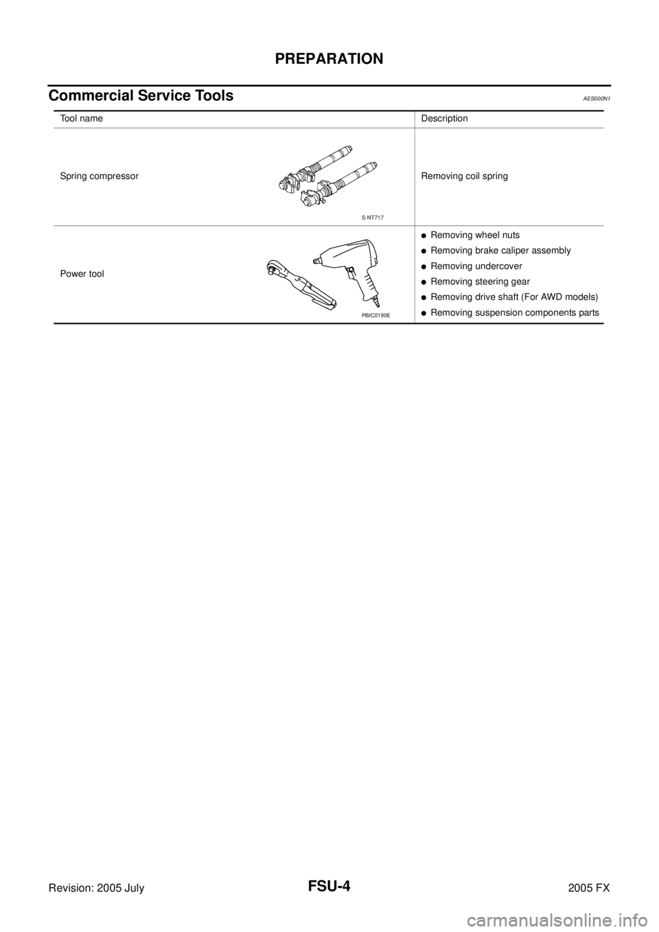
Commercial Service ToolsAES000N1
Tool nameDescription
Spring compressor Removing coil spring
Power tool
�Removing wheel nuts
�Removing brake caliper assembly
�Removing undercover
�Removing steering gear
�Removing drive shaft (For AWD models)
�Removing suspension components parts
S-NT717
PBIC0190E
Page 3208 of 4731
 TROUBLESHOOTING FSU-5
C
D
F
G H
I
J
K L
M A
B
FSU
Revision: 2005 July 2005 FX
NOISE, VIBRATION AND HARSHNESS (NVH) TROUBLESHOOTINGPFP:00003
NVH Troubl")
NOISE, VIBRATION AND HARSHNESS (NVH) TROUBLESHOOTING FSU-5
C
D
F
G H
I
J
K L
M A
B
FSU
Revision: 2005 July 2005 FX
NOISE, VIBRATION AND HARSHNESS (NVH) TROUBLESHOOTINGPFP:00003
NVH Troubleshooting ChartAES000N2
Use chart below to help you find the cause of the symptom. If necessary, repair or replace these parts.
×: Applicable Reference page
FSU-8FSU-12
—
—
—
FSU-8FSU-6FSU-16
NVH in PR section
NVH in RFD section
NVH in RAX and RSU section
NVH in WT section
NVH in WT section
NVH in RAX section NVH in BR section NVH in PS section
Possible cause and SUSPECTED PARTS
Improper installation, looseness
Strut deformation, damage or deflection
Bushing or mounting deterioration
Parts interference
Spring fatigue
Suspension looseness
Incorrect wheel alignment
Stabilizer bar fatigue
PROPELLER SHAFT (For AWD models)
DIFFERENTIAL (For AWD models)
REAR AXLE AND REAR SUSPENSION
TIRES
ROAD WHEEL
DRIVE SHAFT (For AWD models)
BRAKES
STEERING
Symptom FRONT SUSPENSION Noise
××××× × ××× ×××××
Shake ×××× × × × ×××××
Vibration ××××× × ×× × ×
Shimmy ×××× × ××× ××
Judder ××× ××× ××
Poor quality ride or han-
dling ××××× ×× ×××