Page 893 of 4731

BL-78
REMOTE KEYLESS ENTRY SYSTEM
Revision: 2005 July 2005 FX
Check Key SwitchAIS004MN
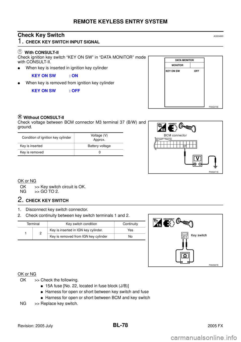
1. CHECK KEY SWITCH INPUT SIGNAL
With CONSULT-II
Check ignition key switch “KEY ON SW” in “DATA MONITOR” mode
with CONSULT-II.
�When key is inserted in ignition key cylinder
�When key is removed from ignition key cylinder
Without CONSULT-II
Check voltage between BCM connector M3 terminal 37 (B/W) and
ground.
OK or NG
OK >> Key switch circuit is OK.
NG >> GO TO 2.
2. CHECK KEY SWITCH
1. Disconnect key switch connector.
2. Check continuity between key switch terminals 1 and 2.
OK or NG
OK >> Check the following.
�15A fuse [No. 22, located in fuse block (J/B)]
�Harness for open or short between key switch and fuse
�Harness for open or short between BCM and key switch
NG >> Replace key switch. KEY ON SW : ON
KEY ON SW : OFF
PIIA6470E
Condition of ignition key cylinder Voltage (V)
Approx.
Key is inserted Battery voltage
Key is removed 0
PIIA6471E
Terminal Key switch condition Continuity
12 Key is inserted in IGN key cylinder. Yes
Key is removed from IGN key cylinder No
PIIA2627E
Page 929 of 4731

BL-114
INTELLIGENT KEY SYSTEM
Revision: 2005 July 2005 FX
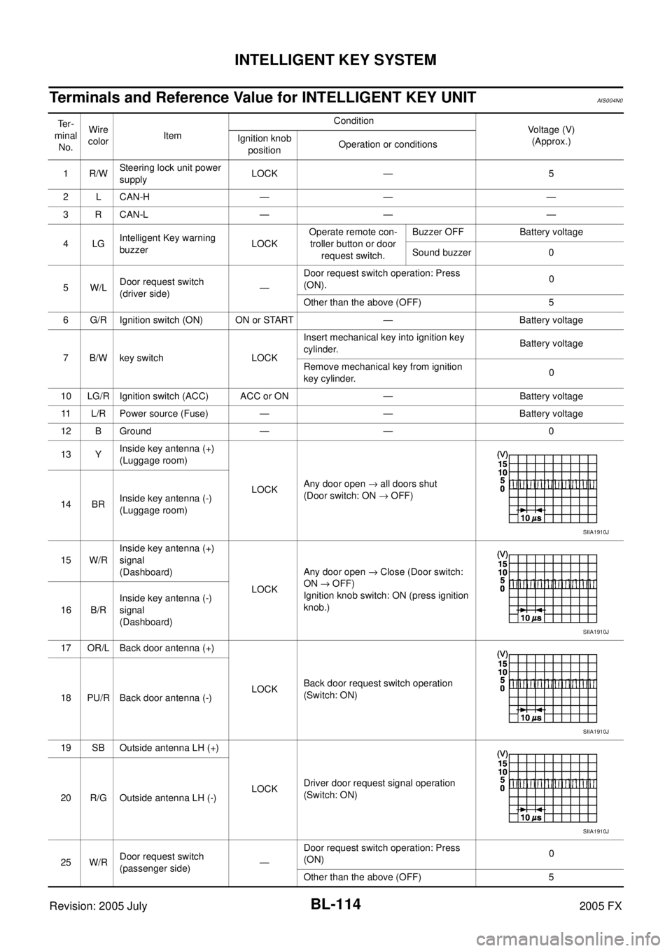
Terminals and Reference Value for INTELLIGENT KEY UNITAIS004N0
Te r -
minal No. Wire
color Item Condition
Voltage (V)
(Approx.)
Ignition knob
position Operation or conditions
1R/W Steering lock unit power
supply LOCK — 5
2 L CAN-H — — —
3 R CAN-L — — —
4LG Intelligent Key warning
buzzer LOCK Operate remote con-
troller button or door
request switch. Buzzer OFF Battery voltage
Sound buzzer 0
5W/L Door request switch
(driver side) — Door request switch operation: Press
(ON). 0
Other than the above (OFF) 5
6 G/R Ignition switch (ON) ON or START — Battery voltage
7 B/W key switch LOCK Insert mechanical key into ignition key
cylinder. Battery voltage
Remove mechanical key from ignition
key cylinder. 0
10 LG/R Ignition switch (ACC) ACC or ON — Battery voltage 11 L/R Power source (Fuse) — — Battery voltage
12 B Ground — — 0
13 Y Inside key antenna (+)
(Luggage room)
LOCK Any door open
→ all doors shut
(Door switch: ON → OFF)
14 BR Inside key antenna (-)
(Luggage room)
15 W/R Inside key antenna (+)
signal
(Dashboard)
LOCK Any door open
→ Close (Door switch:
ON → OFF)
Ignition knob switch: ON (press ignition
knob.)
16 B/R Inside key antenna (-)
signal
(Dashboard)
17 OR/L Back door antenna (+)
LOCK Back door request switch operation
(Switch: ON)
18 PU/R Back door antenna (-)
19 SB Outside antenna LH (+) LOCK Driver door request signal operation
(Switch: ON)
20 R/G Outside antenna LH (-)
25 W/R Door request switch
(passenger side) — Door request switch operation: Press
(ON) 0
Other than the above (OFF) 5
SIIA1910J
SIIA1910J
SIIA1910J
SIIA1910J
Page 931 of 4731

BL-116
INTELLIGENT KEY SYSTEM
Revision: 2005 July 2005 FX
Terminals and Reference Value for Steering Lock unitAIS004N1
Terminals and Reference Value for BCMAIS004N2
Terminal
number Wire
color Item Condition
Voltage (V)
(Approx.)
Ignition knob
position Operation or conditions
1 L/R Power source (Fuse) LOCK — Battery voltage
2R/W Steering lock unit
power supply LOCK — 5
3R/B Steering lock unit com-
munication signal LOCK Press ignition knob with Intelligent
Key inside vehicle.
Other than the above 5
4Y/B Steering lock unit
ground —— 0
SIIA1911J
Te r m i -
nal Wire
color Item Condition Voltage (V)
(Approx.)
1PU Key ring illumination output sig-
nal Key ring illumination is lighting. Battery voltage
Key ring illumination is being turned off. 0
12 P/B Front door switch (Passenger
side) Door open (ON)
→ Close (OFF) 0 → Battery voltage
13 P/L Rear door switch RH Door open (ON) → Close (OFF) 0 → Battery voltage
37 B/W Key switch Insert mechanical key from ignition key
sylinder. Battery voltage
Remove mechanical key from ignition
key cylinder. 0
38 W/L Ignition switch (ON) Ignition switch is in ON or START posi-
tion Battery voltage
39 L CAN-H — —
40 R CAN-L — —
41 R/B Battery saver output signal 30 minutes after ignition switch is turned
to OFF 0
Ignition switch is in ON position Battery voltage
42 L/R Power source (Fuse) — Battery voltage
44 Y Driver door lock actuator
(Unlock) Door lock / unlock switch
(Free → Unlock) 0
→ Battery voltage
45 G/W Left turn signal lamp When door lock or unlock is operated
using Intelligent Key.*
1
(ON → OFF) Battery voltage
→ 0
46 BR/W Right turn signal lamp When door lock or unlock is operated
using Intelligent Key.*
1
(ON → OFF) Battery voltage
→ 0
47 Y/R Step lamp output signal Step lamp is lighting. 0
Step lamp is being turned off. Battery voltage
48 PU/W Room lamp output signal Room lamp is lighting.*
20
Room lamp is being turned off.*
2Battery voltage
49 B Ground — 0
Page 945 of 4731

BL-130
INTELLIGENT KEY SYSTEM
Revision: 2005 July 2005 FX
2. CHECK KEY SWITCH POWER SUPPLY CIRCUIT
1. Remove mechanical key from ignition knob.
2. Disconnect key switch and ignition knob switch connector.
3. Check voltage between key switch and ignition knob switch connector M22 terminal 3 (L/R) and ground.
OK or NG
OK >> GO TO 3.
NG >> Repair or replace key switch power supply circuit.
3. CHECK KEY SWITCH OPERATION
Check continuity between key switch and ignition knob switch terminals 3 and 4.
OK or NG
OK >> GO TO 4.
NG >> Replace key switch.
4. CHECK KEY SWITCH CIRCUIT
1. Disconnect Intelligent Key unit connector.
2. Check continuity between Intelligent Key unit connector M34 terminal 7 (B/W) and key switch and ignition knob switch connector M22 terminal 4 (B/W).
3. Check continuity between key switch and ignition knob switch connector M22 terminal 4 (B/W) and ground.
OK or NG
OK >> Replace Intelligent key unit.
NG >> Repair or replace harness between Intelligent Key unit and key switch and ignition knob switch.
3 (L/R) - Ground : Battery voltage
PIIA6738E
Terminals Condition Continuity
34 Key is inserted in ignition key cylinder. Yes
Key is removed from ignition key cylinder. No
PIIA6140E
7 (B/W) - 4 (B/W) : Continuity should exist.
4 (B/W) - Ground : Continuity should not exist.
PIIA6740E
Page 946 of 4731

INTELLIGENT KEY SYSTEM BL-131
C
D E
F
G H
J
K L
M A
B
BL
Revision: 2005 July 2005 FX
Check Key Switch (BCM Input)AIS004ND
1. CHECK KEY SWITCH POWER SUPPLY CIRCUIT
1. Turn ignition knob OFF position.
2. Disconnect key switch and ignition knob switch connector.
3. Check voltage between key switch and ignition knob switch con- nector M22 terminal 3 (L/R) and ground.
OK or NG
OK >> GO TO 2.
NG >> Check harness between key switch and ignition knob switch and fuse.
2. CHECK KEY SWITCH
Check continuity between key switch and ignition knob switch as fol-
lows.
OK or NG
OK >> GO TO 3.
NG >> Replace key switch and ignition knob switch.
3. CHECK KEY SWITCH SIGNAL CIRCUIT
1. Disconnect key switch and ignition knob switch connector and BCM connector.
2. Check continuity between key switch and ignition knob switch connector M22 terminal 4 (B/W) and BCM connector M3 termi-
nal 37 (B/W).
3. Check continuity between key switch and ignition knob switch connector M22 terminal 4 (B/W) and ground.
OK or NG
OK >> Key switch (BCM input) circuit is OK.
NG >> Repair or replace harness between key switch and ignition knob switch and BCM. 3 (L/R) – Ground : Battery voltage.
PIIA5093E
Terminals Condition Continuity
34 Key is inserted in ignition key cylinder. Yes
Key is removed from ignition key cylinder. No
PIIA6140E
4 (B/W) – 37 (B/W) : Continuity should exist.
4 (B/W) – Ground : Continuity should not exist.
PIIA5095E
Page 972 of 4731

FRONT DOOR LOCK BL-157
C
D E
F
G H
J
K L
M A
B
BL
Revision: 2005 July 2005 FX
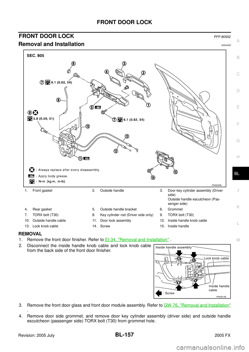
FRONT DOOR LOCKPFP:80502
Removal and InstallationAIS004NZ
REMOVAL
1. Remove the front door finisher. Refer to EI-34, "Removal and Installation" .
2. Disconnect the inside handle knob cable and lock knob cable from the back side of the front door finisher.
3. Remove the front door glass and front door module assembly. Refer to GW-76, "
Removal and Installation"
.
4. Remove door side grommet, and remove door key cylinder assembly (driver side) and outside handle escutcheon (passenger side) TORX bolt (T30) from grommet hole.
1. Front gasket 2. Outside handle 3. Door key cylinder assembly (Driver
side)
Outside handle escutcheon (Pas-
senger side)
4. Rear gasket 5. Outside handle bracket 6. Grommet
7. TORX bolt (T30) 8. Key cylinder rod (Driver side only) 9. TORX bolt (T30)
10. Outside handle cable 11. Door lock assembly 12. Inside handle knob cable
13. Lock knob cable 14. Screw 15. Inside handle
PIIA6025E
PIIA4014E
Page 973 of 4731
BL-158
FRONT DOOR LOCK
Revision: 2005 July 2005 FX
CAUTION:
Do not forcibly remove the TORX bolt (T30).
5. Reach to separate the key cylinder rod connection (on the handle).
6. While pulling the outside handle, remove door key cylinder assembly (driver side) and outside handle escutcheon (passen-
ger side).
7. Disconnect the door request switch connector. (Intelligent Key only)
8. While pulling outside handle, slide toward rear of vehicle to remove outside handle.
9. Remove the front gasket and rear gasket.
PIIA3553E
PIIA3554E
PIIA3555E
PIIA3557E
Page 975 of 4731
BL-160
FRONT DOOR LOCK
Revision: 2005 July 2005 FX
Disassembly and AssemblyAIS004O1
DOOR KEY CYLINDER ASSEMBLY
Remove the key cylinder escutcheon pawl and remove the door key cylinder.
1. Door key cylinder assembly 2. Key cylinder escutcheon 3. Door key cylinder
PIIA6431E