Page 1040 of 4731
IVIS (INFINITI VEHICLE IMMOBILIZER SYSTEM-NATS) BL-225
C
D E
F
G H
J
K L
M A
B
BL
Revision: 2005 July 2005 FX
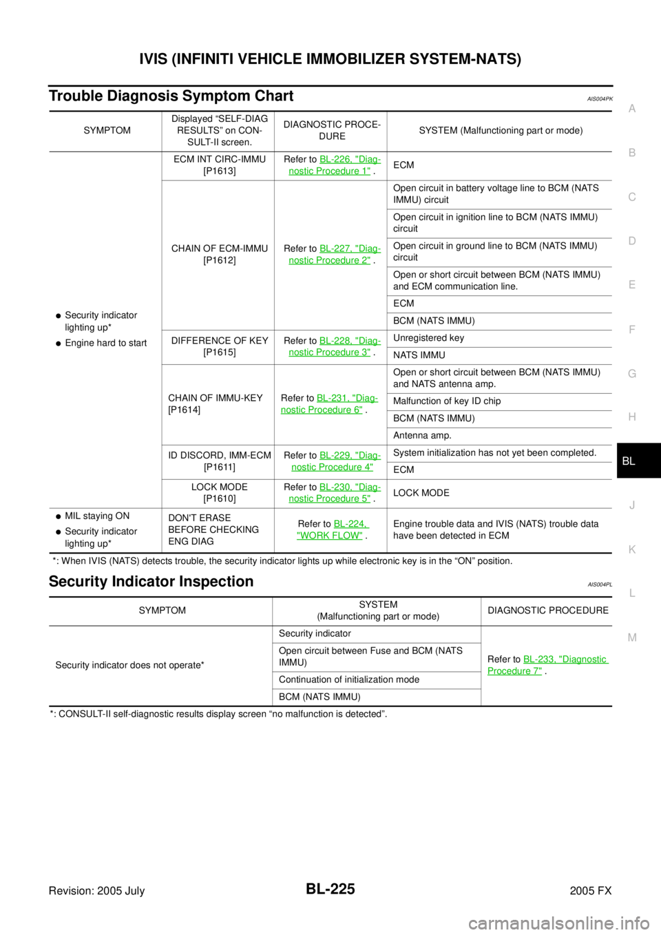
Trouble Diagnosis Symptom ChartAIS004PK
*: When IVIS (NATS) detects trouble, the security indicator lights up while electronic key is in the “ON” position.
Security Indicator InspectionAIS004PL
*: CONSULT-II self-diagnostic results display screen “no malfunction is detected”. SYMPTOM
Displayed “SELF-DIAG
RESULTS” on CON- SULT-II screen. DIAGNOSTIC PROCE-
DURE SYSTEM (Malfunctioning part or mode)
�Security indicator
lighting up*
�Engine hard to start ECM INT CIRC-IMMU
[P1613] Refer to
BL-226, "
Diag-
nostic Procedure 1" . ECM
CHAIN OF ECM-IMMU [P1612] Refer to
BL-227, "
Diag-
nostic Procedure 2" . Open circuit in battery voltage line to BCM (NATS
IMMU) circuit
Open circuit in ignition line to BCM (NATS IMMU)
circuit
Open circuit in ground line to BCM (NATS IMMU)
circuit
Open or short circuit between BCM (NATS IMMU)
and ECM communication line.
ECM
BCM (NATS IMMU)
DIFFERENCE OF KEY [P1615] Refer to
BL-228, "
Diag-
nostic Procedure 3" . Unregistered key
NATS IMMU
CHAIN OF IMMU-KEY
[P1614] Refer to
BL-231, "
Diag-
nostic Procedure 6" . Open or short circuit between BCM (NATS IMMU)
and NATS antenna amp.
Malfunction of key ID chip
BCM (NATS IMMU)
Antenna amp.
ID DISCORD, IMM-ECM [P1611] Refer to
BL-229, "
Diag-
nostic Procedure 4"
System initialization has not yet been completed.
ECM
LOCK MODE [P1610] Refer to
BL-230, "
Diag-
nostic Procedure 5" . LOCK MODE
�MIL staying ON
�Security indicator
lighting up* DON'T ERASE
BEFORE CHECKING
ENG DIAG Refer to
BL-224, "WORK FLOW" . Engine trouble data and IVIS (NATS) trouble data
have been detected in ECM
SYMPTOM SYSTEM
(Malfunctioning part or mode) DIAGNOSTIC PROCEDURE
Security indicator does not operate* Security indicator
Refer to BL-233, "
Diagnostic
Procedure 7" .
Open circuit between Fuse and BCM (NATS
IMMU)
Continuation of initialization mode
BCM (NATS IMMU)
Page 1043 of 4731
BL-228
IVIS (INFINITI VEHICLE IMMOBILIZER SYSTEM-NATS)
Revision: 2005 July 2005 FX
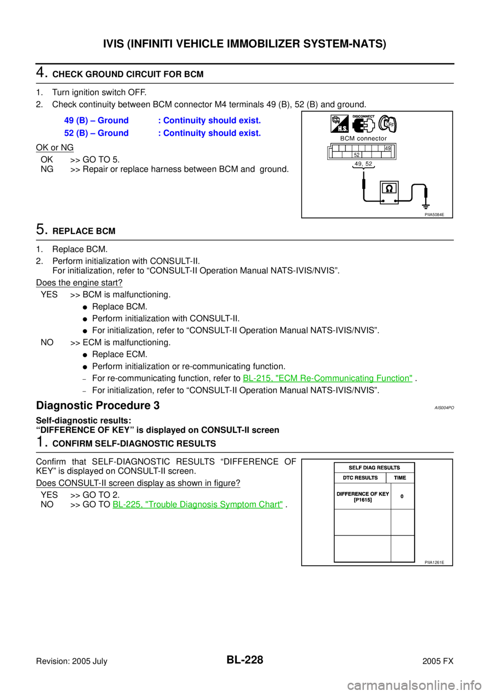
4. CHECK GROUND CIRCUIT FOR BCM
1. Turn ignition switch OFF.
2. Check continuity between BCM connector M4 terminals 49 (B), 52 (B) and ground.
OK or NG
OK >> GO TO 5.
NG >> Repair or replace harness between BCM and ground.
5. REPLACE BCM
1. Replace BCM.
2. Perform initialization with CONSULT-II. For initialization, refer to “CONSULT-II Operation Manual NATS-IVIS/NVIS”.
Does the engine start?
YES >> BCM is malfunctioning.
�Replace BCM.
�Perform initialization with CONSULT-II.
�For initialization, refer to “CONSULT-II Operation Manual NATS-IVIS/NVIS”.
NO >> ECM is malfunctioning.
�Replace ECM.
�Perform initialization or re-communicating function.
–For re-communicating function, refer to BL-215, "ECM Re-Communicating Function" .
–For initialization, refer to “CONSULT-II Operation Manual NATS-IVIS/NVIS”.
Diagnostic Procedure 3AIS004PO
Self-diagnostic results:
“DIFFERENCE OF KEY” is displayed on CONSULT-II screen
1. CONFIRM SELF-DIAGNOSTIC RESULTS
Confirm that SELF-DIAGNOSTIC RESULTS “DIFFERENCE OF
KEY” is displayed on CONSULT-II screen.
Does CONSULT-II screen display as shown in figure?
YES >> GO TO 2.
NO >> GO TO BL-225, "
Trouble Diagnosis Symptom Chart" .
49 (B) – Ground : Continuity should exist.
52 (B) – Ground : Continuity should exist.
PIIA5084E
PIIA1261E
Page 1044 of 4731
IVIS (INFINITI VEHICLE IMMOBILIZER SYSTEM-NATS) BL-229
C
D E
F
G H
J
K L
M A
B
BL
Revision: 2005 July 2005 FX
2. PERFORM INITIALIZATION WITH CONSULT-II
Perform initialization with CONSULT-II. Re-register all ignition key or mechanical key IDs.
For initialization and registration of ignition key or mechanical key IDs, refer to “CONSULT-II Operation Manual
NATS-IVIS/NVIS”.
NOTE:
If the initialization is not completed or malfunction, CONSULT-II
shows message on the screen.
Can the system be initialized and can the engine be started with re-
registered ignition key or mechanical key?
YES >> Ignition key ID was unregistered.
NO >> BCM is malfunctioning.
�Replace BCM.
�Perform initialization with CONSULT-II.
�For initialization, refer to “CONSULT-II Operation
Manual NATS-IVIS/NVIS”.
Diagnostic Procedure 4AIS004PP
Self-diagnostic results:
“ID DISCORD, IMM-ECM” is displayed on CONSULT-II screen
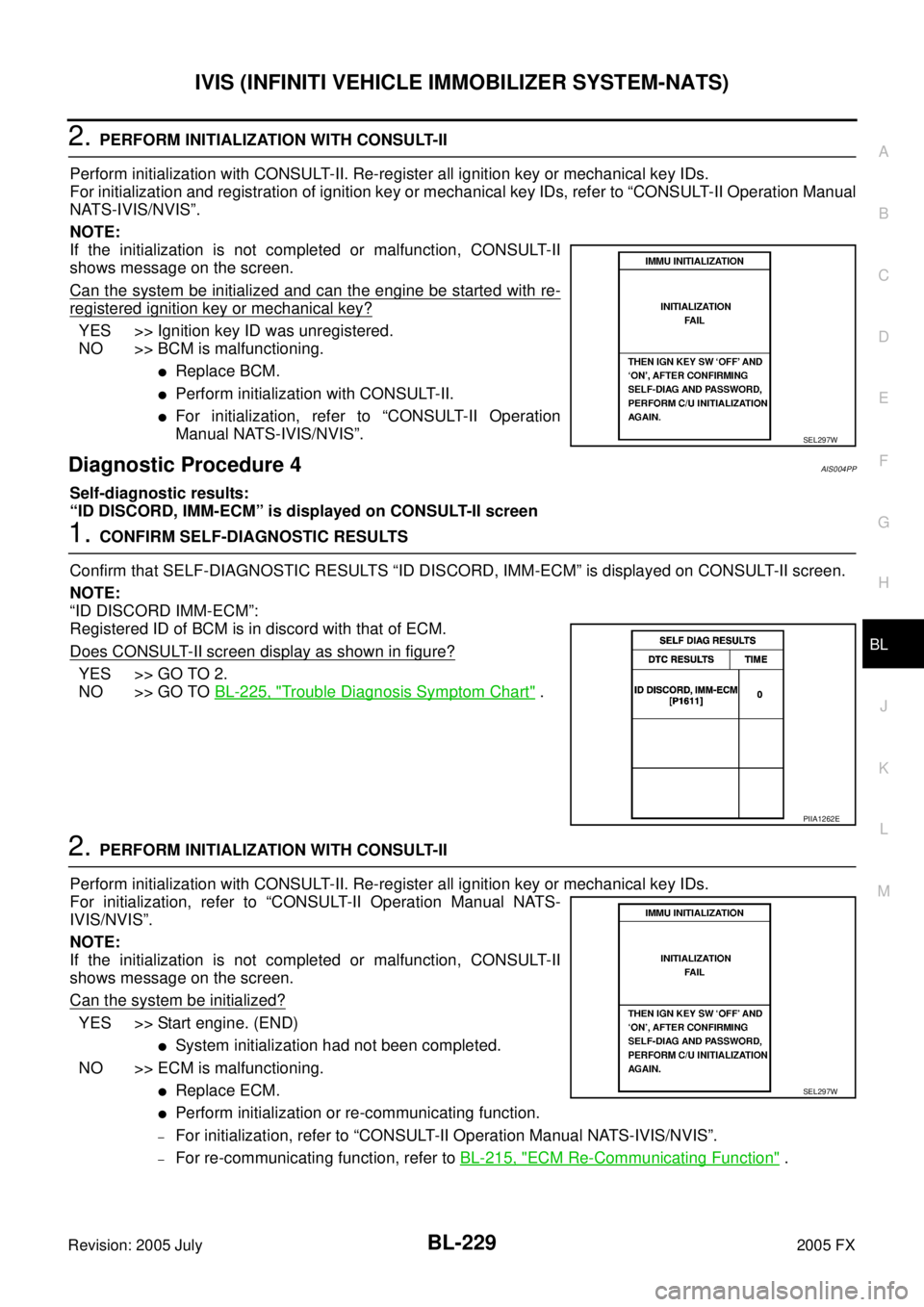
1. CONFIRM SELF-DIAGNOSTIC RESULTS
Confirm that SELF-DIAGNOSTIC RESULTS “ID DISCORD, IMM-ECM” is displayed on CONSULT-II screen.
NOTE:
“ID DISCORD IMM-ECM”:
Registered ID of BCM is in discord with that of ECM.
Does CONSULT-II screen display as shown in figure?
YES >> GO TO 2.
NO >> GO TO BL-225, "
Trouble Diagnosis Symptom Chart" .
2. PERFORM INITIALIZATION WITH CONSULT-II
Perform initialization with CONSULT-II. Re-register all ignition key or mechanical key IDs.
For initialization, refer to “CONSULT-II Operation Manual NATS-
IVIS/NVIS”.
NOTE:
If the initialization is not completed or malfunction, CONSULT-II
shows message on the screen.
Can the system be initialized?
YES >> Start engine. (END)
�System initialization had not been completed.
NO >> ECM is malfunctioning.
�Replace ECM.
�Perform initialization or re-communicating function.
–For initialization, refer to “CONSULT-II Operation Manual NATS-IVIS/NVIS”.
–For re-communicating function, refer to BL-215, "ECM Re-Communicating Function" .
SEL297W
PIIA1262E
SEL297W
Page 1045 of 4731
BL-230
IVIS (INFINITI VEHICLE IMMOBILIZER SYSTEM-NATS)
Revision: 2005 July 2005 FX
Diagnostic Procedure 5AIS004PQ
Self-diagnostic results:
“LOCK MODE” displayed on CONSULT-II screen
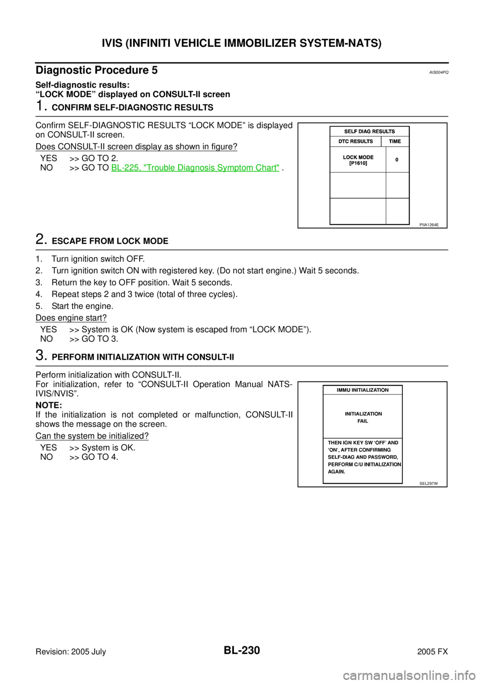
1. CONFIRM SELF-DIAGNOSTIC RESULTS
Confirm SELF-DIAGNOSTIC RESULTS “LOCK MODE” is displayed
on CONSULT-II screen.
Does CONSULT-II screen display as shown in figure?
YES >> GO TO 2.
NO >> GO TO BL-225, "
Trouble Diagnosis Symptom Chart" .
2. ESCAPE FROM LOCK MODE
1. Turn ignition switch OFF.
2. Turn ignition switch ON with registered key. (Do not start engine.) Wait 5 seconds.
3. Return the key to OFF position. Wait 5 seconds.
4. Repeat steps 2 and 3 twice (total of three cycles).
5. Start the engine.
Does engine start?
YES >> System is OK (Now system is escaped from “LOCK MODE”).
NO >> GO TO 3.
3. PERFORM INITIALIZATION WITH CONSULT-II
Perform initialization with CONSULT-II.
For initialization, refer to “CONSULT-II Operation Manual NATS-
IVIS/NVIS”.
NOTE:
If the initialization is not completed or malfunction, CONSULT-II
shows the message on the screen.
Can the system be initialized?
YES >> System is OK.
NO >> GO TO 4.
PIIA1264E
SEL297W
Page 1046 of 4731
IVIS (INFINITI VEHICLE IMMOBILIZER SYSTEM-NATS) BL-231
C
D E
F
G H
J
K L
M A
B
BL
Revision: 2005 July 2005 FX
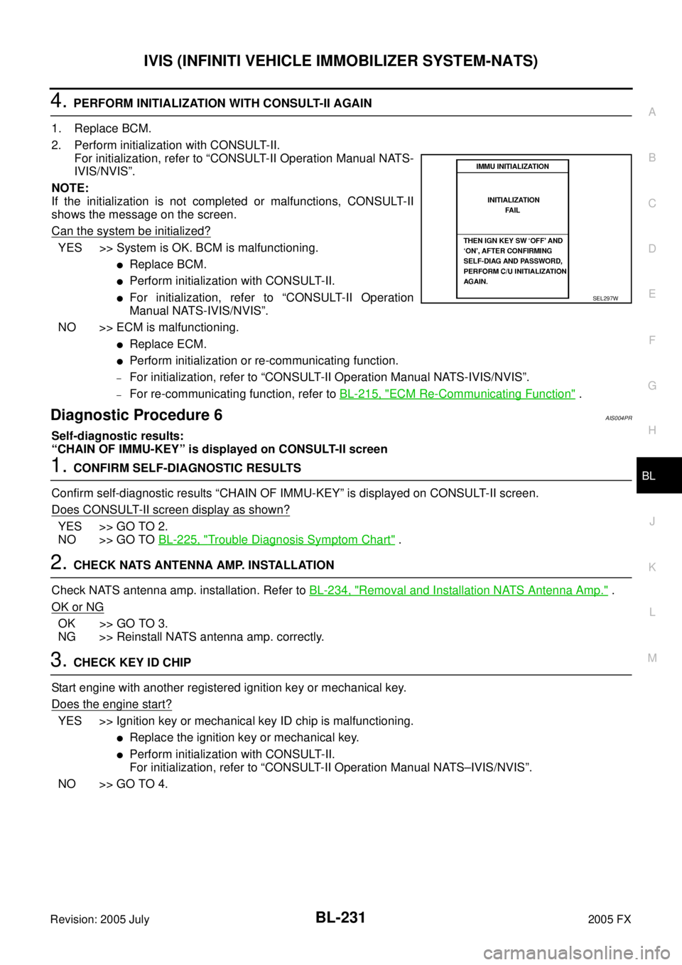
4. PERFORM INITIALIZATION WITH CONSULT-II AGAIN
1. Replace BCM.
2. Perform initialization with CONSULT-II. For initialization, refer to “CONSULT-II Operation Manual NATS-
IVIS/NVIS”.
NOTE:
If the initialization is not completed or malfunctions, CONSULT-II
shows the message on the screen.
Can the system be initialized?
YES >> System is OK. BCM is malfunctioning.
�Replace BCM.
�Perform initialization with CONSULT-II.
�For initialization, refer to “CONSULT-II Operation
Manual NATS-IVIS/NVIS”.
NO >> ECM is malfunctioning.
�Replace ECM.
�Perform initialization or re-communicating function.
–For initialization, refer to “CONSULT-II Operation Manual NATS-IVIS/NVIS”.
–For re-communicating function, refer to BL-215, "ECM Re-Communicating Function" .
Diagnostic Procedure 6AIS004PR
Self-diagnostic results:
“CHAIN OF IMMU-KEY” is displayed on CONSULT-II screen
1. CONFIRM SELF-DIAGNOSTIC RESULTS
Confirm self-diagnostic results “CHAIN OF IMMU-KEY” is displayed on CONSULT-II screen.
Does CONSULT-II screen display as shown?
YES >> GO TO 2.
NO >> GO TO BL-225, "
Trouble Diagnosis Symptom Chart" .
2. CHECK NATS ANTENNA AMP. INSTALLATION
Check NATS antenna amp. installation. Refer to BL-234, "
Removal and Installation NATS Antenna Amp." .
OK or NG
OK >> GO TO 3.
NG >> Reinstall NATS antenna amp. correctly.
3. CHECK KEY ID CHIP
Start engine with another registered ignition key or mechanical key.
Does the engine start?
YES >> Ignition key or mechanical key ID chip is malfunctioning.
�Replace the ignition key or mechanical key.
�Perform initialization with CONSULT-II.
For initialization, refer to “CONSULT-II Operation Manual NATS–IVIS/NVIS”.
NO >> GO TO 4.
SEL297W
Page 1048 of 4731
IVIS (INFINITI VEHICLE IMMOBILIZER SYSTEM-NATS) BL-233
C
D E
F
G H
J
K L
M A
B
BL
Revision: 2005 July 2005 FX
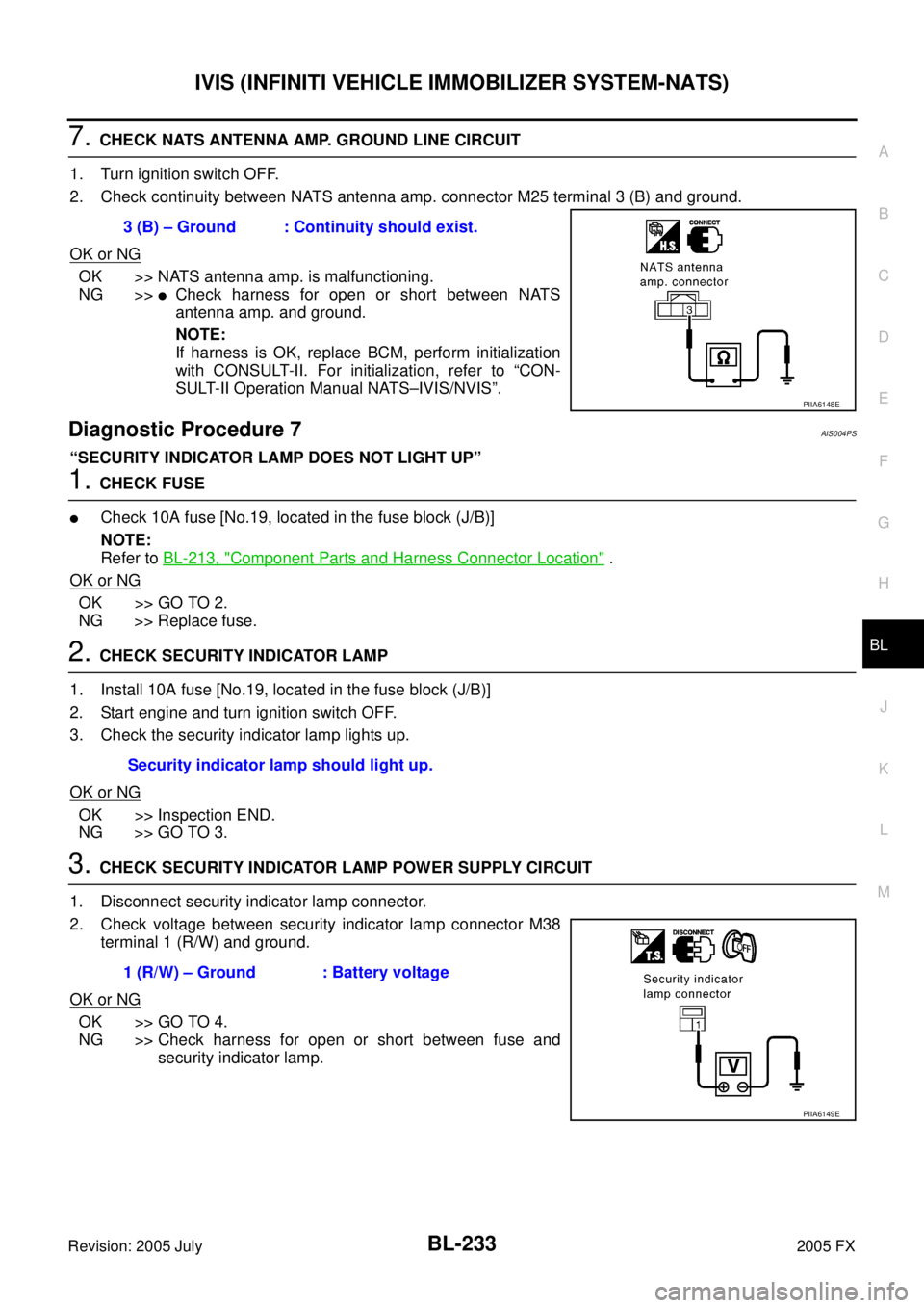
7. CHECK NATS ANTENNA AMP. GROUND LINE CIRCUIT
1. Turn ignition switch OFF.
2. Check continuity between NATS antenna amp. connector M25 terminal 3 (B) and ground.
OK or NG
OK >> NATS antenna amp. is malfunctioning.
NG >>
�Check harness for open or short between NATS
antenna amp. and ground.
NOTE:
If harness is OK, replace BCM, perform initialization
with CONSULT-II. For initialization, refer to “CON-
SULT-II Operation Manual NATS–IVIS/NVIS”.
Diagnostic Procedure 7AIS004PS
“SECURITY INDICATOR LAMP DOES NOT LIGHT UP”
1. CHECK FUSE
�Check 10A fuse [No.19, located in the fuse block (J/B)]
NOTE:
Refer to BL-213, "
Component Parts and Harness Connector Location" .
OK or NG
OK >> GO TO 2.
NG >> Replace fuse.
2. CHECK SECURITY INDICATOR LAMP
1. Install 10A fuse [No.19, located in the fuse block (J/B)]
2. Start engine and turn ignition switch OFF.
3. Check the security indicator lamp lights up.
OK or NG
OK >> Inspection END.
NG >> GO TO 3.
3. CHECK SECURITY INDICATOR LAMP POWER SUPPLY CIRCUIT
1. Disconnect security indicator lamp connector.
2. Check voltage between security indicator lamp connector M38 terminal 1 (R/W) and ground.
OK or NG
OK >> GO TO 4.
NG >> Check harness for open or short between fuse and security indicator lamp.
3 (B) – Ground : Continuity should exist.
PIIA6148E
Security indicator lamp should light up.
1 (R/W) – Ground : Battery voltage
PIIA6149E
Page 1069 of 4731
BL-254
BODY REPAIR
Revision: 2005 July2005 FX
ENGINE COMPARTMENT
Measurement
SIIA2260E
Page 1115 of 4731
BR-6
BRAKE PEDAL
Revision: 2005 July 2005 FX
BRAKE PEDALPFP:46501
Inspection and AdjustmentAFS001MT
PLAY AND CLEARANCE BETWEEN BRAKE PEDAL AND FLOOR PANEL WITH PEDAL
DEPRESSED
1. Check brake pedal height from dash lower panel.
2. Adjust height referring to the following specifications.
SFIA1450E
H Brake pedal free height (from dash lower panel
top surface) 161.5
− 171.5 mm (6.36 − 6.75 in)
D Brake pedal depressed height [under a force of
490 N (50 kg, 110 lb) with engine running] More than 80 mm (3.15 in)
C Clearance between bracket and the threaded end
of stop lamp switch or ASCD cancel switch (or
brake switch) 0.74
− 1.96 mm (0.0291 −0.0772 in)
A Pedal play 3 − 11 mm (0.12 − 0.43 in)