Page 682 of 4731
INTEGRATED DISPLAY SYSTEM AV-83
C
D E
F
G H
I
J
L
M A
B
AV
Revision: 2005 July 2005 FX
3. CHECK AUDIO COMMUNICATION SIGNAL(AUD–DSP)
1. Turn ignition switch OFF and connect audio unit connector.
2. Turn ignition switch ON.
3. Check voltage between audio unit harness connector M60 ter- minal 21 (B/Y) and ground.
OK or NG
OK >> GO TO 4.
NG >> Replace audio unit.
4. CHECK AUDIO COMMUNICATION SIGNAL(DSP–AUD)
1. Turn ignition switch ON.
2. Check the signal between display unit harness connector M62 terminal 8 (LG) and ground with CONSULT-ll or oscilloscope.
OK or NG
OK >> GO TO 5.
NG >> Replace display unit.
5. CHECK AUDIO COMMUNICATION SIGNAL(AUD–DSP)
1. Turn ignition switch ON.
2. Check the signal between display unit harness connector M62 terminal 10 (B/Y) and ground with CONSULT-ll or oscilloscope.
OK or NG
OK >> INSPECTION END
NG >> Replace audio unit. Approx. 3.5 V or more
SKIA4996E
8 (LG) - Ground:
SKIA4995ESKIA4402E
10 (B/Y) - Ground:
SKIA4999ESKIA4403E
Page 683 of 4731
AV-84
INTEGRATED DISPLAY SYSTEM
Revision: 2005 July 2005 FX
AV Communication Line InspectionAKS005UI
1. CHECK A/C AND AV SWITCH CIRCUIT
1. Turn ignition switch OFF.
2. Disconnect display unit connector and A/C and AV switch connector.
3. Check continuity between display unit and A/C and AV switch.
4. Check continuity between display unit and ground.
OK or NG
OK >> GO TO 2.
NG >> Repair harness or connector.
2. CHECK OF A/C AND AV SWITCH
Replace same normal A/C and AV switch and recheck the symptom.
Is the function normal?
YES >> Replace A/C and AV switch.
NO >> Replace display unit.
Terminals
Continuity
Display unit A/C and AV switch
Connector Terminal
(Wire color) Connector Te r m i n a l
(Wire color)
M62 11 (B/R)
M64 6 (B/R)
Ye s
13 (W/R) 8 (W/R)
12 7
SKIA5002E
Te r m i n a l s Continuity
Connector Terminal (Wire color) Terminal
M62 11 (B/R)
Ground No
13 (W/R)
SKIA7146E
Page 684 of 4731

INTEGRATED DISPLAY SYSTEM AV-85
C
D E
F
G H
I
J
L
M A
B
AV
Revision: 2005 July 2005 FX
CAN Communication Line InspectionAKS005UJ
1. CHECK MONITOR DESCRIPTION
1. Start display unit self-diagnosis. Refer to AV- 7 4 , "
Self-Diagnosis Mode" .
2. Select “CAN DIAG MNTR”. Refer to AV- 7 6 , "
CAN DIAG MNTR (CAN DIAG MONITOR)" .
3. Record each item display description (OK/NG/UKNWN) displayed on the following CAN DIAG MONITOR Check Sheet.
CAN DIAG MONITOR Check Sheet
>> After filling in CAN DIAG MONITOR Check Sheet, go to LAN-5, "
Precautions When Using CON-
SULT-II" .
Diagnosis item Data monitor display description
Normal condition Abnormal condition
(example)
CANCOMM OK NG CAN1 OK UNKWN
CAN2 OK UNKWN
CAN3 OK UNKWN
CAN4 OK UNKWN
CAN5 OK UNKWN
CAN6 OK UNKWN
CAN7 OK UNKWN
CAN8 OK UNKWN
CAN9 OK UNKWN
SKIA5927E
Diagnosis item Screen display Diagnosis item Screen display CANCOMM OK NG CAN5 OK UNKWN CAN1 OK UNKWN CAN6 OK UNKWN
CAN2 OK UNKWN CAN7 OK UNKWN
CAN3 OK UNKWN CAN8 OK UNKWN
CAN4 OK UNKWN CAN9 OK UNKWN
Page 685 of 4731
AV-86
INTEGRATED DISPLAY SYSTEM
Revision: 2005 July 2005 FX
Audio Steering Wheel Switch InspectionAKS005UK
Refer to AV- 4 2 , "Audio Steering Wheel Switch Inspection" .
Removal and Installation of DisplayAKS005UL
REMOVAL
1. Remove audio unit. Refer to AV- 4 7 , "Removal and Installation of
Audio Unit" .
2. Remove screws (4), and remove display.
INSTALLATION
Installation is the reverse order of removal.
Removal and Installation of A/C and AV SwitchAKS005UM
Refer to AV- 4 8 , "Removal and Installation for A/C and AV Switch" .
SKIA6167E
Page 686 of 4731

NAVIGATION SYSTEM AV-87
C
D E
F
G H
I
J
L
M A
B
AV
Revision: 2005 July 2005 FX
NAVIGATION SYSTEMPFP:25915
System DescriptionAKS007IQ
The navigation system periodically calculates the vehicle's current
position according to the following three signals: Travel distance of
the vehicle as determined by the vehicle speed sensor, turning angle
of the vehicle as determined by the gyroscope (angular velocity sen-
sor), and the direction of vehicle travel as determined by the GPS
antenna (GPS information).
The current position of the vehicle is then identified by comparing the
calculated vehicle position with map data read from the map DVD-
ROM, which is stored in the DVD-ROM drive (map-matching), and
indicated on the screen with a current-location mark.
By comparing the vehicle position detection results found by the
GPS and by map-matching, more accurate vehicle position data can
be used.
The current vehicle position will be calculated by detecting the dis-
tance the vehicle moved from the previous calculation point and its
direction.
TRAVEL DISTANCE
Travel distance calculations are based on the vehicle speed sensor input signal. Therefore, the calculation
may become incorrect as the tires wear down. To prevent this, an automatic distance fine adjustment function
has been adopted.
TRAVEL DIRECTION
Change in the travel direction of the vehicle is calculated by a gyroscope (angular velocity sensor) and a GPS
antenna (GPS information). As the gyroscope and GPS antenna have both merit and demerit, input signals
from them are prioritized in each situation. However, this order of priority may change in accordance with more
detailed travel conditions so that the travel direction is detected more accurately.
MAP-MATCHING
Map-matching is a function that repositions the vehicle on the road
map when a new location is judged to be the most accurate. This is
done by comparing the current vehicle position, calculated by the
method described in the position detection principle, with the road
map data around the vehicle, read from the map DVD-ROM stored in
the DVD-ROM drive.
Therefore, the vehicle position may not be corrected after the vehicle
is driven over a certain distance or time in which GPS information is
hard to receive. In this case, the current location mark on the display
must be corrected manually.
CAUTION:
The road map data is based on data stored in the map DVD-
ROM.
SKIA6215E
SEL684V
Type Advantage Disadvantage
Gyroscope
(angular velocity sensor)
�Can detect the vehicle's turning angle
quite accurately.�Direction errors may accumulate when the vehicle is
driven for long distances without stopping.
GPS antenna
(GPS information)
�Can detect the vehicle's travel direction
(North/South/East/West).�Correct direction cannot be detected when the vehicle
speed is low.
SEL685V
Page 688 of 4731
 and the DVD-ROM drive are
built-")
NAVIGATION SYSTEM AV-89
C
D E
F
G H
I
J
L
M A
B
AV
Revision: 2005 July 2005 FX
COMPONENT DESCRIPTION
NAVI Control Unit
�The gyro (angular speed sensor) and the DVD-ROM drive are
built-in units that control the navigation functions.
�Signals are received from the gyro, the vehicle speed sensor,
and the GPS antenna. Vehicle location is determined by com-
bining this data with the data contained in the DVD-ROM map.
Locational information is shown on LCD panel.
DVD-ROM Drive
Maps, traffic control regulations, and other pertinent information can
be easily read from the DVD-ROM disc.
Map DVD-ROM
�The map DVD-ROM has maps, traffic control regulations, and other pertinent information.
�To improve DVD-ROM map matching and route determination functions, the DVD-ROM uses an exclusive
Nissan format. Therefore, the use of a DVD-ROM provided by other manufacturers cannot be used.
Gyro (Angular Speed Sensor)
�The oscillator gyro sensor is used to detect changes in vehicle steering angle.
�The gyro is built into the navigation (NAVI) control unit.
BIRDVIEW™
The BIRDVIEW™ provides a detailed and easily seen display of road conditions covering the vehicle's imme-
diate to distant area.
�MAP DISPLAY
PKIA0248E
PKIA0249E
SKIA6098E
Page 689 of 4731
AV-90
NAVIGATION SYSTEM
Revision: 2005 July 2005 FX
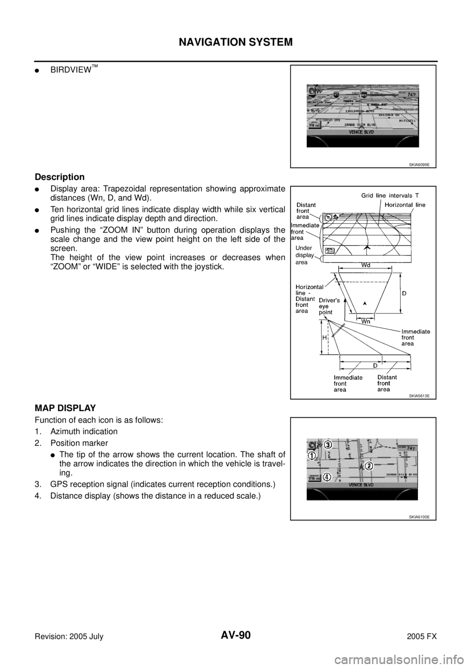
�BIRDVIEW™
Description
�Display area: Trapezoidal representation showing approximate
distances (Wn, D, and Wd).
�Ten horizontal grid lines indicate display width while six vertical
grid lines indicate display depth and direction.
�Pushing the “ZOOM IN” button during operation displays the
scale change and the view point height on the left side of the
screen.
The height of the view point increases or decreases when
“ZOOM” or “WIDE” is selected with the joystick.
MAP DISPLAY
Function of each icon is as follows:
1. Azimuth indication
2. Position marker
�The tip of the arrow shows the current location. The shaft of
the arrow indicates the direction in which the vehicle is travel-
ing.
3. GPS reception signal (indicates current reception conditions.)
4. Distance display (shows the distance in a reduced scale.)
SKIA6099E
SKIA5613E
SKIA6100E
Page 690 of 4731

NAVIGATION SYSTEM AV-91
C
D E
F
G H
I
J
L
M A
B
AV
Revision: 2005 July 2005 FX
FUNCTION OF CENTER SWITCH
Display with Pushed “DEST” Button
�Easy Mode
�Expert Mode
The function of each icon is as follows:
SKIB3188E
SKIB3189E
Icon Mode
Description
Easy Expert
Address Book ×Favorite place can be saved to memory.
Street Address ××The destination can be searched from the address.
Point of Interest (POI) ××The destination of favorite facility can be searched.
Previous Dest. ×The previous ten destinations stored in memory are displayed.
Intersection ×The destination can be searched from the intersection.
City ×The destination can be searched from city name.
Map ×The destination can be searched from the map.
Phone Number × When two or more countries are included in one DVD-ROM, the destination can be
searched for under the country name.
Home ×Sets the home as a destination.
Help ×Explanation of navigational functions appear on the display.
Country ××Select country (USA, CANADA).

1. Turn ignition switch OFF and connect audio unit c")