Page 1228 of 4731
![INFINITI FX35 2005 Service Manual WATER PUMP CO-23
[VQ35DE]
C
D E
F
G H
I
J
K L
M A
CO
Revision: 2005 July 2005 FX
7. Remove timing chain tensioner (primary) as follows:
a. Pull lever down and release plunger stopper tab INFINITI FX35 2005 Service Manual WATER PUMP CO-23
[VQ35DE]
C
D E
F
G H
I
J
K L
M A
CO
Revision: 2005 July 2005 FX
7. Remove timing chain tensioner (primary) as follows:
a. Pull lever down and release plunger stopper tab](/manual-img/42/57020/w960_57020-1227.png)
WATER PUMP CO-23
[VQ35DE]
C
D E
F
G H
I
J
K L
M A
CO
Revision: 2005 July 2005 FX
7. Remove timing chain tensioner (primary) as follows:
a. Pull lever down and release plunger stopper tab.
�Plunger stopper tab can be pushed up to release (coaxial
structure with lever).
b. Insert a stopper pin into tensioner body hole to hold lever, and keep tab released.
NOTE:
An allen wrench [2.5 mm (0.098 in)] is used for the stopper pin
as an example.
c. Insert plunger into tensioner body by pressing slack guide.
d. Keep slack guide pressed and hold plunger in by pushing stop- per pin through the lever hole and tensioner body hole.
e. Turn crankshaft pulley clockwise so that timing chain on the tim- ing chain tensioner (primary) side is loose.
f. Remove mounting bolts and remove timing chain tensioner (pri- mary).
CAUTION:
Be careful not to drop mounting bolts inside timing chain
case.
8. Remove water pump as follows:
a. Remove three water pump mounting bolts. Secure a gap between water pump gear and timing chain, by turning crank-
shaft pulley counterclockwise until timing chain looseness on
water pump sprocket becomes maximum.
PBIC2112E
PBIC1805E
PBIC2113E
PBIC1193E
Page 1234 of 4731
WATER OUTLET AND WATER PIPING CO-29
[VQ35DE]
C
D E
F
G H
I
J
K L
M A
CO
Revision: 2005 July 2005 FX
INSTALLATION
Note the following, and install in the reverse order of removal.
�Securely insert each hose, and install clamp at a position where it does not interfere with the pipe bulge.
�When inserting water pipe into water outlet, apply neutral detergent to O-ring.
INSPECTION AFTER INSTALLATION
�Check for leaks of engine coolant using the radiator cap tester adapter [SST: EG17650301 (J33984-A)]
and the radiator cap tester (commercial service tool). Refer to CO-11, "
LEAK CHECK" .
�Start and warm up the engine. Visually make sure that there is no leaks of engine coolant.
Page 1253 of 4731
![INFINITI FX35 2005 Service Manual CO-48
[VK45DE]
RADIATOR (ALUMINUM TYPE)
Revision: 2005 July 2005 FX
4. Make sure that the rim is completely crimped down.
5. Make sure that there is no leakage.Refer to CO-48, "
INSPECTION" .
INSPEC INFINITI FX35 2005 Service Manual CO-48
[VK45DE]
RADIATOR (ALUMINUM TYPE)
Revision: 2005 July 2005 FX
4. Make sure that the rim is completely crimped down.
5. Make sure that there is no leakage.Refer to CO-48, "
INSPECTION" .
INSPEC](/manual-img/42/57020/w960_57020-1252.png)
CO-48
[VK45DE]
RADIATOR (ALUMINUM TYPE)
Revision: 2005 July 2005 FX
4. Make sure that the rim is completely crimped down.
5. Make sure that there is no leakage.Refer to CO-48, "
INSPECTION" .
INSPECTION
1. Apply pressure with radiator cap tester adapter (SST) and radia-
tor cap tester (commercial service tool).
�provide used radiator and connect it to tested radiator using
radiator hoses as shown in the figure.
NOTE:
The used radiator should be tested beforehand to confirm it
has no leakage. If used one is not available, it is possible to
use new service part as a radiator testing tool.
WARNING:
To prevent the risk of hose coming undone while under pressure, securely fasten it down with
hose clamp.
CAUTION:
Attach hose to A/T fluid cooler to seal its inlet and outlet.
2. Check for leakage by soaking radiator in water container with the testing pressure applied. Standard height “H” : 8.0 - 8.4 mm (0.315 - 0.331 in)
SLC554A
Testing pressure
: 157 kPa (1.6 kg/cm
2 , 23 psi)PBIC1658E
PBIC1699E
Page 1256 of 4731
![INFINITI FX35 2005 Service Manual WATER PUMP CO-51
[VK45DE]
C
D E
F
G H
I
J
K L
M A
CO
Revision: 2005 July 2005 FX
WAT E R P U MPPFP:21020
Removal and InstallationABS006JO
CAUTION:
�When removing water pump, be careful n INFINITI FX35 2005 Service Manual WATER PUMP CO-51
[VK45DE]
C
D E
F
G H
I
J
K L
M A
CO
Revision: 2005 July 2005 FX
WAT E R P U MPPFP:21020
Removal and InstallationABS006JO
CAUTION:
�When removing water pump, be careful n](/manual-img/42/57020/w960_57020-1255.png)
WATER PUMP CO-51
[VK45DE]
C
D E
F
G H
I
J
K L
M A
CO
Revision: 2005 July 2005 FX
WAT E R P U MPPFP:21020
Removal and InstallationABS006JO
CAUTION:
�When removing water pump, be careful not to get engine coolant on drive belts.
�Water pump can not be disassembled and should be replaced as a unit.
�After installing water pump, connect hose and clamp securely, then check for leaks using radiator
cap tester (commercial service tool) and radiator cap tester adapter [SST: EG17650301 (J33984-
A)].
REMOVAL
1. Drain engine coolant from drain plugs on radiator and both side of cylinder block. Refer to CO-37, "Chang-
ing Engine Coolant" and EM-246, "DISASSEMBLY" .
CAUTION:
�Perform this step when engine is cold.
�Do not spill engine coolant on drive belts.
2. Remove following parts:
�Engine front undercover
�Air duct (inlet); Refer to EM-176, "AIR CLEANER AND AIR DUCT" .
�Alternator, water pump and A/C compressor belt; Refer to EM-173, "DRIVE BELTS" .
3. Remove fan coupling with cooling fan, and then water pump pulley.
4. Remove water pump.
�Engine coolant will leak from cylinder block, so have a receptacle ready under vehicle.
CAUTION:
�Handle the water pump vane so that it does not contact any other parts.
�Do not disassemble water pump.
1. Water pump pulley 2. Water pump 3. Gasket
PBIC1538E
Page 1259 of 4731
![INFINITI FX35 2005 Service Manual CO-54
[VK45DE]
THERMOSTAT AND WATER CONTROL VALVE
Revision: 2005 July 2005 FX
7. Disconnect radiator hose (upper) and water hoses from thermostat housing.
8. Disconnect heater hoses from water outlet INFINITI FX35 2005 Service Manual CO-54
[VK45DE]
THERMOSTAT AND WATER CONTROL VALVE
Revision: 2005 July 2005 FX
7. Disconnect radiator hose (upper) and water hoses from thermostat housing.
8. Disconnect heater hoses from water outlet](/manual-img/42/57020/w960_57020-1258.png)
CO-54
[VK45DE]
THERMOSTAT AND WATER CONTROL VALVE
Revision: 2005 July 2005 FX
7. Disconnect radiator hose (upper) and water hoses from thermostat housing.
8. Disconnect heater hoses from water outlet and heater pipe.
9. Remove thermostat housing, water outlet pipe, water connector, water control valve, water outlet and heater pipe.
CAUTION:
Do not disassemble water control valve.
INSPECTION AFTER REMOVAL
�Make sure that valves both in thermostat and water control valve are completely closing at normal tempar-
ature.
�Place a thread so that it is caught in the valves of the thermostat
and water control valve. Immerse fully in a container filled with
water. Heat while stirring. (The example in the figure shows ther-
mostat.)
�The valve opening temperature is the temperature at which the
valve opens and falls from the thread.
�Continue heating. Check the maximum valve lift.
NOTE:
The maximum valve lift standard temperature for water control
valve is the reference value.
� After checking the maximum valve lift, lower the water tempera-
ture and check the valve closing temperature.
Standard values:
�If the malfunctioning condition, when closing valve at normal temperature, or measured values are out of
the standard, replace thermostat and/or water control valve.
INSTALLATION
Note the following, and install in the reverse order of removal.
CAUTION:
Be careful not to spill engine coolant over engine room. Use rag to absorb engine coolant.
Thermostat and Water Control Valve
�Install thermostat and water control valve with the whole circum-
ference of each flange part fit securely inside rubber ring. (The
example in the figure shows thermostat.)
SLC252B
Thermostat Water control valve
Valve opening temperature 80 - 84 °C (176 - 183 °F) 93.5 - 96.5 °C (200 - 206 °F)
Maximum valve lift More than 10 mm/ 95
°C
(0.39 in/ 203 °F) More than 8 mm/ 108
°C
(0.315 in/ 226 °F)
Valve closing temperature 77 °C (171 °F) 90 °C (194 °F)
PBIC0157E
Page 1359 of 4731

DI-98
LANE DEPARTURE WARNING SYSTEM
Revision: 2005 July 2005 FX
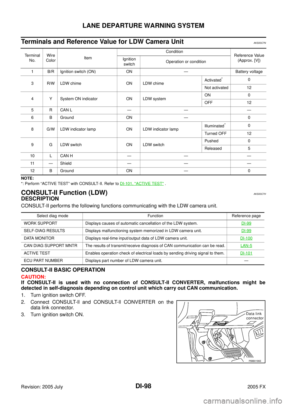
Terminals and Reference Value for LDW Camera UnitAKS00C7N
NOTE:
*: Perform “ACTIVE TEST” with CONSULT-II. Refer to DI-101, "
ACTIVE TEST" .
CONSULT-II Function (LDW)AKS00C7H
DESCRIPTION
CONSULT-II performs the following functions communicating with the LDW camera unit.
CONSULT-II BASIC OPERATION
CAUTION:
If CONSULT-II is used with no connection of CONSULT-II CONVERTER, malfunctions might be
detected in self-diagnosis depending on control unit which carry out CAN communication.
1. Turn ignition switch OFF.
2. Connect CONSULT-ll and CONSULT-ll CONVERTER on the data link connector.
3. Turn ignition switch ON.
Te r m i n a l No. Wire
Color Item Condition
Reference Value
(Approx. [V])
Ignition
switch Operation or condition
1 B/R Ignition switch (ON) ON — Battery voltage
3 R/W LDW chime ON LDW chime Activated
*0
Not activated 12
4 Y System ON indicator ON LDW system ON 0
OFF 12
5 R CAN L — — —
6 B Ground ON — 0
8 G/W LDW indicator lamp ON LDW indicator lamp Illuminated
*0
Turned OFF 12
9 G LDW switch ON LDW switch Pushed 0
Released 5
10 L CAN H — — — 11 — Shield — — —
12 B Ground ON — 0
Select diag mode Function Reference page
WORK SUPPORT Displays causes of automatic cancellation of the LDW system. DI-99
SELF-DIAG RESULTS Displays malfunctioning system memorized in LDW camera unit.DI-99
DATA MONITOR Displays real-time input/output data of LDW camera unit.DI-100
CAN DIAG SUPPORT MNTR The results of transmit/receive diagnosis of CAN communication can be read. LAN-5
ACTIVE TEST Enables operation check of electrical loads by sending driving signal to them.DI-101
ECU PART NUMBER Displays part number of LDW camera unit. —
PBIB0196E
Page 1360 of 4731

LANE DEPARTURE WARNING SYSTEM DI-99
C
D E
F
G H
I
J
L
M A
B
DI
Revision: 2005 July 2005 FX
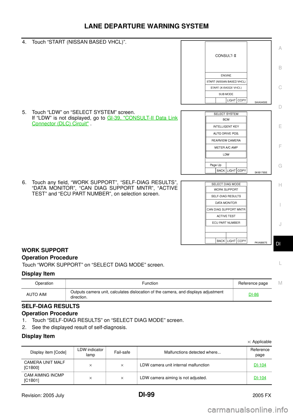
4. Touch “START (NISSAN BASED VHCL)”.
5. Touch “LDW” on “SELECT SYSTEM” screen.
If “LDW” is not displayed, go to GI-39, "
CONSULT-II Data Link
Connector (DLC) Circuit" .
6. Touch any field, “WORK SUPPORT”, “SELF-DIAG RESULTS”, “DATA MONITOR”, “CAN DIAG SUPPORT MNTR”, “ACTIVE
TEST” and “ECU PART NUMBER”, on selection screen.
WORK SUPPORT
Operation Procedure
Touch “WORK SUPPORT” on “SELECT DIAG MODE” screen.
Display Item
SELF-DIAG RESULTS
Operation Procedure
1. Touch “SELF-DIAG RESULTS” on “SELECT DIAG MODE” screen.
2. See the displayed result of self-diagnosis.
Display Item
× : Applicable
SAIA0450E
SKIB1785E
PKIA8867E
Operation Function Reference page
AUTO AIM Outputs camera unit, calculates dislocation of the camera, and displays adjustment
direction.
DI-86
Display item [Code] LDW indicator
lamp Fail-safe Malfunctions detected where...
Reference
page
CAMERA UNIT MALF
[C1B00] ××
LDW camera unit internal malfunction DI-104
CAM AIMING INCMP
[C1B01] ××
LDW camera aiming is not adjusted. DI-104
Page 1382 of 4731

REAR VIEW MONITOR DI-121
C
D E
F
G H
I
J
L
M A
B
DI
Revision: 2005 July 2005 FX
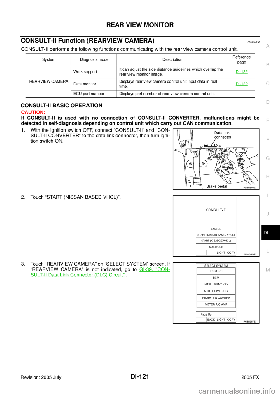
CONSULT-II Function (REARVIEW CAMERA)AKS007FM
CONSULT-II performs the following functions communicating with the rear view camera control unit.
CONSULT-II BASIC OPERATION
CAUTION:
If CONSULT-II is used with no connection of CONSULT-II CONVERTER, malfunctions might be
detected in self-diagnosis depending on control unit which carry out CAN communication.
1. With the ignition switch OFF, connect “CONSULT-II” and “CON- SULT-II CONVERTER” to the data link connector, then turn igni-
tion switch ON.
2. Touch “START (NISSAN BASED VHCL)”.
3. Touch “REARVIEW CAMERA” on “SELECT SYSTEM” screen. If “REARVIEW CAMERA” is not indicated, go to GI-39, "
CON-
SULT-II Data Link Connector (DLC) Circuit" .
System Diagnosis mode Description Reference
page
REARVIEW CAMERA Work support
It can adjust the side distance guidelines which overlap the
rear view monitor image. DI-122
Data monitor Displays rear view camera control unit input data in real
time. DI-122
ECU part number Displays part number of rear view camera control unit. —
PBIB1503E
SAIA0450E
PKIB1957E