Page 3968 of 4731

FRONT FOG LAMP LT-79
C
D E
F
G H
I
J
L
M A
B
LT
Revision: 2005 July 2005 FX
FRONT FOG LAMPPFP:26150
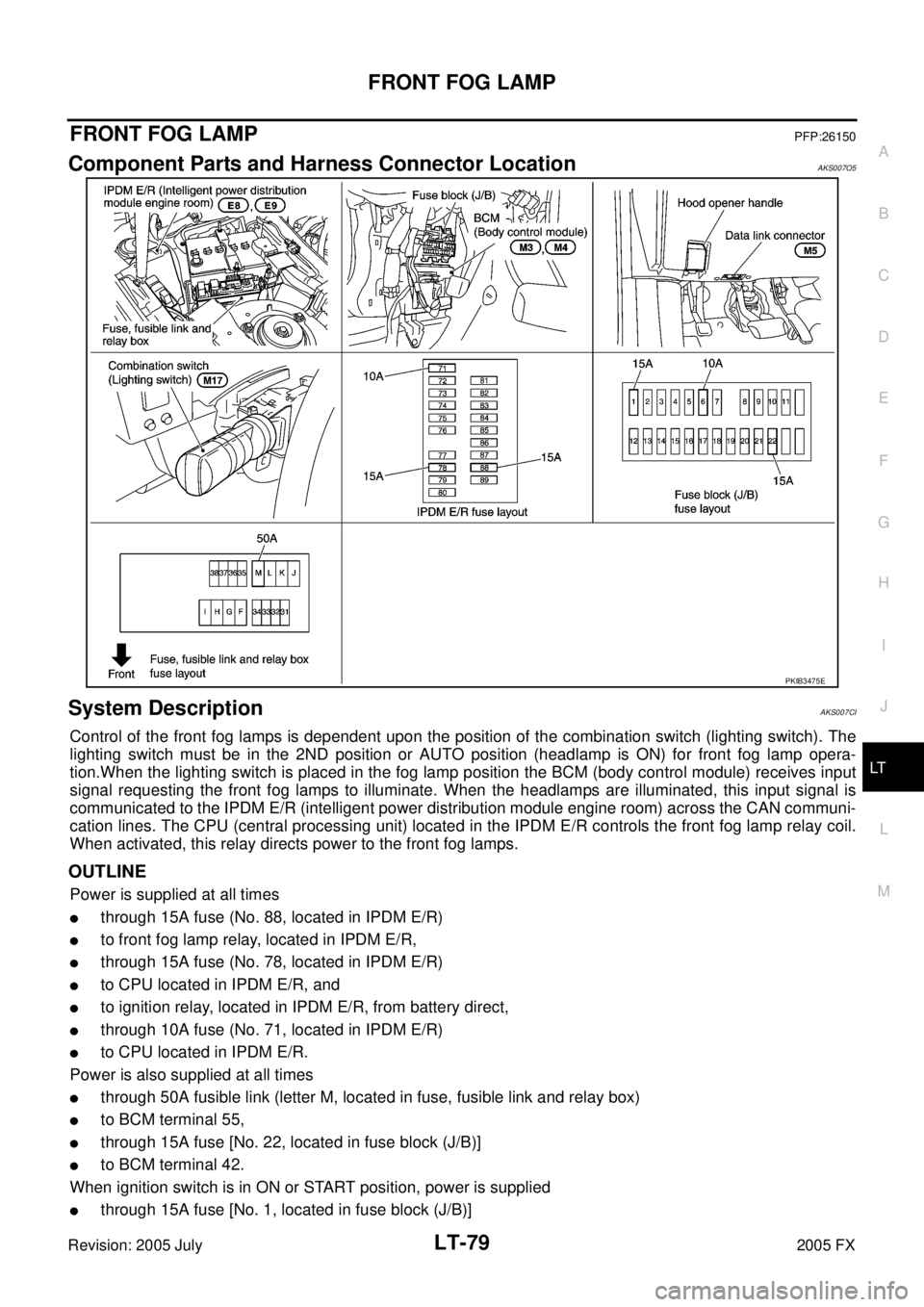
Component Parts and Harness Connector LocationAKS007O5
System DescriptionAKS007CI
Control of the front fog lamps is dependent upon the position of the combination switch (lighting switch). The
lighting switch must be in the 2ND position or AUTO position (headlamp is ON) for front fog lamp opera-
tion.When the lighting switch is placed in the fog lamp position the BCM (body control module) receives input
signal requesting the front fog lamps to illuminate. When the headlamps are illuminated, this input signal is
communicated to the IPDM E/R (intelligent power distribution module engine room) across the CAN communi-
cation lines. The CPU (central processing unit) located in the IPDM E/R controls the front fog lamp relay coil.
When activated, this relay directs power to the front fog lamps.
OUTLINE
Power is supplied at all times
�through 15A fuse (No. 88, located in IPDM E/R)
�to front fog lamp relay, located in IPDM E/R,
�through 15A fuse (No. 78, located in IPDM E/R)
�to CPU located in IPDM E/R, and
�to ignition relay, located in IPDM E/R, from battery direct,
�through 10A fuse (No. 71, located in IPDM E/R)
�to CPU located in IPDM E/R.
Power is also supplied at all times
�through 50A fusible link (letter M, located in fuse, fusible link and relay box)
�to BCM terminal 55,
�through 15A fuse [No. 22, located in fuse block (J/B)]
�to BCM terminal 42.
When ignition switch is in ON or START position, power is supplied
�through 15A fuse [No. 1, located in fuse block (J/B)]
PKIB3475E
Page 4357 of 4731

RF-18
SUNROOF
Revision: 2005 July 2005 FX
Trouble Diagnosis Chart by SymptomAIS003D0
Power Supply and Ground Circuit Check of BCMAIS003D1
1. CHECK FUSE
�Check 15A fuse [No.1, located in the fuse block (J/B)]
�Check 15A fuse [No.22, located in the fuse block (J/B)]
�Check 50A fusible link (letter M, located in the fuse and fusible link box).
NOTE:
Refer to RF-10, "
Component Parts and Harness Connector Location" .
OK or NG
OK >> GO TO 2.
NG >> If fuse is blown out, be sure to eliminate cause of malfunction before installing new fuse. Refer to RF-10, "
Component Parts and Harness Connector Location" .
2. CHECK POWER SUPPLY CIRCUIT
1. Turn ignition switch ON.
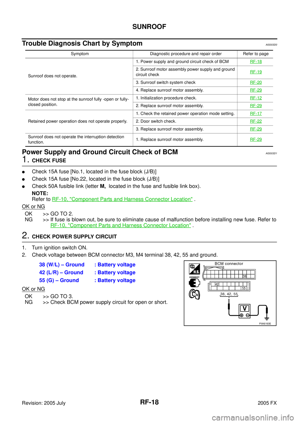
2. Check voltage between BCM connector M3, M4 terminal 38, 42, 55 and ground.
OK or NG
OK >> GO TO 3.
NG >> Check BCM power supply circuit for open or short.
Symptom Diagnostic procedure and repair order Refer to page
Sunroof does not operate. 1. Power supply and ground circuit check of BCM
RF-18
2. Sunroof motor assembly power supply and ground
circuit check RF-19
3. Sunroof switch system check
RF-20
4. Replace sunroof motor assembly.RF-29
Motor does not stop at the sunroof fully -open or fully-
closed position. 1. Initialization procedure check.
RF-12
2. Replace sunroof motor assembly.RF-29
Retained power operation does not operate properly. 1. Check the retained power operation mode setting.
RF-172. Door switch check.RF-22
3. Replace sunroof motor assembly.RF-29
Sunroof does not operate the interruption detection
function. 1. Replace sunroof motor assembly.
RF-29
38 (W/L) – Ground : Battery voltage
42 (L/R) – Ground : Battery voltage
55 (G) – Ground : Battery voltage
PIIA6160E
Page 4509 of 4731

SE-36
AUTOMATIC DRIVE POSITIONER
Revision: 2005 July 2005 FX
CHECK POWER SUPPLY AND GROUND
1. CHECK FUSE
Check if any of the following fuses in the BCM are blown.
�Check 50A fusible link (letter M , located in the fuse and fusible link box.)
�Check 15A fuse [No.22, located in the fuse block (J/B)]
�Check 10A fuse [No.1, located in the fuse block (J/B)]
�Check 10A fuse [No.6, located in the fuse block (J/B)]
NOTE:
Refer to SE-15, "
Component Parts and Harness Connector Location" .
OK or NG
OK >> GO TO 2.
NG >> If fuse is blown out, be sure to eliminate cause of malfunction before installing new fuse. Refer to
SE-15, "
Component Parts and Harness Connector Location" .
2. CHECK POWER SUPPLY CIRCUIT (BCM)
1. Turn ignition switch OFF.
2. Disconnect BCM connector.
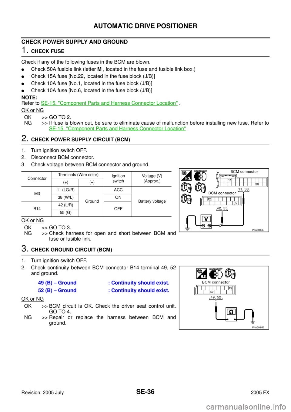
3. Check voltage between BCM connector and ground.
OK or NG
OK >> GO TO 3.
NG >> Check harness for open and short between BCM and fuse or fusible link.
3. CHECK GROUND CIRCUIT (BCM)
1. Turn ignition switch OFF.
2. Check continuity between BCM connector B14 terminal 49, 52 and ground.
OK or NG
OK >> BCM circuit is OK. Check the driver seat control unit. GO TO 4.
NG >> Repair or replace the harness between BCM and ground.
Connector Terminals (Wire color)
Ignition
switch Voltage (V)
(Approx.)
(+) (–)
M3 11 (LG/R)
Ground ACC
Battery voltage
38 (W/L) ON
B14 42 (L/R)
OFF
55 (G)
PIIA5083E
49 (B) – Ground : Continuity should exist.
52 (B) – Ground : Continuity should exist.
PIIA5084E