Page 1053 of 4731

BL-238
BODY REPAIR
Revision: 2005 July2005 FX
BODY REPAIRPFP:60100
Body Exterior Paint ColorAIS0034Q
2S:Solid + Clear, PM:Pearl + Metallic, M:Metallic, 3M:3-Coat Metallic, 2P:2-Coat pearl, 3P:3-Coat pearl, RPM:Multi flex color,
SIIA2248E
ComponentColor code BBW9 BC16 BEY0 BK25 BKH3 BKY0 BQX1 BR12 BWV2
DescriptionDark
BlueGray-
ish
BrownLight
GoldSilver Black Silver WhiteBrown-
ish
OrangeSilver
Paint type 2P PM RPM 3M 2S M 3P M M
Hard clear coat´´--´-- - -
1Bumper
fasciaBody color BBW9 BC16 BEY0 BK25 BKH3 BKY0 BQX1 BR12 BWV2
2Bumper
finisherBlack G01-1 G01-1 G01-1 G01-1 G01-1 G01-1 G01-1 G01-1 G01-1
3 Front grilleChromium-
plate + Color
clear coatCr2p Cr2p Cr2p Cr2p Cr2p Cr2p Cr2p Cr2p Cr2p
4Door out-
side
mirrorHous-
ingBody color BBW9 BC16 BEY0 BK25 BKH3 BKY0 BQX1 BR12 BWV2
Base Black G01-2 G01-2 G01-2 G01-2 G01-2 G01-2 G01-2 G01-2 G01-2
5Door out-
side han-
dleChromium-
plateCr2p Cr2p Cr2p Cr2p Cr2p Cr2p Cr2p Cr2p Cr2p
6Fuel filler
lidBody color BBW9 BC16 BEY0 BK25 BKH3 BKY0 BQX1 BR12 BWV2
7Rear
spoilerBody color BBW9 BC16 BEY0 BK25 BKH3 BKY0 BQX1 BR12 BWV2
8 Back door Body color BBW9 BC16 BEY0 BK25 BKH3 BKY0 BQX1 BR12 BWV2
Page 1112 of 4731
 “AIR BAG” and “SEAT
BELT PRE-TENSI")
PRECAUTIONS BR-3
C
D E
G H
I
J
K L
M A
B
BR
Revision: 2005 July 2005 FX
PRECAUTIONSPFP:00001
Precautions for Supplemental Restraint System (SRS) “AIR BAG” and “SEAT
BELT PRE-TENSIONER”
AFS0028A
The Supplemental Restraint System such as “AIR BAG” and “SEAT BELT PRE-TENSIONER”, used along
with a front seat belt, helps to reduce the risk or severity of injury to the driver and front passenger for certain
types of collision. This system includes seat belt switch inputs and dual stage front air bag modules. The SRS
system uses the seat belt switches to determine the front air bag deployment, and may only deploy one front
air bag, depending on the severity of a collision and whether the front occupants are belted or unbelted.
Information necessary to service the system safely is included in the SRS and SB section of this Service Man-
ual.
WARNING:
�To avoid rendering the SRS inoperative, which could increase the risk of personal injury or death
in the event of a collision which would result in air bag inflation, all maintenance must be per-
formed by an authorized NISSAN/INFINITI dealer.
�Improper maintenance, including incorrect removal and installation of the SRS, can lead to per-
sonal injury caused by unintentional activation of the system. For removal of Spiral Cable and Air
Bag Module, see the SRS section.
�Do not use electrical test equipment on any circuit related to the SRS unless instructed to in this
Service Manual. SRS wiring harnesses can be identified by yellow and/or orange harnesses or
harness connectors.
Precautions for Procedures without Cowl Top CoverAFS0038B
When performing the procedure after removing cowl top cover, cover
the lower end of windshield with urethane, etc.
Precautions for Brake SystemAFS001MQ
�Recommended fluid is brake fluid “DOT 3”.
�Do not reuse drained brake fluid.
�Be careful not to splash brake fluid on painted areas.
�To clean or wash all parts of master cylinder, disc brake caliper and wheel cylinder, use clean brake fluid.
�Do not use mineral oils such as gasoline or kerosene. They will ruin rubber parts of the hydraulic system.
�Use flare nut wrench when removing and installing brake tube.
�When installing brake piping, be sure to check torque.
�Before working, turn ignition switch OFF and disconnect con-
nectors for ABS actuator and electric unit (control unit) or battery
terminal.
�Burnish the brake contact surfaces after refinishing or replacing
drums or rotors, after replacing pads or linings, or if a soft pedal
occurs at very low mileage.
Refer to BR-25, "
BRAKE BURNISHING PROCEDURE" .
WARNING:
�Clean brake pads and shoes with a waste cloth, then wipe
with a dust collector.
PIIB3706J
SBR686C
Page 1123 of 4731
BR-14
BRAKE MASTER CYLINDER
Revision: 2005 July 2005 FX
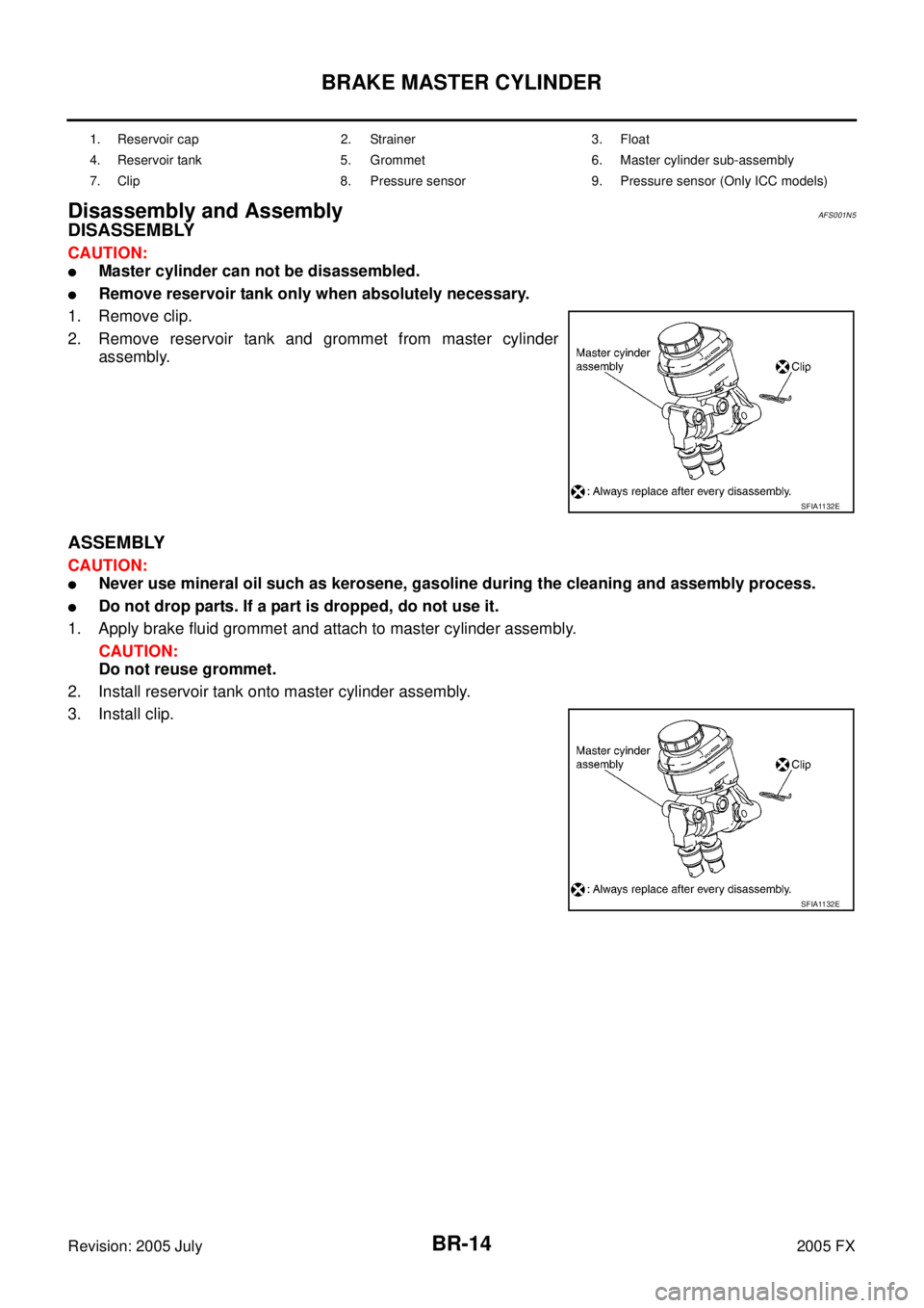
Disassembly and AssemblyAFS001N5
DISASSEMBLY
CAUTION:
�Master cylinder can not be disassembled.
�Remove reservoir tank only when absolutely necessary.
1. Remove clip.
2. Remove reservoir tank and grommet from master cylinder assembly.
ASSEMBLY
CAUTION:
�Never use mineral oil such as kerosene, gasoline during the cleaning and assembly process.
�Do not drop parts. If a part is dropped, do not use it.
1. Apply brake fluid grommet and attach to master cylinder assembly. CAUTION:
Do not reuse grommet.
2. Install reservoir tank onto master cylinder assembly.
3. Install clip.
1. Reservoir cap 2. Strainer 3. Float
4. Reservoir tank 5. Grommet 6. Master cylinder sub-assembly
7. Clip 8. Pressure sensor 9. Pressure sensor (Only ICC models)
SFIA1132E
SFIA1132E
Page 1127 of 4731
BR-18
VACUUM LINES
Revision: 2005 July 2005 FX
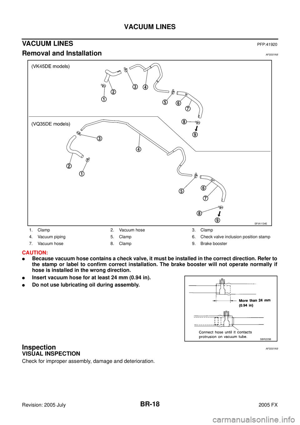
VACUUM LINESPFP:41920
Removal and InstallationAFS001N8
CAUTION:
�Because vacuum hose contains a check valve, it must be installed in the correct direction. Refer to
the stamp or label to confirm correct installation. The brake booster will not operate normally if
hose is installed in the wrong direction.
�Insert vacuum hose for at least 24 mm (0.94 in).
�Do not use lubricating oil during assembly.
InspectionAFS001N9
VISUAL INSPECTION
Check for improper assembly, damage and deterioration.
1. Clamp 2. Vacuum hose 3. Clamp
4. Vacuum piping 5. Clamp 6. Check valve inclusion position stamp
7. Vacuum hose 8. Clamp 9. Brake booster
SFIA1134E
SBR225B
Page 1131 of 4731

BR-22
FRONT DISC BRAKE
Revision: 2005 July 2005 FX
�Do not reuse drained brake fluid.
1. Install disc rotor.
2. Install caliper assembly to the vehicle, and tighten bolts to the specified torque.
CAUTION:
When attaching caliper assembly to the vehicle, wipe any
oil off knuckle spindle, washers and caliper assembly
attachment surfaces.
3. Install brake hose to brake caliper assembly, and tighten union bolt to the specified torque.
CAUTION:
�Do not reuse copper washers for union bolt.
�Attach brake hose to caliper assembly together with
union bolt and washers.
4. Refill new brake fluid and bleed air. Refer to BR-10, "
Bleeding Brake System" .
5. Attach tires to the vehicle.
Disassembly and Assembly of Brake Caliper AssemblyAFS001S1
DISASSEMBLY
1. Remove sliding pin bolt, and then remove the pad, shim, shim cover, and pad retainer from the torque member.
2. Remove sliding pins and sliding pin boots from torque member.
3. Place a wooden block as shown in the figure, and blow air from union bolt mounting hole to remove pistons and piston boots.
CAUTION:
Do not get your fingers caught in piston.
SFIA1205E
SFIA1204E
MAA0272D
Page 1132 of 4731

FRONT DISC BRAKE BR-23
C
D E
G H
I
J
K L
M A
B
BR
Revision: 2005 July 2005 FX
4. Using a flat-bladed screwdriver, remove piston seal from cylin-
der body.
CAUTION:
Be careful not to damage cylinder inner wall.
CALIPER INSPECTION
Cylinder Body
CAUTION:
�Use new brake fluid for cleaning. Do not use mineral oils such as gasoline or kerosene.
�Check inside surface of cylinder for score, rust, wear, damage or foreign materials. If any of the
above conditions are observed, replace cylinder body.
�Minor damage from rust or foreign materials may be eliminated by polishing surface with a fine
emery paper. Replace cylinder body if necessary.
To r q u e M e m b e r
Check for wear, cracks, and damage. If damage or deformation is present, replace the affected part.
Piston
Check piston for score, rust, wear, damage or presence of foreign materials. Replace if any of the above con-
dition are observed.
CAUTION:
Piston sliding surface is plated, do not polish with emery paper even if rust of foreign materials are
stuck to sliding surface.
Sliding Pins and Sliding Pin Boots
Check sliding pin and sliding pin boot for wear, damage, and cracks. If damage or deformation is present,
replace the affected part.
ASSEMBLY
CAUTION:
When assembling, use only rubber lubricant specified below.
1. Apply polyglycol ether based lubricant to the piston seal, and install them to the cylinder body.
SFIA0999E
SFIA2278E
Page 1137 of 4731

BR-28
REAR DISC BRAKE
Revision: 2005 July 2005 FX
INSTALLATION
CAUTION:
�Refill with new brake fluid “DOT 3”.
�Do not reuse drained brake fluid.
1. Install disc rotor.
2. Install caliper assembly to the vehicle, and tighten bolts to the specified torque. CAUTION:
Before installing caliper assembly to the vehicle, wipe off oil and grease on washer seats on axle
assembly and mounting surface of caliper assembly.
3. Install brake hose to caliper assembly and tighten union bolt to the specified torque.
CAUTION:
�Do not reuse copper washer for union bolt.
�Securely attach brake hose to protrusion on caliper assembly.
4. Refill new brake fluid and bleed air. Refer to BR-10, "
Bleeding Brake System" .
5. Install tires to the vehicle.
Disassembly and Assembly of Brake Caliper AssemblyAFS001NE
DISASSEMBLY
1. Remove sliding pin bolt, and then remove pad, shim, shim cover, and pad retainer from torque member and cylinder.
2. Remove sliding pin boot from torque member.
3. As shown in the figure, using a flat-bladed screwdriver, remove retaining ring from cylinder body.
4. Place a wooden block as shown in the figure, and blow air from union bolt mounting hole to remove pistons and piston boots.
CAUTION:
Do not get your fingers caught in piston.
5. Using a flat-bladed screwdriver, remove piston seals from cylin- der body.
CAUTION:
Be careful not to damage cylinder inner wall.
SBR028A
BRD0041D
SFIA0999E
Page 1138 of 4731

REAR DISC BRAKE BR-29
C
D E
G H
I
J
K L
M A
B
BR
Revision: 2005 July 2005 FX
CALIPER INSPECTION
Cylinder Body
CAUTION:
�Use new brake fluid to clean. Do not use mineral oils such as gasoline or kerosene.
�Check inside surface of cylinder for score, rust wear, damage or foreign materials. If any of the
above conditions are observed, replace cylinder body.
�Minor damage from rust or foreign materials may be eliminated by polishing surface with a fine
emery paper. Replace cylinder body if necessary.
To r q u e M e m b e r
Check for wear, cracks, and damage. If damage or deformation is present, replace the affected part.
Piston
CAUTION:
�Piston sliding surface is plated, do not polish with emery paper even if rust of foreign materials
are stuck to sliding surface.
�Check piston for score, rust, wear, damage or presence of foreign materials. Replace if any of the
above condition are observed.
Sliding Pin Bolts and Sliding Pin Boots
Make sure there is no wear, damage, or cracks in sliding pin bolts and sliding pin boots, and if there are,
replace them.
ASSEMBLY
CAUTION:
When assembling, use only rubber lubricant specified below.
1. Apply polyglycol ether based lubricant to the piston seal, and install them to the cylinder body.
2. Apply brake fluid to piston rubber grease to piston boot, then install piston boot in to piston groove.
CAUTION:
Do not reuse piston boot.
3. Insert into cylinder body by hand and insert piston boot piston-side lip into piston groove. CAUTION:
Press piston evenly and vary the pressing point to prevent cylinder inner wall from being rubbed.
SFIA2278E
SFIA2279E