Page 1347 of 4731
DI-86
LANE DEPARTURE WARNING SYSTEM
Revision: 2005 July 2005 FX
Camera Aiming AdjustmentAKS00C7J
OUTLINE
Adjust the camera aiming every time the LDW camera unit is removed or installed.
CAUTION:
�Place the vehicle on the level ground when the camera aiming adjustment is operated.
�Follow the CONSULT-II when adjusting the camera aiming. (Camera aiming adjustment cannot be
operated without CONSULT-II.)
PREPARATION
�Keep all tires inflated to correct pressures. Adjust the tire pressure to the specified pressure value.
�There is no-load in vehicle. Check if coolant, engine oil are filled up to correct level and fuel tank is full.
�Shift the gear into “P” position and release the parking brake.
�Clean the windshield.
NOTE:
Do not place anything reflective on the upper surface of instrument panel.
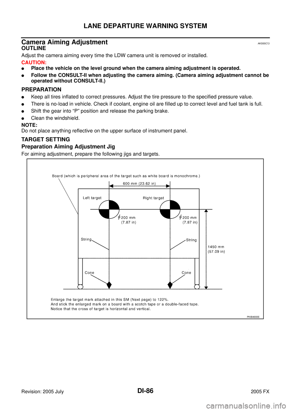
TARGET SETTING
Preparation Aiming Adjustment Jig
For aiming adjustment, prepare the following jigs and targets.
PKIB4693E
Page 1417 of 4731
![INFINITI FX35 2005 Service Manual EC-24
[VQ35DE]
PRECAUTIONS
Revision: 2005 July 2005 FX
�Do not disassemble ECM.
�If a battery cable is disconnected, the memory will return to
the ECM value.
The ECM will now start to self-control at](/manual-img/42/57020/w960_57020-1416.png "INFINITI FX35 2005 Service Manual EC-24
[VQ35DE]
PRECAUTIONS
Revision: 2005 July 2005 FX
�Do not disassemble ECM.
�If a battery cable is disconnected, the memory will return to
the ECM value.
The ECM will now start to self-control at")
EC-24
[VQ35DE]
PRECAUTIONS
Revision: 2005 July 2005 FX
�Do not disassemble ECM.
�If a battery cable is disconnected, the memory will return to
the ECM value.
The ECM will now start to self-control at its initial value.
Engine operation can vary slightly when the terminal is dis-
connected. However, this is not an indication of a malfunc-
tion. Do not replace parts because of a slight variation.
�If the battery is disconnected, the following emission-related diagnostic information will be lost
within 24 hours.
–Diagnostic trouble codes
–1st trip diagnostic trouble codes
–Freeze frame data
–1st trip freeze frame data
–System readiness test (SRT) codes
–Test values
�When connecting ECM harness connector, fasten it
securely with a lever as far as it will go as shown in the fig-
ure.
�When connecting or disconnecting pin connectors into or
from ECM, take care not to damage pin terminals (bend or
break).
Make sure that there are not any bends or breaks on ECM
pin terminal, when connecting pin connectors.
�Securely connect ECM harness connectors.
A poor connection can cause an extremely high (surge)
voltage to develop in coil and condenser, thus resulting in
damage to ICs.
�Keep engine control system harness at least 10 cm (4 in)
away from adjacent harness, to prevent engine control sys-
tem malfunctions due to receiving external noise, degraded
operation of ICs, etc.
�Keep engine control system parts and harness dry.
PBIB1164E
PBIB1512E
PBIB0090E
Page 1476 of 4731
BASIC SERVICE PROCEDURE EC-83
[VQ35DE]
C
D E
F
G H
I
J
K L
M A
EC
Revision: 2005 July 2005 FX
Idle Speed and Ignition Timing CheckABS006KC
IDLE SPEED
With CONSULT-II
Check idle speed in “DATA MONITOR” mode with CONSULT-II.
With GST
Check idle speed with Service $01 GST.
IGNITION TIMING
Any of following two methods may be used.
Method A
1. Attach timing light to loop wire as shown.
2. Check ignition timing.
Method B
1. Remove No. 1 ignition coil.
SEF058Y
PBIB1574E
PBIB1602E
PBIB1567E
Page 1477 of 4731
EC-84
[VQ35DE]
BASIC SERVICE PROCEDURE
Revision: 2005 July 2005 FX
2. Connect No. 1 ignition coil and No. 1 spark plug with suitable
high-tension wire as shown, and attach timing light clamp to this
wire.
3. Check ignition timing.
PBIB1573E
SEF166Y
PBIB1602E
Page 1478 of 4731
BASIC SERVICE PROCEDURE EC-85
[VQ35DE]
C
D E
F
G H
I
J
K L
M A
EC
Revision: 2005 July 2005 FX
Idle Mixture Ratio AdjustmentABS00E91
PREPARATION
1. Make sure that the following parts are in good order.
�Battery
�Ignition system
�Engine oil and coolant levels
�Fuses
�ECM harness connector
�Va c u u m h o s e s
�Air intake system
(Oil filler cap, oil level gauge, etc.)
�Fuel pressure
�Engine compression
�Throttle valve
�Evaporative emission system
2. On air conditioner equipped models, checks should be carried out while the air conditioner is OFF.
3. On automatic transmission equipped models, when checking idle rpm, ignition timing and mixture ratio, checks should be carried out while selector lever is in P or N position.
4. When measuring CO percentage, insert probe more than 40 cm (15.7 in) into tail pipe.
5. Turn OFF headlamp, heater blower, rear window defogger.
6. Keep front wheels pointed straight ahead.
Page 1503 of 4731
![INFINITI FX35 2005 Service Manual EC-110
[VQ35DE]
TROUBLE DIAGNOSIS
Revision: 2005 July 2005 FX
Symptom Matrix ChartABS006KS
SYSTEM — BASIC ENGINE CONTROL SYSTEM
SYMPTOM
Reference
page
HARD/NO START/RESTART (EXCP. HA)
ENGINE STA](/manual-img/42/57020/w960_57020-1502.png "INFINITI FX35 2005 Service Manual EC-110
[VQ35DE]
TROUBLE DIAGNOSIS
Revision: 2005 July 2005 FX
Symptom Matrix ChartABS006KS
SYSTEM — BASIC ENGINE CONTROL SYSTEM
SYMPTOM
Reference
page
HARD/NO START/RESTART (EXCP. HA)
ENGINE STA")
EC-110
[VQ35DE]
TROUBLE DIAGNOSIS
Revision: 2005 July 2005 FX
Symptom Matrix ChartABS006KS
SYSTEM — BASIC ENGINE CONTROL SYSTEM
SYMPTOM
Reference
page
HARD/NO START/RESTART (EXCP. HA)
ENGINE STALL
HESITATION/SURGING/FLAT SPOT
SPARK KNOCK/DETONATION
LACK OF POWER/POOR ACCELERATION
HIGH IDLE/LOW IDLE
ROUGH IDLE/HUNTING
IDLING VIBRATION
SLOW/NO RETURN TO IDLE
OVERHEATS/WATER TEMPERATURE HIGH
EXCESSIVE FUEL CONSUMPTION
EXCESSIVE OIL CONSUMPTION
BATTERY DEAD (UNDER CHARGE)
Warranty symptom code AA AB AC AD AE AF AG AH AJ AK AL AM HA
Fuel Fuel pump circuit 11232 22 3 2 EC-668
Fuel pressure regulator system334444444 4 EC-99
Injector circuit 11232 22 2 EC-661
Evaporative emission system 334444444 4EC-39
Air Positive crankcase ventilation sys-
tem 33 4444444 41
EC-51
Incorrect idle speed adjustment 1 1 1 1 1 EC-78
Electric throttle control actuator 112332222 2 2 EC-424,
EC-426
IgnitionIncorrect ignition timing adjustment33111 11 1 EC-78
Ignition circuit 11222 22 2EC-648
Power supply and ground circuit22333 33 23 EC-164
Mass air flow sensor circuit
1
12 2
222 2 EC-186,
EC-195
Engine coolant temperature sensor circuit
3 33
EC-208,
EC-220
Air fuel ratio (A/F) sensor EC-488
EC-497
EC-506
EC-516
EC-526
EC-536
EC-548
Throttle position sensor circuit
22 EC-213
,
EC-278
,
EC-479
,
EC-481
,
EC-633
Accelerator pedal position sensor circuit 3 2 1 EC-483
,
EC-619
,
EC-626
,
EC-640
Knock sensor circuit 2 3 EC-295
Crankshaft position sensor (POS) circuit 2 2EC-300
Camshaft position sensor (PHASE) circuit 3 2EC-307
Page 1504 of 4731
![INFINITI FX35 2005 Service Manual TROUBLE DIAGNOSIS EC-111
[VQ35DE]
C
D E
F
G H
I
J
K L
M A
EC
Revision: 2005 July 2005 FX
1 - 6: The numbers refer to the order of inspection.
(continued on next page) Vehicle speed sign](/manual-img/42/57020/w960_57020-1503.png "INFINITI FX35 2005 Service Manual TROUBLE DIAGNOSIS EC-111
[VQ35DE]
C
D E
F
G H
I
J
K L
M A
EC
Revision: 2005 July 2005 FX
1 - 6: The numbers refer to the order of inspection.
(continued on next page) Vehicle speed sign")
TROUBLE DIAGNOSIS EC-111
[VQ35DE]
C
D E
F
G H
I
J
K L
M A
EC
Revision: 2005 July 2005 FX
1 - 6: The numbers refer to the order of inspection.
(continued on next page) Vehicle speed signal circuit 2 3 3 3
EC-391
Power steering pressure sensor circuit 2 3 3EC-397
ECM 22333333333 EC-402,
EC-413
Intake valve timing control solenoid valve cir-
cuit 32 13223 3
EC-417
Park/neutral position (PNP) switch circuit 3 3 3 3 3 EC-609
Refrigerant pressure sensor circuit 2 3 3 4EC-674
Electrical load signal circuit 3EC-679
Air conditioner circuit223333333 3 2 AT C - 4 0
ABS actuator and electric unit (control unit) 4 BRC-12
SYMPTOM
Reference
page
HARD/NO START/RESTART (EXCP. HA)
ENGINE STALL
HESITATION/SURGING/FLAT SPOT
SPARK KNOCK/DETONATION
LACK OF POWER/POOR ACCELERATION
HIGH IDLE/LOW IDLE
ROUGH IDLE/HUNTING
IDLING VIBRATION
SLOW/NO RETURN TO IDLE
OVERHEATS/WATER TEMPERATURE HIGH
EXCESSIVE FUEL CONSUMPTION
EXCESSIVE OIL CONSUMPTION
BATTERY DEAD (UNDER CHARGE)
Warranty symptom code AA AB AC AD AE AF AG AH AJ AK AL AM HA
Page 1505 of 4731
![INFINITI FX35 2005 Service Manual EC-112
[VQ35DE]
TROUBLE DIAGNOSIS
Revision: 2005 July 2005 FX
SYSTEM — ENGINE MECHANICAL & OTHER
SYMPTOM
Reference
page
HARD/NO START/RESTART (EXCP. HA)
ENGINE STALL
HESITATION/SURGING/FLAT SPOT](/manual-img/42/57020/w960_57020-1504.png "INFINITI FX35 2005 Service Manual EC-112
[VQ35DE]
TROUBLE DIAGNOSIS
Revision: 2005 July 2005 FX
SYSTEM — ENGINE MECHANICAL & OTHER
SYMPTOM
Reference
page
HARD/NO START/RESTART (EXCP. HA)
ENGINE STALL
HESITATION/SURGING/FLAT SPOT")
EC-112
[VQ35DE]
TROUBLE DIAGNOSIS
Revision: 2005 July 2005 FX
SYSTEM — ENGINE MECHANICAL & OTHER
SYMPTOM
Reference
page
HARD/NO START/RESTART (EXCP. HA)
ENGINE STALL
HESITATION/SURGING/FLAT SPOT
SPARK KNOCK/DETONATION
LACK OF POWER/POOR ACCELERATION
HIGH IDLE/LOW IDLE
ROUGH IDLE/HUNTING
IDLING VIBRATION
SLOW/NO RETURN TO IDLE
OVERHEATS/WATER TEMPERATURE HIGH
EXCESSIVE FUEL CONSUMPTION
EXCESSIVE OIL CONSUMPTION
BATTERY DEAD (UNDER CHARGE)
Warranty symptom code AA AB AC AD AE AF AG AH AJ AK AL AM HA
Fuel Fuel tank 5
5 FL-10
Fuel piping 5 5 5 5 5 5
EM-45
Vapor lock —
Valve deposit 5 555 55 5 —
Poor fuel (Heavy weight gaso-
line, Low octane) —
Air Air duct
55555 5 EM-17
Air cleaner
EM-17
Air leakage from air duct
(Mass air flow sensor — electric
throttle control actuator) 5555 EM-17
Electric throttle control actuator
EM-19
Air leakage from intake manifold/
Collector/Gasket EM-19,
EM-24
Cranking Battery 111111
1 1
SC-4
Generator circuit
SC-23
Starter circuit 3SC-10
Signal plate 6EM-122
Park/neutral position (PNP)
switch 4
AT- 11 4
Engine Cylinder head
55555 55 5 EM-100
Cylinder head gasket 4 3
Cylinder block
66666 66 6 4
EM-122
Piston
Piston ring
Connecting rod
Bearing
Crankshaft
![INFINITI FX35 2005 Service Manual BASIC SERVICE PROCEDURE EC-83
[VQ35DE]
C
D E
F
G H
I
J
K L
M A
EC
Revision: 2005 July 2005 FX
Idle Speed and Ignition Timing CheckABS006KC
IDLE SPEED
With CONSULT-II
Check idle speed in](/manual-img/42/57020/w960_57020-1475.png "INFINITI FX35 2005 Service Manual BASIC SERVICE PROCEDURE EC-83
[VQ35DE]
C
D E
F
G H
I
J
K L
M A
EC
Revision: 2005 July 2005 FX
Idle Speed and Ignition Timing CheckABS006KC
IDLE SPEED
With CONSULT-II
Check idle speed in")
![INFINITI FX35 2005 Service Manual EC-84
[VQ35DE]
BASIC SERVICE PROCEDURE
Revision: 2005 July 2005 FX
2. Connect No. 1 ignition coil and No. 1 spark plug with suitable
high-tension wire as shown, and attach timing light clamp to this](/manual-img/42/57020/w960_57020-1476.png "INFINITI FX35 2005 Service Manual EC-84
[VQ35DE]
BASIC SERVICE PROCEDURE
Revision: 2005 July 2005 FX
2. Connect No. 1 ignition coil and No. 1 spark plug with suitable
high-tension wire as shown, and attach timing light clamp to this")
![INFINITI FX35 2005 Service Manual BASIC SERVICE PROCEDURE EC-85
[VQ35DE]
C
D E
F
G H
I
J
K L
M A
EC
Revision: 2005 July 2005 FX
Idle Mixture Ratio AdjustmentABS00E91
PREPARATION
1. Make sure that the following parts are i](/manual-img/42/57020/w960_57020-1477.png "INFINITI FX35 2005 Service Manual BASIC SERVICE PROCEDURE EC-85
[VQ35DE]
C
D E
F
G H
I
J
K L
M A
EC
Revision: 2005 July 2005 FX
Idle Mixture Ratio AdjustmentABS00E91
PREPARATION
1. Make sure that the following parts are i")