Page 3989 of 4731
LT-100
TURN SIGNAL AND HAZARD WARNING LAMPS
Revision: 2005 July 2005 FX
How to Proceed With Trouble DiagnosisAKS007D2
1. Confirm the symptom or customer complaint.
2. Understand operation description and function description. Refer to LT- 9 1 , "
System Description" .
3. Perform preliminary check. Refer to LT- 1 0 0 , "
Preliminary Check" .
4. Check symptom and repair or replace the cause of malfunction.
5. Do turn signal and hazard warning lamps operate normally? If YES, GO TO 6. If NO, GO TO 4.
6. INSPECTION END
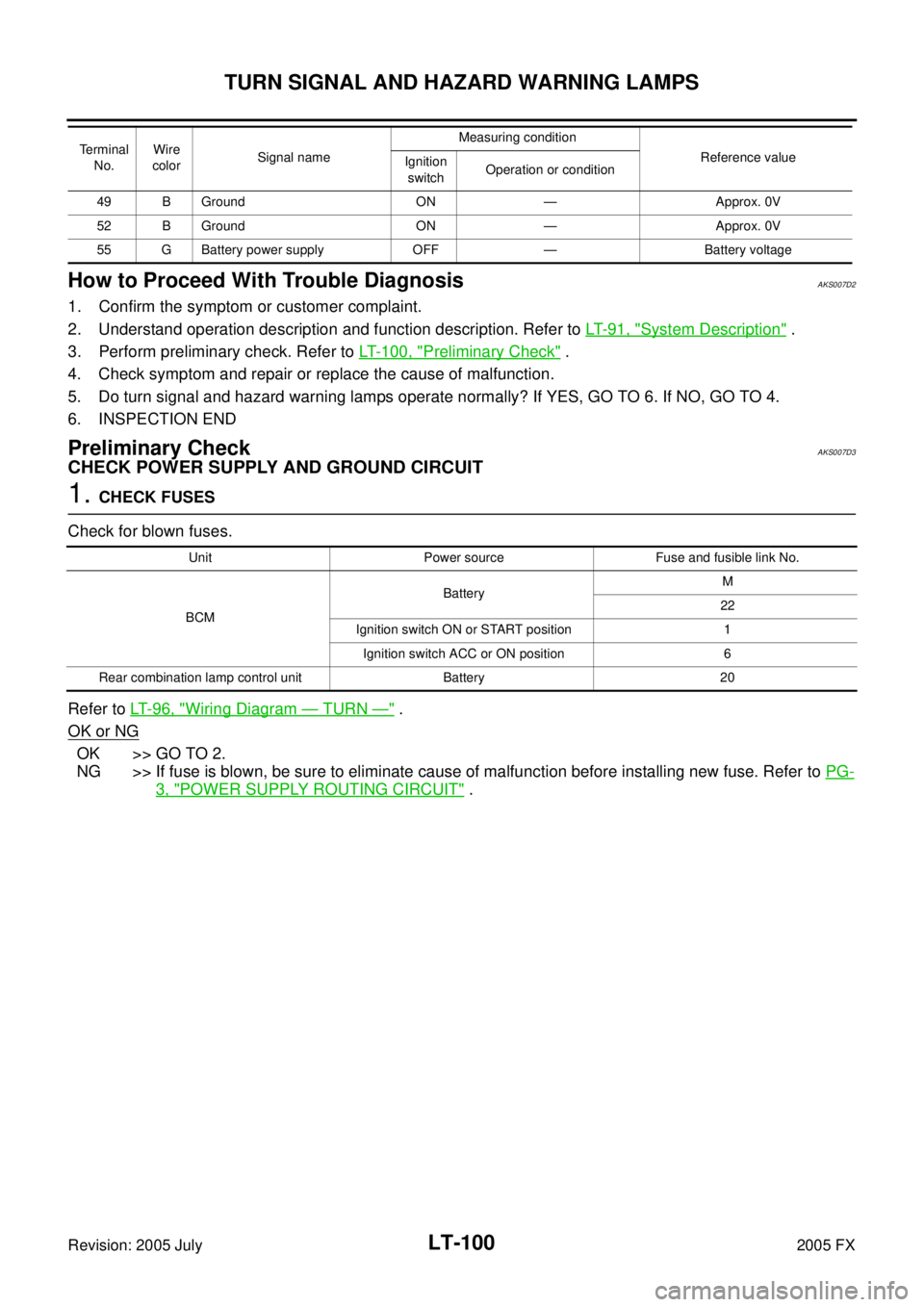
Preliminary CheckAKS007D3
CHECK POWER SUPPLY AND GROUND CIRCUIT
1. CHECK FUSES
Check for blown fuses.
Refer to LT- 9 6 , "
Wiring Diagram — TURN —" .
OK or NG
OK >> GO TO 2.
NG >> If fuse is blown, be sure to eliminate cause of malfunction before installing new fuse. Refer to PG-
3, "POWER SUPPLY ROUTING CIRCUIT" .
49 B Ground ON — Approx. 0V
52 B Ground ON — Approx. 0V
55 G Battery power supply OFF — Battery voltage
Terminal
No. Wire
color Signal name Measuring condition
Reference value
Ignition
switch Operation or condition
Unit Power source Fuse and fusible link No.
BCM Battery
M
22
Ignition switch ON or START position 1 Ignition switch ACC or ON position 6
Rear combination lamp control unit Battery 20
Page 3990 of 4731
TURN SIGNAL AND HAZARD WARNING LAMPS LT-101
C
D E
F
G H
I
J
L
M A
B
LT
Revision: 2005 July 2005 FX
2. CHECK POWER SUPPLY CIRCUIT
1. Turn ignition switch OFF.
2. Disconnect BCM connector.
3. Check voltage between BCM harness connector and ground.
OK or NG
OK >> GO TO 3.
NG >> Repair harness or connector.
3. CHECK GROUND CIRCUIT
Check continuity between BCM harness connector and ground.
OK or NG
OK >> INSPECTION END
NG >> Repair harness or connector.
Terminal Ignition switch position
(+) (-) OFF ACC ON
Connector Terminal
(Wire color)
M3 11 (LG/R)
Ground Approx. 0V
Battery
voltage Battery
voltage
38 (W/L) Approx. 0V Approx. 0V Battery
voltage
M4 42 (L/R)
Battery
voltage Battery
voltage Battery
voltage
55 (G) Battery
voltage Battery
voltage Battery
voltage
PKIB5197E
Terminal Continuity
Connector Terminal (Wire color) Ground Yes
M4 49 (B)
52 (B)
PKIB3545E
Page 3991 of 4731
LT-102
TURN SIGNAL AND HAZARD WARNING LAMPS
Revision: 2005 July 2005 FX
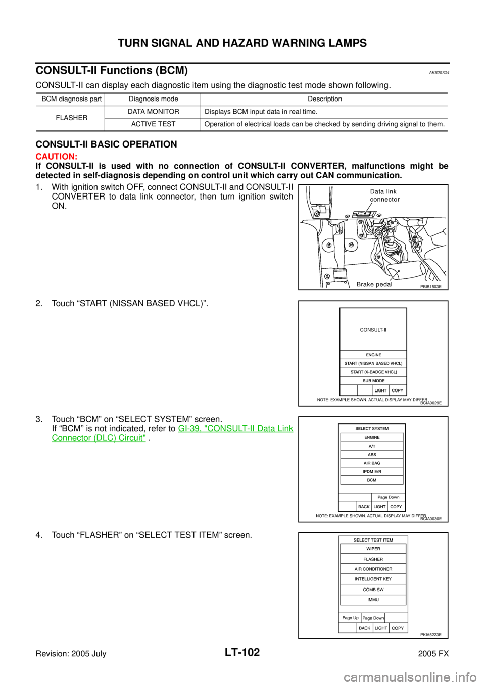
CONSULT-II Functions (BCM)AKS007D4
CONSULT-II can display each diagnostic item using the diagnostic test mode shown following.
CONSULT-II BASIC OPERATION
CAUTION:
If CONSULT-II is used with no connection of CONSULT-II CONVERTER, malfunctions might be
detected in self-diagnosis depending on control unit which carry out CAN communication.
1. With ignition switch OFF, connect CONSULT-II and CONSULT-II CONVERTER to data link connector, then turn ignition switch
ON.
2. Touch “START (NISSAN BASED VHCL)”.
3. Touch “BCM” on “SELECT SYSTEM” screen. If “BCM” is not indicated, refer to GI-39, "
CONSULT-II Data Link
Connector (DLC) Circuit" .
4. Touch “FLASHER” on “SELECT TEST ITEM” screen.
BCM diagnosis part Diagnosis mode Description FLASHER DATA MONITOR Displays BCM input data in real time.
ACTIVE TEST Operation of electrical loads can be checked by sending driving signal to them.
PBIB1503E
BCIA0029E
BCIA0030E
PKIA5223E
Page 3992 of 4731
TURN SIGNAL AND HAZARD WARNING LAMPS LT-103
C
D E
F
G H
I
J
L
M A
B
LT
Revision: 2005 July 2005 FX
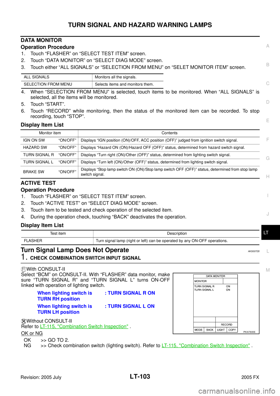
DATA MONITOR
Operation Procedure
1. Touch “FLASHER” on “SELECT TEST ITEM” screen.
2. Touch “DATA MONITOR” on “SELECT DIAG MODE” screen.
3. Touch either “ALL SIGNALS” or “SELECTION FROM MENU” on “SELET MONITOR ITEM” screen.
4. When “SELECTION FROM MENU” is selected, touch items to be monitored. When “ALL SIGNALS” is selected, all the items will be monitored.
5. Touch “START”.
6. Touch “RECORD” while monitoring, then the status of the monitored item can be recorded. To stop recording, touch “STOP”.
Display Item List
ACTIVE TEST
Operation Procedure
1. Touch “FLASHER” on “SELECT TEST ITEM” screen.
2. Touch “ACTIVE TEST” on “SELECT DIAG MODE” screen.
3. Touch item to be tested and check operation of the selected item.
4. During the operation check, touching “BACK” deactivates the operation.
Display Item List
Turn Signal Lamp Does Not OperateAKS007D5
1. CHECK COMBINATION SWITCH INPUT SIGNAL
With CONSULT-II
Select “BCM” on CONSULT-II. With “FLASHER” data monitor, make
sure “TURN SIGNAL R” and “TURN SIGNAL L” turns ON-OFF
linked with operation of lighting switch.
Without CONSULT-II
Refer to LT- 11 5 , "
Combination Switch Inspection" .
OK or NG
OK >> GO TO 2.
NG >> Check combination switch (lighting switch). Refer to LT- 11 5 , "
Combination Switch Inspection" .
ALL SIGNALS Monitors all the signals.
SELECTION FROM MENU Selects items and monitors them.
Monitor item Contents
IGN ON SW “ON/OFF” Displays “IGN position (ON)/OFF, ACC position (OFF)” judged from ignition switch signal.
HAZARD SW “ON/OFF” Displays “Hazard ON (ON)/Hazard OFF (OFF)” status, determined from hazard switch signal.
TURN SIGNAL R “ON/OFF” Displays “Turn right (ON)/Other (OFF)” status, determined from lighting switch signal.
TURN SIGNAL L “ON/OFF” Displays “Turn left (ON)/Other (OFF)” status, determined from lighting switch signal.
BRAKE SW “ON/OFF” Displays “Stop lamp switch ON (ON)/Stop lamp switch OFF (OFF)” status, determined from stop lamp
switch signal.
Test item Description
FLASHER Turn signal lamp (right or left) can be operated by any ON-OFF operations.
When lighting switch is
TURN RH position : TURN SIGNAL R ON
When lighting switch is
TURN LH position : TURN SIGNAL L ON
PKIA7600E
Page 3993 of 4731
LT-104
TURN SIGNAL AND HAZARD WARNING LAMPS
Revision: 2005 July 2005 FX
2. ACTIVE TEST
With CONSULT-II
1. Select “FLASHER” during active test. Refer to LT- 1 0 3 , "
ACTIVE
TEST" .
2. Make sure “FLASHER RIGHT” and “FLASHER LEFT” operate.
Without CONSULT-II
GO TO 3.
OK or NG
OK >> Replace BCM. Refer to BCS-16, "Removal and Installa-
tion of BCM" .
NG >> GO TO 3.
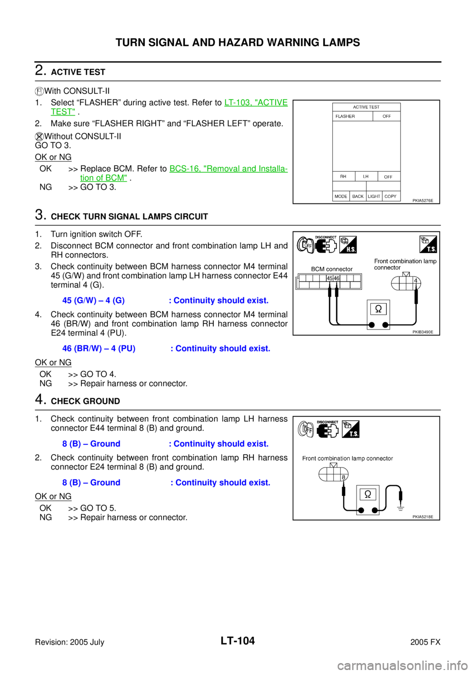
3. CHECK TURN SIGNAL LAMPS CIRCUIT
1. Turn ignition switch OFF.
2. Disconnect BCM connector and front combination lamp LH and RH connectors.
3. Check continuity between BCM harness connector M4 terminal 45 (G/W) and front combination lamp LH harness connector E44
terminal 4 (G).
4. Check continuity between BCM harness connector M4 terminal 46 (BR/W) and front combination lamp RH harness connector
E24 terminal 4 (PU).
OK or NG
OK >> GO TO 4.
NG >> Repair harness or connector.
4. CHECK GROUND
1. Check continuity between front combination lamp LH harness connector E44 terminal 8 (B) and ground.
2. Check continuity between front combination lamp RH harness connector E24 terminal 8 (B) and ground.
OK or NG
OK >> GO TO 5.
NG >> Repair harness or connector.
PKIA5276E
45 (G/W) – 4 (G) : Continuity should exist.
46 (BR/W) – 4 (PU) : Continuity should exist.
PKIB3490E
8 (B) – Ground : Continuity should exist.
8 (B) – Ground : Continuity should exist.
PKIA5218E
Page 3996 of 4731
TURN SIGNAL AND HAZARD WARNING LAMPS LT-107
C
D E
F
G H
I
J
L
M A
B
LT
Revision: 2005 July 2005 FX
Hazard Warning Lamp Does Not Operate But Turn Signal Lamp OperateAKS007D6
1. CHECK BULB
Make sure bulb standard of each turn signal lamp is correct.
OK or NG
OK >> GO TO 2.
NG >> Replace bulb.
2. CHECK HAZARD SWITCH INPUT SIGNAL
With CONSULT-II
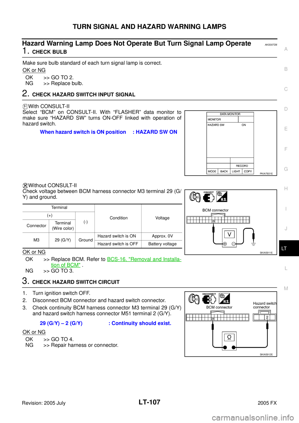
Select “BCM” on CONSULT-II. With “FLASHER” data monitor to
make sure “HAZARD SW” turns ON-OFF linked with operation of
hazard switch.
Without CONSULT-II
Check voltage between BCM harness connector M3 terminal 29 (G/
Y) and ground.
OK or NG
OK >> Replace BCM. Refer to BCS-16, "Removal and Installa-
tion of BCM" .
NG >> GO TO 3.
3. CHECK HAZARD SWITCH CIRCUIT
1. Turn ignition switch OFF.
2. Disconnect BCM connector and hazard switch connector.
3. Check continuity BCM harness connector M3 terminal 29 (G/Y) and hazard switch harness connector M51 terminal 2 (G/Y).
OK or NG
OK >> GO TO 4.
NG >> Repair harness or connector. When hazard switch is ON position : HAZARD SW ON
PKIA7601E
Terminal
Condition Voltage
(+)
(-)
Connector Te r m i n a l
(Wire color)
M3 29 (G/Y) Ground Hazard switch is ON Approx. 0V
Hazard switch is OFF Battery voltage
SKIA5911E
29 (G/Y) – 2 (G/Y) : Continuity should exist.
SKIA5912E
Page 4002 of 4731
COMBINATION SWITCH LT-113
C
D E
F
G H
I
J
L
M A
B
LT
Revision: 2005 July 2005 FX
Combination Switch Reading FunctionAKS007G5
For details, refer to BCS-3, "COMBINATION SWITCH READING FUNCTION" in "BCS" section.
CONSULT-II Functions (BCM)AKS007G6
�CONSULT-II can display each diagnostic item using the diagnostic test modes shown following.
CONSULT-II BASIC OPERATION
CAUTION:
If CONSULT-II is used with no connection of CONSULT-II CONVERTER, malfunctions might be
detected in self-diagnosis depending on control unit which carry out CAN communication.
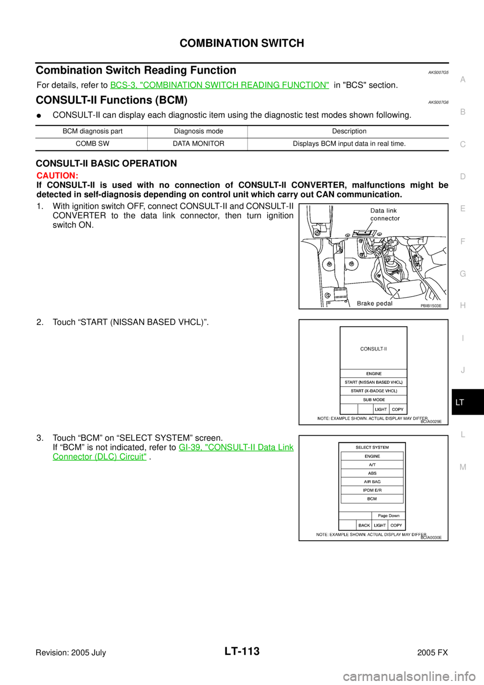
1. With ignition switch OFF, connect CONSULT-II and CONSULT-II CONVERTER to the data link connector, then turn ignition
switch ON.
2. Touch “START (NISSAN BASED VHCL)”.
3. Touch “BCM” on “SELECT SYSTEM” screen. If “BCM” is not indicated, refer to GI-39, "
CONSULT-II Data Link
Connector (DLC) Circuit" .
BCM diagnosis part Diagnosis mode Description
COMB SW DATA MONITOR Displays BCM input data in real time.
PBIB1503E
BCIA0029E
BCIA0030E
Page 4005 of 4731
LT-116
COMBINATION SWITCH
Revision: 2005 July 2005 FX
3. HARNESS INSPECTION
1. Turn ignition switch OFF.
2. Disconnect BCM and combination switch connectors.
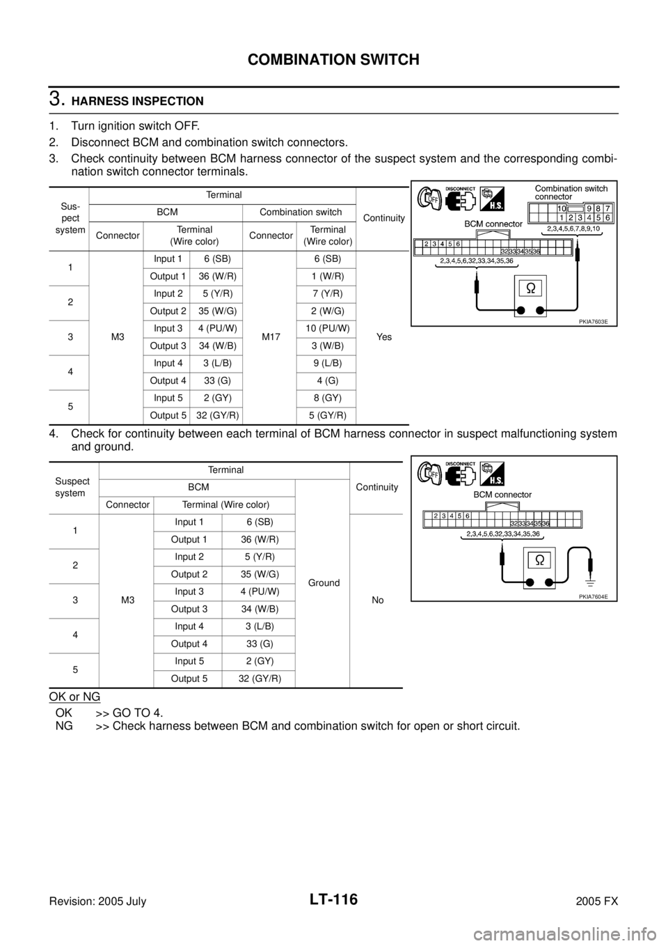
3. Check continuity between BCM harness connector of the suspect system and the corresponding combi- nation switch connector terminals.
4. Check for continuity between each terminal of BCM harness connector in suspect malfunctioning system and ground.
OK or NG
OK >> GO TO 4.
NG >> Check harness between BCM and combination switch for open or short circuit.
Sus-
pect
system Terminal
Continuity
BCM Combination switch
Connector Terminal
(Wire color) ConnectorTe r m i n a l
(Wire color)
1
M3 Input 1 6 (SB)
M17 6 (SB)
Ye s
Output 1 36 (W/R) 1 (W/R)
2 Input 2 5 (Y/R) 7 (Y/R)
Output 2 35 (W/G) 2 (W/G)
3 Input 3 4 (PU/W) 10 (PU/W)
Output 3 34 (W/B) 3 (W/B)
4 Input 4 3 (L/B) 9 (L/B)
Output 4 33 (G) 4 (G)
5 Input 5 2 (GY) 8 (GY)
Output 5 32 (GY/R) 5 (GY/R)
Suspect
system Terminal
Continuity
BCM
Ground
Connector Terminal (Wire color)
1
M3 Input 1 6 (SB)
No
Output 1 36 (W/R)
2 Input 2 5 (Y/R)
Output 2 35 (W/G)
3 Input 3 4 (PU/W)
Output 3 34 (W/B)
4 Input 4 3 (L/B)
Output 4 33 (G)
5 Input 5 2 (GY)
Output 5 32 (GY/R)
PKIA7603E
PKIA7604E