Page 965 of 4731

BL-150
INTELLIGENT KEY SYSTEM
Revision: 2005 July 2005 FX
Check Hazard FunctionAIS004NP
1. CHECK HAZARD WARNING LAMP
Does hazard warning lamp flash with hazard switch?
YES or NO
YES >> Hazard warning lamp circuit is OK.
NO >> Check hazard circuit. Refer to LT- 9 1 , "
TURN SIGNAL AND HAZARD WARNING LAMPS" .
Check Horn FunctionAIS004NQ
First perform the “SELF-DIAG RESULTS” in “BCM” with CONSULT-II, then perform the trouble diagnosis of
malfunction system indicated “SELF-DIAG RESULTS” of “BCM”. Refer to BCS-15, "
CAN Communication
Inspection Using CONSULT-II (Self-Diagnosis)" .
1. CHECK HORN FUNCTION
Does horn sound with horn switch?
YES or NO
YES >> Horn circuit is OK.
NO >> Check horn circuit. Refer to WW-59, "
HORN" .
Check Headlamp FunctionAIS004NR
First perform the “SELF-DIAG RESULTS” in “BCM” with CONSULT-II, then perform the trouble diagnosis of
malfunction system indicated “SELF-DIAG RESULTS” of “BCM”. Refer to BCS-15, "
CAN Communication
Inspection Using CONSULT-II (Self-Diagnosis)" .
1. CHECK HEADLAMP OPERATION
Does headlamp come on when turning lighting switch “ON”?
YES or NO
YES >> Headlamp operation circuit is OK.
NO >> Check headlamp system. Refer to LT- 7 , "
HEADLAMP - XENON TYPE -" .
Check IPDM E/R OperationAIS004NS
1. CHECK IPDM E/R INPUT VOLTAGE
Check voltage between IPDM E/R connector E9 terminal 51 (SB) and ground.
OK or NG
OK >> Replace IPDM E/R.
NG >> GO TO 2. 51 (SB) – Ground : Battery voltage
PIIA6403E
Page 967 of 4731
BL-152
INTELLIGENT KEY SYSTEM
Revision: 2005 July 2005 FX
Intelligent Key Battery ReplacementAIS006D5
INTELLIGENT KEY BATTERY INSPECTION
Check by connecting a resistance (approximately 300Ω) so that the
current value becomes about 10 mA.
PIIB4646E
Standard : Approx. 2.5V - 3.0V
OCC0607D
Page 989 of 4731
BL-174
BACK DOOR AUTO CLOSURE SYSTEM
Revision: 2005 July 2005 FX
Terminals and Reference Value for Back Door Closure Control UnitAIS004OG
*, (): Models with Intelligent Key Te r m i -
nal Wire
color Item Condition Voltage (V)
(Approx.)
1 R Power source (Fuse) — Battery voltage
2 PU Closure motor (open) signal Fully close → fully open
3 G Closure motor (close) signal Fully open → fully close
4 B Ground — 0
5 W
(B) Ground* — 0*
Unlock sensor signal
(passenger side) Passenger side door lock is locked 5
Passenger side door lock is unlocked 0
6 Y
(LG) Back door opener switch signal Back door opener switch is ON 0
Other than above 5
7 OR Half-latch switch signal Fully open → fully close
8 L Close switch signal Fully open → fully close
9 P Open switch signal Fully open → fully close
SIIA1480J
SIIA1480J
SIIA1479J
SIIA1478J
SIIA1481J
Page 991 of 4731

BL-176
BACK DOOR AUTO CLOSURE SYSTEM
Revision: 2005 July 2005 FX
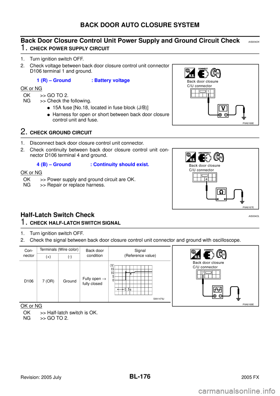
Back Door Closure Control Unit Power Supply and Ground Circuit CheckAIS004OK
1. CHECK POWER SUPPLY CIRCUIT
1. Turn ignition switch OFF.
2. Check voltage between back door closure control unit connector D106 terminal 1 and ground.
OK or NG
OK >> GO TO 2.
NG >> Check the following.
�15A fuse [No.18, located in fuse block (J/B)]
�Harness for open or short between back door closure
control unit and fuse.
2. CHECK GROUND CIRCUIT
1. Disconnect back door closure control unit connector.
2. Check continuity between back door closure control unit con- nector D106 terminal 4 and ground.
OK or NG
OK >> Power supply and ground circuit are OK.
NG >> Repair or replace harness.
Half-Latch Switch CheckAIS004OL
1. CHECK HALF-LATCH SWITCH SIGNAL
1. Turn ignition switch OFF.
2. Check the signal between back door closure control unit connector and ground with oscilloscope.
OK or NG
OK >> Half-latch switch is OK.
NG >> GO TO 2. 1 (R) – Ground : Battery voltage
PIIA6166E
4 (B) – Ground : Continuity should exist.
PIIA6167E
Con-
nector Terminals (Wire color)
Back door
condition Signal
(Reference value)
(+) (-)
D106 7 (OR) Ground Fully open
→
fully closed
PIIA6168E
SIIA1479J
Page 992 of 4731

BACK DOOR AUTO CLOSURE SYSTEM BL-177
C
D E
F
G H
J
K L
M A
B
BL
Revision: 2005 July 2005 FX
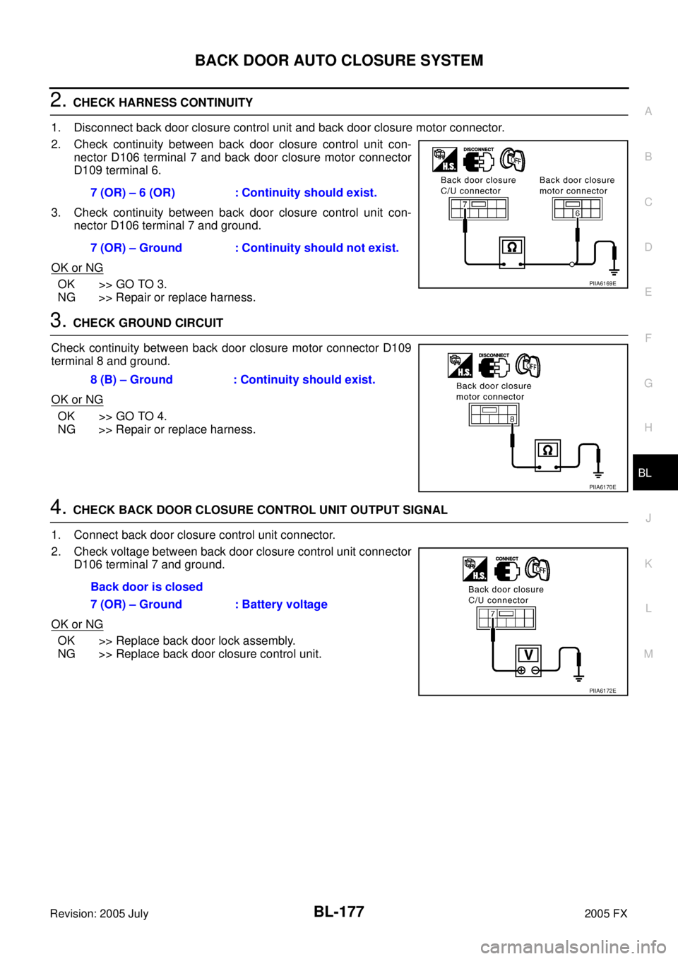
2. CHECK HARNESS CONTINUITY
1. Disconnect back door closure control unit and back door closure motor connector.
2. Check continuity between back door closure control unit con- nector D106 terminal 7 and back door closure motor connector
D109 terminal 6.
3. Check continuity between back door closure control unit con- nector D106 terminal 7 and ground.
OK or NG
OK >> GO TO 3.
NG >> Repair or replace harness.
3. CHECK GROUND CIRCUIT
Check continuity between back door closure motor connector D109
terminal 8 and ground.
OK or NG
OK >> GO TO 4.
NG >> Repair or replace harness.
4. CHECK BACK DOOR CLOSURE CONTROL UNIT OUTPUT SIGNAL
1. Connect back door closure control unit connector.
2. Check voltage between back door closure control unit connector D106 terminal 7 and ground.
OK or NG
OK >> Replace back door lock assembly.
NG >> Replace back door closure control unit. 7 (OR) – 6 (OR) : Continuity should exist.
7 (OR) – Ground : Continuity should not exist.
PIIA6169E
8 (B) – Ground : Continuity should exist.
PIIA6170E
Back door is closed
7 (OR) – Ground : Battery voltage
PIIA6172E
Page 994 of 4731

BACK DOOR AUTO CLOSURE SYSTEM BL-179
C
D E
F
G H
J
K L
M A
B
BL
Revision: 2005 July 2005 FX
4. CHECK BACK DOOR CLOSURE CONTROL UNIT OUTPUT SIGNAL
1. Connect back door closure control unit connector.
2. Check voltage between back door closure control unit connector D106 terminal 8 and ground.
OK or NG
OK >> Replace back door lock assembly.
NG >> Replace back door closure control unit.
Open Switch CheckAIS004ON
1. CHECK OPEN SWITCH SIGNAL
1. Turn ignition switch OFF.
2. Check the signal between back door closure control unit connector and ground with oscilloscope.
OK or NG
OK >> Open switch is OK.
NG >> GO TO 2.
2. CHECK HARNESS CONTINUITY
1. Disconnect back door closure control unit and back door closure motor connector.
2. Check continuity between back door closure control unit con- nector D106 terminal 9 and back door closure motor connector
D109 terminal 4.
3. Check continuity between back door closure control unit con- nector D106 terminal 9 and ground.
OK or NG
OK >> GO TO 3.
NG >> Repair or replace harness. Back door is closed
8 (L) – Ground : Battery voltage
PIIA6173E
Con-
nector Terminals (Wire color)
Back door
condition Signal
(Reference value)
(+) (-)
D106 9 (P) Ground Fully open
→
fully closed
PIIA6175E
SIIA1481J
9 (P) – 4 (P) : Continuity should exist.
9 (P) – Ground : Continuity should not exist.
PIIA6176E
Page 995 of 4731

BL-180
BACK DOOR AUTO CLOSURE SYSTEM
Revision: 2005 July 2005 FX
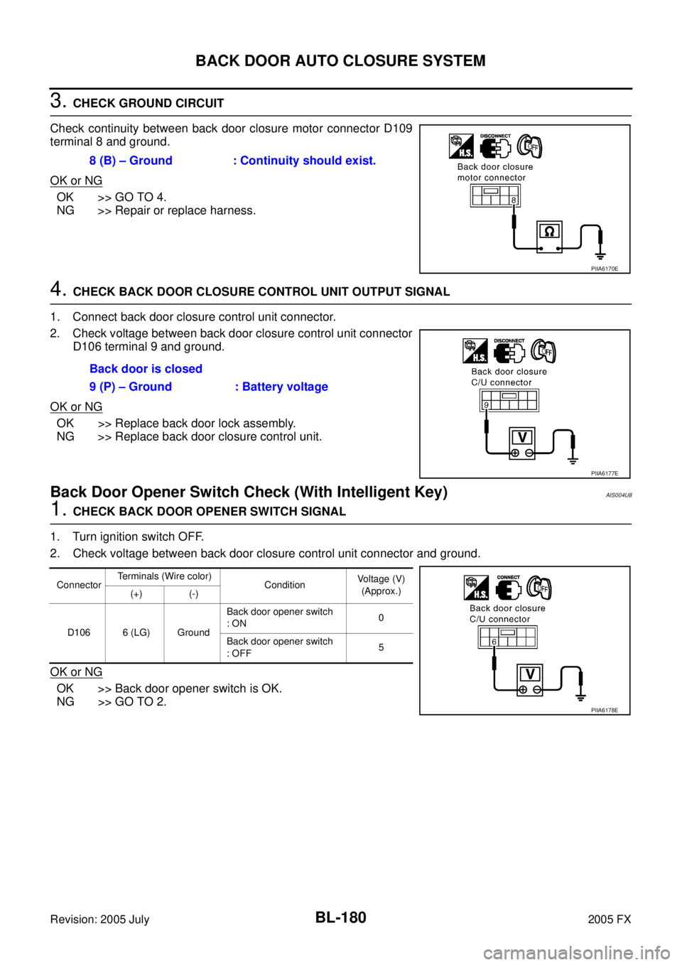
3. CHECK GROUND CIRCUIT
Check continuity between back door closure motor connector D109
terminal 8 and ground.
OK or NG
OK >> GO TO 4.
NG >> Repair or replace harness.
4. CHECK BACK DOOR CLOSURE CONTROL UNIT OUTPUT SIGNAL
1. Connect back door closure control unit connector.
2. Check voltage between back door closure control unit connector D106 terminal 9 and ground.
OK or NG
OK >> Replace back door lock assembly.
NG >> Replace back door closure control unit.
Back Door Opener Switch Check (With Intelligent Key)AIS004U8
1. CHECK BACK DOOR OPENER SWITCH SIGNAL
1. Turn ignition switch OFF.
2. Check voltage between back door closure control unit connector and ground.
OK or NG
OK >> Back door opener switch is OK.
NG >> GO TO 2. 8 (B) – Ground : Continuity should exist.
PIIA6170E
Back door is closed
9 (P) – Ground : Battery voltage
PIIA6177E
Connector Terminals (Wire color)
Condition Voltage (V)
(Approx.)
(+) (-)
D106 6 (LG) Ground Back door opener switch
: ON 0
Back door opener switch
: OFF 5
PIIA6178E
Page 1004 of 4731

VEHICLE SECURITY (THEFT WARNING) SYSTEM BL-189
C
D E
F
G H
J
K L
M A
B
BL
Revision: 2005 July 2005 FX
Canceling the Set Vehicle Security System
When one of the following operations is performed, the armed phase is canceled.
1. Unlock the doors with the key, key fob or Intelligent Key.
2. Turn ignition switch “ON” or “ACC” position.
Canceling the Alarm Operation of the Vehicle Security System
When unlock the door with the key, key fob or Intelligent Key the alarm operation is canceled.
Activating the Alarm Operation of the Vehicle Security System
Make sure the system is in the armed phase. (The security indicator lamp brinks every 2.4 seconds.)
When the following operation 1 or 2 is performed, the system sounds the horns and flashes the headlamps for
about 50 seconds.
1. Hood, back door or any door is opened during armed phase.
2. Disconnecting and connecting the battery connector before canceling armed phase.
POWER SUPPLY
Power is supplied at all times
�through 10A fuse [No.19, located in the fuse block (J/B)]
�to security indicator lamp terminal 1.
�through 50A fusible link (letter M , located in the fuse and fusible link box)
�to BCM terminal 55.
�through 15A fuse [No.22, located in the fuse block (J/B)]
�to BCM terminal 42.
�through 15A fuse [No.34, located in the fuse and fusible link box]
�to horn relay terminal 2.
�through 10A fuse [No.71, located in the IPDM E/R]
�to IPDM E/R internal CPU.
�through 15A fuse [No.78, located in the IPDM E/R]
�to IPDM E/R internal CPU.
With the ignition switch in the ACC or ON position, power is supplied
�through 10A fuse [No. 6, located in the fuse block (J/B)]
�to BCM terminal 11.
INITIAL CONDITION TO ACTIVATE THE SYSTEM
The operation of the vehicle security system is controlled by the doors, hood and back door.
To activate the vehicle security system, BCM must receive signals indicating the doors, hood and back door
are closed and the doors are locked by key fob, Intelligent Key or ignition key.
When a door is open, BCM terminal 12 (passenger side door), 13 (rear RH door), 62 (driver side door), 63
(rear LH door) receives a ground signal from each door switch.
When front door LH is unlocked by power window main switch (door lock and unlock switch),
BCM terminal 22 receives a signal from terminal 14 of power window main switch with power window serial
link.
When front door RH is unlocked by front power window switch (passenger side) (door lock and unlock switch),
BCM terminal 22 receives a signal from terminal 16 of front power window switch (passenger side) with power
window serial link.
When the hood is open, IPDM E/R receives a ground signal
�to IPDM E/R terminal 56
�through hood switch terminal 2
�through hood switch terminal 1
�through body grounds E21, E50 and E51.
The IPDM E/R then sends a signal to the BCM through the CAN SYSTEM.
When the back door is open,
�to BCM terminal 58
�through back door closure motor terminal 7