Page 2841 of 4731
![INFINITI FX35 2005 Service Manual EM-6
[VQ35DE]
PRECAUTIONS
Revision: 2005 July 2005 FX
Precautions for Assembly and InstallationABS00E3N
�Use torque wrench to tighten bolts or nuts to specification.
�When tightening nuts and bolts, a](/manual-img/42/57020/w960_57020-2840.png "INFINITI FX35 2005 Service Manual EM-6
[VQ35DE]
PRECAUTIONS
Revision: 2005 July 2005 FX
Precautions for Assembly and InstallationABS00E3N
�Use torque wrench to tighten bolts or nuts to specification.
�When tightening nuts and bolts, a")
EM-6
[VQ35DE]
PRECAUTIONS
Revision: 2005 July 2005 FX
Precautions for Assembly and InstallationABS00E3N
�Use torque wrench to tighten bolts or nuts to specification.
�When tightening nuts and bolts, as a basic rule, equally tighten in several different steps starting with the
ones in center, then ones on inside and outside diagonally in this order. If the order of tightening is speci-
fied, do exactly as specified.
�Replace with new gasket, packing, oil seal or O-ring.
�Thoroughly wash, clean, and air-blow each part. Carefully check engine oil or engine coolant passages for
any restriction and blockage.
�Avoid damaging sliding or mating surfaces. Completely remove foreign materials such as cloth lint or dust.
Before assembly, oil sliding surfaces well.
�Release air within route when refilling after draining engine coolant.
�After repairing, start the engine and increase engine speed to check engine coolant, fuel, engine oil, and
exhaust gases for leakage.
Precautions for Angle TighteningABS00E3O
�Use the angle wrench [SST: KV10112100 (BT8653-A)] for the final tightening of the following engine parts:
–Cylinder head bolts
–Main bearing cap bolts
–Connecting rod cap bolts
–Crankshaft pulley bolt (No the angle wrench is required as bolt flange is provided with notches for angle
tightening)
�Do not use a torque value for final tightening.
�The torque value for these parts are for a preliminary step.
�Ensure thread and seat surfaces are clean and coated with engine oil.
Precautions for Liquid GasketABS00E3P
REMOVAL OF LIQUID GASKET SEALING
�After removing mounting nuts and bolts, separate the mating
surface using the seal cutter [SST] and remove old liquid gasket
sealing.
CAUTION:
Be careful not to damage the mating surfaces.
�Tap the seal cutter to insert it, and then slide it by tapping on the
side as shown in the figure.
�In areas where the seal cutter is difficult to use, use a plastic
hammer to lightly tap the parts, to remove it.
CAUTION:
If for some unavoidable reason tool such as a screwdriver
is used, be careful not to damage the mating surfaces.
LIQUID GASKET APPLICATION PROCEDURE
1. Using a scraper, remove old liquid gasket adhering to the gasket application surface and the mating surface.
�Remove liquid gasket completely from the groove of the gas-
ket application surface, mounting bolts, and bolt holes.
2. Wipe the liquid gasket application surface and the mating sur- face with white gasoline (lighting and heating use) to remove
adhering moisture, grease and foreign materials.
PBIC0002E
PBIC0003E
Page 2851 of 4731
![INFINITI FX35 2005 Service Manual EM-16
[VQ35DE]
DRIVE BELTS
Revision: 2005 July 2005 FX
ALTERNATOR AND POWER STEERING OIL PUMP BELT
1. Remove front engine undercover with power tool.
2. Loosen idler pulley lock nut (A) and adjust te](/manual-img/42/57020/w960_57020-2850.png "INFINITI FX35 2005 Service Manual EM-16
[VQ35DE]
DRIVE BELTS
Revision: 2005 July 2005 FX
ALTERNATOR AND POWER STEERING OIL PUMP BELT
1. Remove front engine undercover with power tool.
2. Loosen idler pulley lock nut (A) and adjust te")
EM-16
[VQ35DE]
DRIVE BELTS
Revision: 2005 July 2005 FX
ALTERNATOR AND POWER STEERING OIL PUMP BELT
1. Remove front engine undercover with power tool.
2. Loosen idler pulley lock nut (A) and adjust tension by turning adjusting bolt (B).
�For the specified belt tension, refer to EM-15, "Checking Drive
Belts" .
3. Tighten nut (A).
A/C COMPRESSOR BELT
1. Remove front engine undercover with power tool.
2. Loosen idler pulley lock nut (C) and adjust tension by turning adjusting bolt (D).
�For the specified belt tension, refer to EM-15, "Checking Drive Belts" .
3. Tighten nut (C).
Removal and InstallationABS004TZ
REMOVAL
1. Remove front engine undercover with power tool.
2. Remove alternator and power steering oil pump belt. Refer to EM-16, "
ALTERNATOR AND POWER
STEERING OIL PUMP BELT" .
3. Remove A/C compressor belt. Refer to EM-16, "
A/C COMPRESSOR BELT" .
CAUTION:
Grease is applied to idler pulley adjusting bolt. Be careful to keep grease away from belt.
INSTALLATION
1. Install belts to pulley in reverse order of removal.
CAUTION:
�Make sure drive belt is correctly engaged with pulley groove.
�Make sure that for engine oil and engine coolant do not adhere to belt and each pulley grooves.
2. Adjust belt tension. Refer to EM-15, "
Tension Adjustment" .
3. Tighten each adjusting bolt and nut to the specified torque.
4. Make sure that tension of each belt is within the standard. Refer to EM-15, "
Checking Drive Belts" .
: 34.8 N·m (3.5 kg-m, 26 ft-lb)
SBIA0532E
: 34.8 N·m (3.5 kg-m, 26 ft-lb)
Page 2857 of 4731
![INFINITI FX35 2005 Service Manual EM-22
[VQ35DE]
INTAKE MANIFOLD COLLECTOR
Revision: 2005 July 2005 FX
INSTALLATION
Note the following, and install in the reverse order of removal.
Part Installation Direction
Referring to front marks,](/manual-img/42/57020/w960_57020-2856.png "INFINITI FX35 2005 Service Manual EM-22
[VQ35DE]
INTAKE MANIFOLD COLLECTOR
Revision: 2005 July 2005 FX
INSTALLATION
Note the following, and install in the reverse order of removal.
Part Installation Direction
Referring to front marks,")
EM-22
[VQ35DE]
INTAKE MANIFOLD COLLECTOR
Revision: 2005 July 2005 FX
INSTALLATION
Note the following, and install in the reverse order of removal.
Part Installation Direction
Referring to front marks, install parts shown in figure.
Intake Manifold Collector (Lower)
Tighten mounting bolts in numerical order as shown in the figure.
NOTE:
Tighten mounting bolts to secure gasket (lower), intake manifold col-
lector (lower), gasket (upper), and intake manifold collector cover.
Intake Manifold Collector (Upper)
�If stud bolts were removed, install them and tighten to the specified torque below.
�Shank length under bolt head varies with bolt location. Install
mounting bolts while referring to numbers shown below and in
the figure. (Bolt length does not include pilot portion.)
�Tighten mounting bolts in numerical order as shown in the fig-
ure.
Water Hose
�Insert hose by 27 to 32 mm (1.06 to 1.26 in) from connector end.
PBIC0776E
PBIC0774E
: 5.9 N·m (0.6 kg-m, 52 in-lb)
Bolt M6 × 25 mm (0.98 in) : 7, 8, 10, 11, 13, 14, 15, 16, 18
M6 × 45 mm (1.77 in) : 2, 4, 5
M6 × 60 mm (2.36 in) : 1, 3, 6, 9
M6 Nut : 12, 17
PBIC0773E
Page 2860 of 4731
INTAKE MANIFOLD EM-25
[VQ35DE]
C
D E
F
G H
I
J
K L
M A
EM
Revision: 2005 July 2005 FX
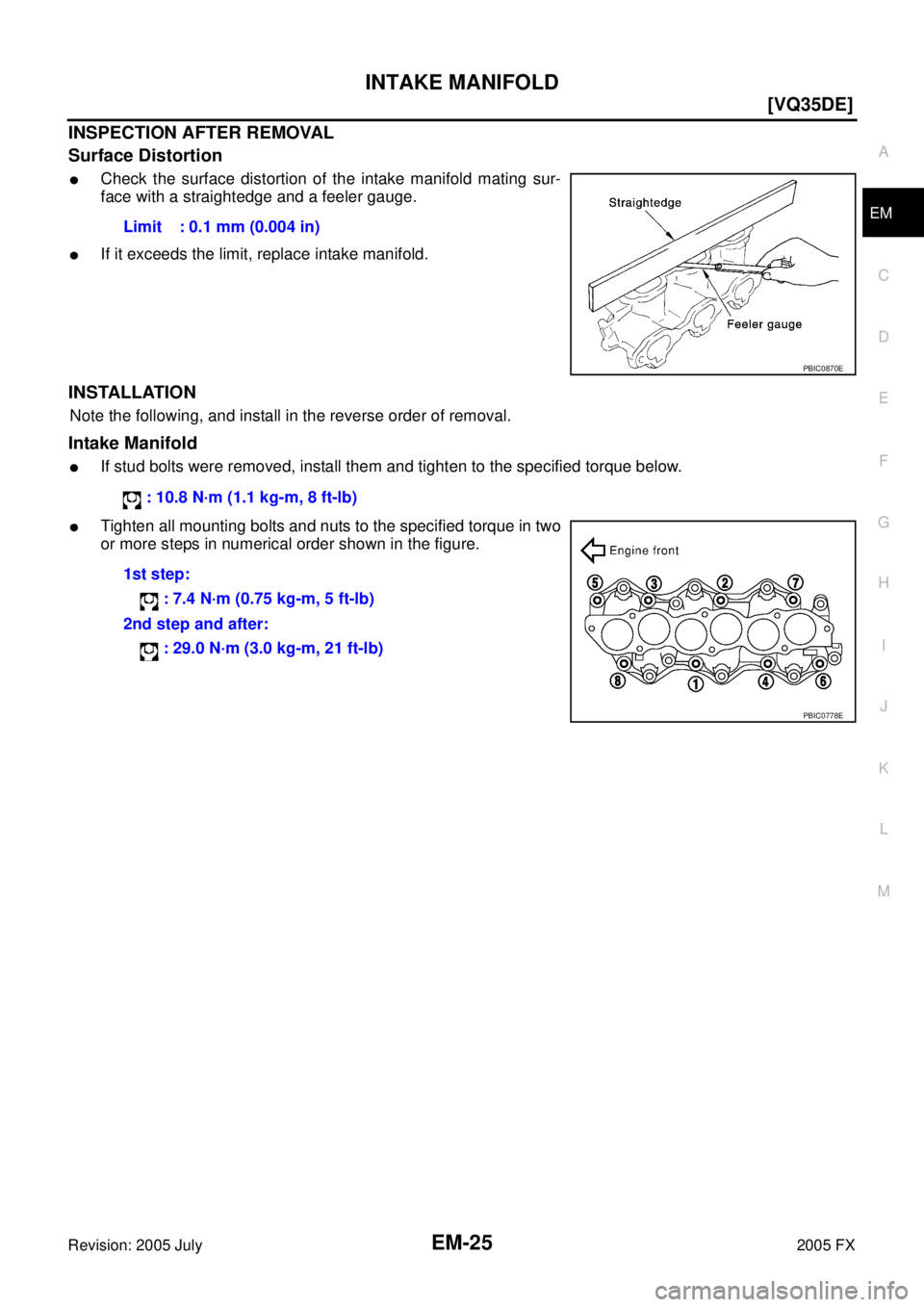
INSPECTION AFTER REMOVAL
Surface Distortion
�Check the surface distortion of the intake manifold mating sur-
face with a straightedge and a feeler gauge.
�If it exceeds the limit, replace intake manifold.
INSTALLATION
Note the following, and install in the reverse order of removal.
Intake Manifold
�If stud bolts were removed, install them and tighten to the specified torque below.
�Tighten all mounting bolts and nuts to the specified torque in two
or more steps in numerical order shown in the figure. Limit : 0.1 mm (0.004 in)
PBIC0870E
: 10.8 N·m (1.1 kg-m, 8 ft-lb)
1st step: : 7.4 N·m (0.75 kg-m, 5 ft-lb)
2nd step and after: : 29.0 N·m (3.0 kg-m, 21 ft-lb)
PBIC0778E
Page 2863 of 4731
![INFINITI FX35 2005 Service Manual EM-28
[VQ35DE]
EXHAUST MANIFOLD AND THREE WAY CATALYST
Revision: 2005 July 2005 FX
INSPECTION AFTER REMOVAL
Surface Distortion
�Check the surface distortion of the exhaust manifold mating sur-
face](/manual-img/42/57020/w960_57020-2862.png "INFINITI FX35 2005 Service Manual EM-28
[VQ35DE]
EXHAUST MANIFOLD AND THREE WAY CATALYST
Revision: 2005 July 2005 FX
INSPECTION AFTER REMOVAL
Surface Distortion
�Check the surface distortion of the exhaust manifold mating sur-
face")
EM-28
[VQ35DE]
EXHAUST MANIFOLD AND THREE WAY CATALYST
Revision: 2005 July 2005 FX
INSPECTION AFTER REMOVAL
Surface Distortion
�Check the surface distortion of the exhaust manifold mating sur-
face with a straightedge and a feeler gauge.
�If it exceeds the limit, replace exhaust manifold.
INSTALLATION
Note the following, and install in the reverse order of removal.
Exhaust Manifold Gasket
�Install in direction shown below. (Follow same procedure for
both banks.)
�Locate thick side of port connecting part on right side from tech-
nician’s view.
�Locate round press in thick side of port connecting part above
center level line of port.
Exhaust Manifold
�If stud bolts were removed, install them and tighten to the specified torque below.
�Install exhaust manifold and tighten mounting bolts in numerical
order as shown in the figure.
NOTE:
Tighten nuts No. 1 and 2 in two steps. The numerical order No. 7
and 8 shows second step. Limit : 0.3 mm (0.012 in)
PBIC1096E
KBIA1051E
: 14.7 N·m (1.5 kg-m, 11 ft-lb)
PBIC2042E
Page 2864 of 4731
EXHAUST MANIFOLD AND THREE WAY CATALYST EM-29
[VQ35DE]
C
D E
F
G H
I
J
K L
M A
EM
Revision: 2005 July 2005 FX
Air Fuel Ratio Sensor and Heated Oxygen Sensor
CAUTION:
�Before installing a new air fuel ratio sensor and new heated oxygen sensor, clean exhaust system
threads using heated oxygen sensor thread cleaner tool (Commercial Service Tool: J-43897-18 or
J-43897-12) and apply anti-seize lubricant.
�Do not over torque air fuel ratio sensor and heated oxygen sensor. Doing so may cause damage to
air fuel ratio sensor and heated oxygen sensor, resulting in the “MIL” coming on.
Page 2896 of 4731
![INFINITI FX35 2005 Service Manual FRONT TIMING CHAIN CASE EM-61
[VQ35DE]
C
D E
F
G H
I
J
K L
M A
EM
Revision: 2005 July 2005 FX
ii. Since front timing chain case is offset for difference of bolt holes,
tighten bolts temp](/manual-img/42/57020/w960_57020-2895.png "INFINITI FX35 2005 Service Manual FRONT TIMING CHAIN CASE EM-61
[VQ35DE]
C
D E
F
G H
I
J
K L
M A
EM
Revision: 2005 July 2005 FX
ii. Since front timing chain case is offset for difference of bolt holes,
tighten bolts temp")
FRONT TIMING CHAIN CASE EM-61
[VQ35DE]
C
D E
F
G H
I
J
K L
M A
EM
Revision: 2005 July 2005 FX
ii. Since front timing chain case is offset for difference of bolt holes,
tighten bolts temporarily with holding front timing chain case
from front and top as shown in the figure.
For bolt length and positions, refer to the step e.
iii. Same as the step ii, insert dowel pin with holding front timing chain case from front and top completely.
e. Tighten mounting bolts to the specified torque in numerical order as shown in the figure.
�There are two type of mounting bolts. Refer to the following
for locating bolts.
f. After all bolts tightened, retighten them to the specified torque in numerical order as shown in the figure.
6. Install two mounting bolts in front of oil pan (upper) in numerical order as shown in figure.
7. Install oil pan (lower). Refer to EM-30, "
OIL PAN AND OIL STRAINER" .
8. Install intake valve timing control covers as follows:
a. Install new seal rings in shaft grooves.
b. Apply a continuous bead of liquid gasket with the tube presser [SST: WS39930000 ( — )] to intake valve timing control cov-
ers as shown in the figure.
Use Genuine RTV Silicone Sealant or equivalent. Refer to
GI-48, "
RECOMMENDED CHEMICAL PRODUCTS AND
SEALANTS" .
PBIC1115E
M8 bolts : 1, 2
: 28.4 N·m (2.9 kg-m, 21 ft-lb)
M6 bolts : Except the above
: 12.7 N·m (1.3 kg-m, 9 ft-lb)
: 17.2 N·m (1.8 kg-m, 13 ft-lb)
KBIA1303E
PBIC1116E
SBIA0492E
Page 2910 of 4731
![INFINITI FX35 2005 Service Manual TIMING CHAIN EM-75
[VQ35DE]
C
D E
F
G H
I
J
K L
M A
EM
Revision: 2005 July 2005 FX
e. Tighten mounting bolts in numerical order as shown in the fig-
ure.
�There are two type mounting bol](/manual-img/42/57020/w960_57020-2909.png "INFINITI FX35 2005 Service Manual TIMING CHAIN EM-75
[VQ35DE]
C
D E
F
G H
I
J
K L
M A
EM
Revision: 2005 July 2005 FX
e. Tighten mounting bolts in numerical order as shown in the fig-
ure.
�There are two type mounting bol")
TIMING CHAIN EM-75
[VQ35DE]
C
D E
F
G H
I
J
K L
M A
EM
Revision: 2005 July 2005 FX
e. Tighten mounting bolts in numerical order as shown in the fig-
ure.
�There are two type mounting bolts. Refer to the following for
locating bolts.
f. After all bolts are tightened, retighten them to the specified torque in numerical order shown in the figure.
�If liquid gasket protrudes, wipe it off immediately.
g. After installing rear timing chain case, check the surface height difference between the following parts on the oil pan (upper)
mounting surface.
�If not within the standard, repeat the installation procedure.
3. Install water pump with new O-rings. Refer to CO-22, "
WATER PUMP" .
4. Make sure that dowel pin hole, dowel pin and crankshaft key are located as shown in the figure. (No. 1 cylinder at compression
TDC)
NOTE:
Though camshaft does not stop at the position as shown in the
figure, for the placement of cam nose, it is generally accepted
camshaft is placed for the same direction of the figure.
CAUTION:
Hole on small dia. side must be used for intake side dowel pin hole. Do not misidentify (ignore big
dia. side).
5. Install timing chains (secondary) and camshaft sprockets as follows: CAUTION:
Mating marks between timing chain and sprockets slip easily. Confirm all mating mark positions
repeatedly during the installation process. Bolt length: Bolt position
20 mm (0.79 in) : 1, 2, 3, 6, 7, 8, 9, 10
16 mm (0.63 in) : Except the above
: 12.7 N·m (1.3 kg-m, 9 ft-lb)
Standard Rear timing chain case to cylinder block: –0.24 to 0.14 mm (–0.009 to 0.006 in)
SEM735G
SEM943G
Camshaft dowel pin hole (intake side): At cylinder head upper face side in each bank.
Camshaft dowel pin (exhaust side) : At cylinder head upper face side in each bank.
Crankshaft key : At cylinder head side of right bank.
KBIA1073E