Page 1201 of 4731
![INFINITI FX35 2005 Service Manual BRC-60
[VDC/TCS/ABS]
ACTUATOR AND ELECTRIC UNIT (ASSEMBLY)
Revision: 2005 July 2005 FX
ACTUATOR AND ELECTRIC UNIT (ASSEMBLY)PFP:47660
Removal and InstallationAFS001Z5
REMOVAL
1. Disconnect ABS actuato](/manual-img/42/57020/w960_57020-1200.png "INFINITI FX35 2005 Service Manual BRC-60
[VDC/TCS/ABS]
ACTUATOR AND ELECTRIC UNIT (ASSEMBLY)
Revision: 2005 July 2005 FX
ACTUATOR AND ELECTRIC UNIT (ASSEMBLY)PFP:47660
Removal and InstallationAFS001Z5
REMOVAL
1. Disconnect ABS actuato")
BRC-60
[VDC/TCS/ABS]
ACTUATOR AND ELECTRIC UNIT (ASSEMBLY)
Revision: 2005 July 2005 FX
ACTUATOR AND ELECTRIC UNIT (ASSEMBLY)PFP:47660
Removal and InstallationAFS001Z5
REMOVAL
1. Disconnect ABS actuator and electric unit (control unit) connector.
2. Loosen brake tube flare nuts, then remove brake tubes from ABS actuator and electric unit (control unit).
3. Remove LH side fender protector. Refer to EI-24, "
FENDER PROTECTOR" .
4. Remove ABS actuator and electric unit (control unit) mounting nuts.
5. Remove ABS actuator and electric unit (control unit) from vehicle.
CAUTION:
Be careful of the following when removing ABS actuator and electric unit (control unit).
�If the part number on the part number label (pasted on actuator upper surface) is the same, ABS
actuator and electric unit (control unit) can not be used on another vehicle.
If it is used on another vehicle, ABS warning lamp, SLIP indicator lamp and VDC OFF indicator
lamp may turn ON or VDC/TCS/ABS may not operate normally.
When replacing ABS actuator and electric unit (control unit), must use new service parts.
�Before servicing, disconnect battery cables.
�To remove brake tube, use a flare nut torque wrench to prevent flare nuts and brake tube from
being damaged. To install, use a flare nut torque wrench (commercial service tool) and tighten to
the specified torque.
�Do not apply excessive impact to actuator, such as dropping it.
�Do not remove and install ABS actuator and electric unit (control unit) by holding harness.
INSTALLATION
Note the following, and install in the reverse order of removal.
CAUTION:
Be careful of the following when installing ABS actuator and electric unit (control unit).
�Tighten the mounting bolts and nuts to the specified torque.
�After the work, bleed air from brake piping. Refer to BR-10, "Bleeding Brake System" .
PFIA0601E
Page 1419 of 4731
EC-26
[VQ35DE]
PRECAUTIONS
Revision: 2005 July 2005 FX
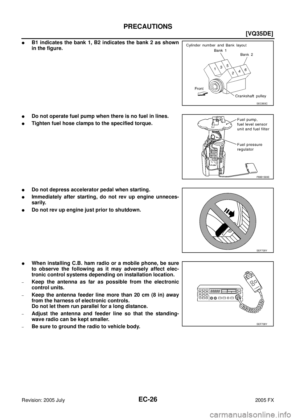
�B1 indicates the bank 1, B2 indicates the bank 2 as shown
in the figure.
�Do not operate fuel pump when there is no fuel in lines.
�Tighten fuel hose clamps to the specified torque.
�Do not depress accelerator pedal when starting.
�Immediately after starting, do not rev up engine unneces-
sarily.
�Do not rev up engine just prior to shutdown.
�When installing C.B. ham radio or a mobile phone, be sure
to observe the following as it may adversely affect elec-
tronic control systems depending on installation location.
–Keep the antenna as far as possible from the electronic
control units.
–Keep the antenna feeder line more than 20 cm (8 in) away
from the harness of electronic controls.
Do not let them run parallel for a long distance.
–Adjust the antenna and feeder line so that the standing-
wave radio can be kept smaller.
–Be sure to ground the radio to vehicle body.
SEC893C
PBIB1569E
SEF709Y
SEF708Y
Page 1567 of 4731
![INFINITI FX35 2005 Service Manual EC-174
[VQ35DE]
DTC P0011, P0021 IVT CONTROL
Revision: 2005 July 2005 FX
DTC P0011, P0021 IVT CONTROLPFP:23796
DescriptionABS006LE
SYSTEM DESCRIPTION
*: This signal is sent to the ECM through CAN comm](/manual-img/42/57020/w960_57020-1566.png "INFINITI FX35 2005 Service Manual EC-174
[VQ35DE]
DTC P0011, P0021 IVT CONTROL
Revision: 2005 July 2005 FX
DTC P0011, P0021 IVT CONTROLPFP:23796
DescriptionABS006LE
SYSTEM DESCRIPTION
*: This signal is sent to the ECM through CAN comm")
EC-174
[VQ35DE]
DTC P0011, P0021 IVT CONTROL
Revision: 2005 July 2005 FX
DTC P0011, P0021 IVT CONTROLPFP:23796
DescriptionABS006LE
SYSTEM DESCRIPTION
*: This signal is sent to the ECM through CAN communication line
This mechanism hydraulically controls cam phases continuously with the fixed operating angle of the intake
valve.
The ECM receives signals such as crankshaft position, camshaft position, engine speed, and engine coolant
temperature. Then, the ECM sends ON/OFF pulse duty signals to the intake valve timing control solenoid
valve depending on driving status. This makes it possible to control the shut/open timing of the intake valve to
increase engine torque in low/mid speed range and output in high-speed range.
CONSULT-II Reference Value in Data Monitor ModeABS006LF
Specification data are reference values.
Sensor Input signal to ECM ECM function Actuator
Crankshaft position sensor (POS) Engine speed and piston position
Intake valve
timing control Intake valve timing control
solenoid valve
Camshaft position sensor (PHASE)
Engine coolant temperature sensor Engine coolant temperature
Wheel sensor* Vehicle speed
PBIB1102E
MONITOR ITEM CONDITION SPECIFICATION
INT/V TIM (B1)
INT/V TIM (B2)
�Engine: After warming up
�Selector lever: P or N
�Air conditioner switch: OFF
�No-load Idle
−5° - 5 °CA
When revving engine up to 2,000 rpm
quickly Approx. 0
° - 30 °CA
INT/V SOL (B1)
INT/V SOL (B2)
�Engine: After warming up
�Selector lever: P or N
�Air conditioner switch: OFF
�No-load Idle 0% - 2%
When revving engine up to 2,000 rpm
quickly Approx. 0% - 50%
Page 1904 of 4731
![INFINITI FX35 2005 Service Manual DTC P1273, P1283 A/F SENSOR 1 EC-511
[VQ35DE]
C
D E
F
G H
I
J
K L
M A
EC
Revision: 2005 July 2005 FX
Specification data are reference values and are measured between each terminal and gro](/manual-img/42/57020/w960_57020-1903.png "INFINITI FX35 2005 Service Manual DTC P1273, P1283 A/F SENSOR 1 EC-511
[VQ35DE]
C
D E
F
G H
I
J
K L
M A
EC
Revision: 2005 July 2005 FX
Specification data are reference values and are measured between each terminal and gro")
DTC P1273, P1283 A/F SENSOR 1 EC-511
[VQ35DE]
C
D E
F
G H
I
J
K L
M A
EC
Revision: 2005 July 2005 FX
Specification data are reference values and are measured between each terminal and ground.
CAUTION:
Do not use ECM ground terminals when measuring input/output voltage. Doing so may result in dam-
age to the ECM's transistor. Use a ground other than ECM terminals, such as the ground.
Diagnostic ProcedureABS00AAC
1. CHECK GROUND CONNECTIONS
1. Turn ignition switch OFF.
2. Loosen and retighten ground three screws on the body. Refer to EC-170, "
Ground Inspection" .
OK or NG
OK >> GO TO 2.
NG >> Repair or replace ground connections.
2. RETIGHTEN AIR FUEL RATIO (A/F) SENSOR 1
Loosen and retighten the air fuel ratio (A/F) sensor 1.
>> GO TO 3.
TERMI- NAL NO. WIRE
COLOR ITEM CONDITION DATA (DC Voltage)
57 G A/F sensor 1 (Bank 2) [Engine is running]
�Warm-up condition
�Idle speed Approximately 2.6V
58 Y Approximately 2.3V
76 P Approximately 3.1V
77 BR Approximately 2.3V
PBIB2625E
Tightening torque: 40 - 60 N-m (4.1 - 6.1 kg-m, 30 - 44 ft-lb)
PBIB2200E
Page 1914 of 4731
![INFINITI FX35 2005 Service Manual DTC P1274, P1284 A/F SENSOR 1 EC-521
[VQ35DE]
C
D E
F
G H
I
J
K L
M A
EC
Revision: 2005 July 2005 FX
Specification data are reference values and are measured between each terminal and gro](/manual-img/42/57020/w960_57020-1913.png "INFINITI FX35 2005 Service Manual DTC P1274, P1284 A/F SENSOR 1 EC-521
[VQ35DE]
C
D E
F
G H
I
J
K L
M A
EC
Revision: 2005 July 2005 FX
Specification data are reference values and are measured between each terminal and gro")
DTC P1274, P1284 A/F SENSOR 1 EC-521
[VQ35DE]
C
D E
F
G H
I
J
K L
M A
EC
Revision: 2005 July 2005 FX
Specification data are reference values and are measured between each terminal and ground.
CAUTION:
Do not use ECM ground terminals when measuring input/output voltage. Doing so may result in dam-
age to the ECM's transistor. Use a ground other than ECM terminals, such as the ground.
Diagnostic ProcedureABS00AAJ
1. CHECK GROUND CONNECTIONS
1. Turn ignition switch OFF.
2. Loosen and retighten ground three screws on the body. Refer to EC-170, "
Ground Inspection" .
OK or NG
OK >> GO TO 2.
NG >> Repair or replace ground connections.
2. RETIGHTEN AIR FUEL RATIO (A/F) SENSOR 1
Loosen and retighten the air fuel ratio (A/F) sensor 1.
>> GO TO 3.
TERMI- NAL NO. WIRE
COLOR ITEM CONDITION DATA (DC Voltage)
57 G A/F sensor 1 (Bank 2) [Engine is running]
�Warm-up condition
�Idle speed Approximately 2.6V
58 Y Approximately 2.3V
76 P Approximately 3.1V
77 BR Approximately 2.3V
PBIB2625E
Tightening torque: 40 - 60 N-m (4.1 - 6.1 kg-m, 30 - 44 ft-lb)
PBIB2200E
Page 1935 of 4731
![INFINITI FX35 2005 Service Manual EC-542
[VQ35DE]
DTC P1278, P1288 A/F SENSOR 1
Revision: 2005 July 2005 FX
Specification data are reference values and are measured between each terminal and ground.
CAUTION:
Do not use ECM ground te](/manual-img/42/57020/w960_57020-1934.png "INFINITI FX35 2005 Service Manual EC-542
[VQ35DE]
DTC P1278, P1288 A/F SENSOR 1
Revision: 2005 July 2005 FX
Specification data are reference values and are measured between each terminal and ground.
CAUTION:
Do not use ECM ground te")
EC-542
[VQ35DE]
DTC P1278, P1288 A/F SENSOR 1
Revision: 2005 July 2005 FX
Specification data are reference values and are measured between each terminal and ground.
CAUTION:
Do not use ECM ground terminals when measuring input/output voltage. Doing so may result in dam-
age to the ECM's transistor. Use a ground other than ECM terminals, such as the ground.
Diagnostic ProcedureABS00AAY
1. CHECK GROUND CONNECTIONS
1. Turn ignition switch OFF.
2. Loosen and retighten ground three screws on the body. Refer to EC-170, "
Ground Inspection" .
OK or NG
OK >> GO TO 2.
NG >> Repair or replace ground connections.
2. RETIGHTEN AIR FUEL RATIO (A/F) SENSOR 1
Loosen and retighten the air fuel ratio (A/F) sensor 1.
>> GO TO 3.
TER-
MINAL NO. WIRE
COLOR ITEM CONDITION DATA (DC Voltage)
57 G A/F sensor 1 (Bank 2) [Engine is running]
�Warm-up condition
�Idle speed Approximately 2.6V
58 Y Approximately 2.3V
76 P Approximately 3.1V
77 BR Approximately 2.3V
PBIB2625E
Tightening torque: 40 - 60 N-m (4.1 - 6.1 kg-m, 30 - 44 ft-lb)
PBIB2200E
Page 1947 of 4731
![INFINITI FX35 2005 Service Manual EC-554
[VQ35DE]
DTC P1279, P1289 A/F SENSOR 1
Revision: 2005 July 2005 FX
Specification data are reference values and are measured between each terminal and ground.
CAUTION:
Do not use ECM ground te](/manual-img/42/57020/w960_57020-1946.png "INFINITI FX35 2005 Service Manual EC-554
[VQ35DE]
DTC P1279, P1289 A/F SENSOR 1
Revision: 2005 July 2005 FX
Specification data are reference values and are measured between each terminal and ground.
CAUTION:
Do not use ECM ground te")
EC-554
[VQ35DE]
DTC P1279, P1289 A/F SENSOR 1
Revision: 2005 July 2005 FX
Specification data are reference values and are measured between each terminal and ground.
CAUTION:
Do not use ECM ground terminals when measuring input/output voltage. Doing so may result in dam-
age to the ECM's transistor. Use a ground other than ECM terminals, such as the ground.
Diagnostic ProcedureABS00AB5
1. CHECK GROUND CONNECTIONS
1. Turn ignition switch OFF.
2. Loosen and retighten ground three screws on the body. Refer to EC-170, "
Ground Inspection" .
OK or NG
OK >> GO TO 2.
NG >> Repair or replace ground connections.
2. RETIGHTEN AIR FUEL RATIO (A/F) SENSOR 1
Loosen and retighten the air fuel ratio (A/F) sensor 1.
>> GO TO 3.
TER-
MINAL NO. WIRE
COLOR ITEM CONDITION DATA (DC Voltage)
57 G A/F sensor 1 (Bank 2) [Engine is running]
�Warm-up condition
�Idle speed Approximately 2.6V
58 Y Approximately 2.3V
76 P Approximately 3.1V
77 BR Approximately 2.3V
PBIB2625E
Tightening torque: 40 - 60 N-m (4.1 - 6.1 kg-m, 30 - 44 ft-lb)
PBIB2200E
Page 2091 of 4731
![INFINITI FX35 2005 Service Manual EC-698
[VQ35DE]
SNOW MODE SWITCH
Revision: 2005 July 2005 FX
SNOW MODE SWITCHPFP:25310
DescriptionABS00A2B
NOTE:
If DTC U1000 or U1001 are displayed, first perform the trouble diagnosis for DTC U1000](/manual-img/42/57020/w960_57020-2090.png "INFINITI FX35 2005 Service Manual EC-698
[VQ35DE]
SNOW MODE SWITCH
Revision: 2005 July 2005 FX
SNOW MODE SWITCHPFP:25310
DescriptionABS00A2B
NOTE:
If DTC U1000 or U1001 are displayed, first perform the trouble diagnosis for DTC U1000")
EC-698
[VQ35DE]
SNOW MODE SWITCH
Revision: 2005 July 2005 FX
SNOW MODE SWITCHPFP:25310
DescriptionABS00A2B
NOTE:
If DTC U1000 or U1001 are displayed, first perform the trouble diagnosis for DTC U1000, U1001.
Refer to EC-171, "
DTC U1000, U1001 CAN COMMUNICATION LINE" .
The snow mode switch signal is sent to the “unified meter and A/C amp.” from the snow mode switch. The
“unified meter and A/C amp.” then sends the signal to the ECM by CAN communication line.
The snow mode is used for driving or starting the vehicle on snowy roads or slippery areas. If the snow mode
is activated, the vehicle speed will not be accelerated immediately than your original pedal in due to avoid the
vehicle slip. In other words, ECM controls the rapid engine torque change by controlling the electric throttle
control actuator operating speed.
CONSULT-II Reference Value in the Data Monitor ModeABS00A2C
MONITOR ITEM CONDITION SPECIFICATION
SNOW MODE SW
�Ignition switch: ON SNOW MODE SW: ON ON
SNOW MODE SW: OFF OFF