Page 3382 of 4731

REAR WINDOW DEFOGGER GW-105
C
D E
F
G H
J
K L
M A
B
GW
Revision: 2005 July 2005 FX
Driver Side Door Mirror Defogger Circuit CheckAIS004RE
1. CHECK POWER SUPPLY CIRCUIT
1. Turn ignition switch OFF.
2. Disconnect door mirror (driver side) connector.
3. Turn ignition switch ON.
4. Check voltage between door mirror (driver side) connector and ground.
OK or NG
OK >> GO TO 2.
NG >> Repair or replace harness.
2. CHECK GROUND CIRCUIT
1. Turn ignition switch OFF.
2. Check continuity between door mirror (driver side) connector D2 terminal 2 and ground.
OK or NG
OK >> GO TO 3.
NG >> Repair or replace harness.
3. CHECK DOOR MIRROR DEFOGGER
1. Connector door mirror connector.
2. Check continuity between each door mirror connector D2 (driver side) terminals 1 and 2.
OK or NG
OK >> Check condition of harness and connector.
NG >> Replace door mirror (driver side).
Connector Terminal (Wire color)
Condition Voltage (V)
(Approx.)
(+) (–)
D2 1 (L) Ground Rear window defogger
switch ON Battery voltage
Rear window defogger
switch OFF 0
PIIA6216E
2 (B) – Ground : Continuity should exist.
PIIA6214E
1 (L) – 2 (B) : Continuity should exist.
PIIA6215E
Page 3383 of 4731

GW-106
REAR WINDOW DEFOGGER
Revision: 2005 July 2005 FX
Passenger Side Door Mirror Defogger Circuit Check AIS004RF
1. CHECK POWER SUPPLY CIRCUIT
1. Turn ignition switch OFF.
2. Disconnect door mirror (passenger side) connector.
3. Turn ignition switch ON.
4. Check voltage between door mirror (passenger side) connector and ground.
OK or NG
OK >> GO TO 2.
NG >> Repair or replace harness.
2. CHECK GROUND CIRCUIT
1. Turn ignition switch OFF.
2. Check continuity between door mirror (passenger side) connec- tor D32 terminal 2 and ground.
OK or NG
OK >> GO TO 3.
NG >> Repair or replace harness.
3. CHECK DOOR MIRROR DEFOGGER
1. Connector door mirror connector.
2. Check continuity between each door mirror connector D32 (pas- senger side) terminals 1 and 2.
OK or NG
OK >> Check condition of harness and connector.
NG >> Replace door mirror (passenger side).
Rear Window Defogger Signal CheckAIS004RG
1. CHECK REAR WINDOW DEFOGGER SWITCH LAMP
A/C and AV switch self-diagnosis is performed. Refer to AV- 3 7 , "
A/C and AV Switch Self-Diagnosis Function"
Does rear window defogger switch light?
YES >> GO TO 2.
NO >> Replace A/C and AV switch.
Connector Terminal (Wire color)
Condition Voltage (V)
(Approx.)
(+) (–)
D32 1 (L) Ground Rear window defogger
switch ON Battery voltage
Rear window defogger
switch OFF 0
PIIA6216E
2 (B) – Ground : Continuity should exist.
PIIA6214E
1 (L) – 2 (B) : Continuity should exist.
PIIA6215E
Page 3424 of 4731
![INFINITI FX35 2005 Service Manual PRECAUTIONS LAN-5
[CAN]
C
D E
F
G H
I
J
L
M A
B
LAN
Revision: 2005 July 2005 FX
[CAN]PRECAUTIONSPFP:00001
Precautions for Supplemental Restraint System (SRS) “AIR BAG” and “SEAT
B](/manual-img/42/57020/w960_57020-3423.png "INFINITI FX35 2005 Service Manual PRECAUTIONS LAN-5
[CAN]
C
D E
F
G H
I
J
L
M A
B
LAN
Revision: 2005 July 2005 FX
[CAN]PRECAUTIONSPFP:00001
Precautions for Supplemental Restraint System (SRS) “AIR BAG” and “SEAT
B")
PRECAUTIONS LAN-5
[CAN]
C
D E
F
G H
I
J
L
M A
B
LAN
Revision: 2005 July 2005 FX
[CAN]PRECAUTIONSPFP:00001
Precautions for Supplemental Restraint System (SRS) “AIR BAG” and “SEAT
BELT PRE-TENSIONER”
AKS00FCW
The Supplemental Restraint System such as “AIR BAG” and “SEAT BELT PRE-TENSIONER”, used along
with a front seat belt, helps to reduce the risk or severity of injury to the driver and front passenger for certain
types of collision. This system includes seat belt switch inputs and dual stage front air bag modules. The SRS
system uses the seat belt switches to determine the front air bag deployment, and may only deploy one front
air bag, depending on the severity of a collision and whether the front occupants are belted or unbelted.
Information necessary to service the system safely is included in the SRS and SB section of this Service Man-
ual.
WARNING:
�To avoid rendering the SRS inoperative, which could increase the risk of personal injury or death
in the event of a collision which would result in air bag inflation, all maintenance must be per-
formed by an authorized NISSAN/INFINITI dealer.
�Improper maintenance, including incorrect removal and installation of the SRS, can lead to per-
sonal injury caused by unintentional activation of the system. For removal of Spiral Cable and Air
Bag Module, see the SRS section.
�Do not use electrical test equipment on any circuit related to the SRS unless instructed to in this
Service Manual. SRS wiring harnesses can be identified by yellow and/or orange harnesses or
harness connectors.
Precautions When Using CONSULT-IIAKS0058H
When connecting CONSULT-II to data link connector, connect them through CONSULT-II CONVERTER.
CAUTION:
If CONSULT-II is used with no connection of CONSULT-II CONVERTER, malfunctions might be
detected in self-diagnosis depending on control unit which carry out CAN communication.
CHECK POINTS FOR USING CONSULT-II
1. Has CONSULT-II been used without connecting CONSULT-II CONVERTER on this vehicle?
–If YES, GO TO 2.
–If NO, GO TO 5.
2. Is there any indication other than indications relating to CAN communication system in the self-diagnosis results?
–If YES, GO TO 3.
–If NO, GO TO 4.
3. Based on self-diagnosis results unrelated to CAN communication, carry out the inspection.
4. Malfunctions may be detected in self-diagnosis depending on control units carrying out CAN communica- tion. Therefore, erase the self-diagnosis results.
5. Diagnose CAN communication system. Refer to LAN-7, "
TROUBLE DIAGNOSES WORK FLOW" .
Precautions For Trouble DiagnosisAKS0058I
CAN SYSTEM
�Do not apply voltage of 7.0 V or higher to the measurement terminals.
�Use the tester with its open terminal voltage being 7.0 V or less.
�Be sure to turn ignition switch OFF and disconnect the battery cable from the negative terminal before
checking the circuit.
Page 3451 of 4731
![INFINITI FX35 2005 Service Manual LAN-32
[CAN]
CAN COMMUNICATION
Revision: 2005 July 2005 FX
Ignition switch signal T R R
P range signal T R R
Stop lamp switch signal R T
Fuel consumption monitor signal TR
RT
Turbine revolution s](/manual-img/42/57020/w960_57020-3450.png "INFINITI FX35 2005 Service Manual LAN-32
[CAN]
CAN COMMUNICATION
Revision: 2005 July 2005 FX
Ignition switch signal T R R
P range signal T R R
Stop lamp switch signal R T
Fuel consumption monitor signal TR
RT
Turbine revolution s")
LAN-32
[CAN]
CAN COMMUNICATION
Revision: 2005 July 2005 FX
Ignition switch signal T R R
P range signal T R R
Stop lamp switch signal R T
Fuel consumption monitor signal TR
RT
Turbine revolution signal R T
Output shaft revolution signal R T R
A/C switch signal R T
A/C compressor request signal T R
A/C compressor feedback signal T R
Blower fan motor switch signal R T
A/C switch/indicator signal TR
RT
Cooling fan speed request signal T R
Position light request signal R T R R
Low beam request signal T R
Low beam status signal R T
High beam request signal T R R
High beam status signal R T
Front fog light request signal T R
Day time running light request
signal TR
Turn LED burnout status signal R T
Vehicle speed signal RR T
RRRR T R
Sleep wake up signal T R R
Door switch signal R T R R R
Turn indicator signal T R R
Key fob ID signal T R
Key fob door unlock signal T R
Oil pressure switch signal RT
TR
Buzzer output signal T R
Fuel level sensor signal R T
Fuel level low warning signal R T
ASCD SET lamp signal T R
ASCD CRUISE lamp signal T R
Malfunction indicator lamp signal T R
ASCD operation signal T R
ASCD OD cancel request signal T R Signals ECM TCM
Dis-
play unit BCM Steer-
ing
angle
sensor LDW
cam-
era unit Unified
meter and
A/C
amp. ABS
actua-
tor and elec-
tric unit (con-trol
unit) Driver
seat
control unit IPDM
E/R
Page 3454 of 4731
![INFINITI FX35 2005 Service Manual CAN COMMUNICATION LAN-35
[CAN]
C
D E
F
G H
I
J
L
M A
B
LAN
Revision: 2005 July 2005 FX
Closed throttle position
signal TR R
Wide open throttle posi-
tion signal TR
Battery voltage](/manual-img/42/57020/w960_57020-3453.png "INFINITI FX35 2005 Service Manual CAN COMMUNICATION LAN-35
[CAN]
C
D E
F
G H
I
J
L
M A
B
LAN
Revision: 2005 July 2005 FX
Closed throttle position
signal TR R
Wide open throttle posi-
tion signal TR
Battery voltage")
CAN COMMUNICATION LAN-35
[CAN]
C
D E
F
G H
I
J
L
M A
B
LAN
Revision: 2005 July 2005 FX
Closed throttle position
signal TR R
Wide open throttle posi-
tion signal TR
Battery voltage signal T R
Key switch signal T R
Ignition switch signal T R R
P range signal T R R R
Stop lamp switch signal R T
ABS operation signal R T
TCS operation signal R T
VDC operation signal R T
Fuel consumption moni-
tor signal TR
RT
Turbine revolution signal R T R
Output shaft revolution
signal RT R R
A/C switch signal R T
A/C compressor request
signal T
R
A/C compressor feed-
back signal TR
Blower fan motor switch
signal RT
A/C switch/indicator sig-
nal TR
RT
Cooling fan speed
request signal T
R
Position light request sig-
nal TR R
Low beam request signal T R
Low beam status signal R T
High beam request sig-
nal TR R
High beam status signal R T
Front fog light request
signal TR
Day time running light
request signal TR
Turn LED burnout status
signal RT
Signals ECM TCM
Dis-
play
con-
trol
unit ICC
unit Intelli-
gent Key unit BCM Ste er-
ing
angle
sen- sor LDW
cam- era
unit Uni-
fied
meter and
A/C
amp. ICC
sen-
sor ABS
actu- ator and
elec- tric
unit
(con- trol
unit) Driver
seat
con-
trol
unit IPDM
E/R
Page 3457 of 4731
LAN-38
[CAN]
CAN COMMUNICATION
Revision: 2005 July 2005 FX
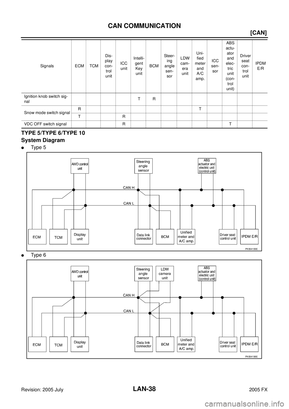
TYPE 5/TYPE 6/TYPE 10
System Diagram
�Ty p e 5
�Ty p e 6
Ignition knob switch sig-
nal TR
Snow mode switch signal RT
TR
VDC OFF switch signal R T Signals ECM TCM
Dis-
play
con-
trol
unit ICC
unit Intelli-
gent Key unit BCM St e e r-
ing
angle
sen- sor LDW
cam- era
unit Uni-
fied
meter and
A/C
amp. ICC
sen-
sor ABS
actu- ator and
elec- tric
unit
(con- trol
unit) Driver
seat
con-
trol
unit IPDM
E/R
PKIB4199E
PKIB4198E
Page 3458 of 4731
CAN COMMUNICATION LAN-39
[CAN]
C
D E
F
G H
I
J
L
M A
B
LAN
Revision: 2005 July 2005 FX
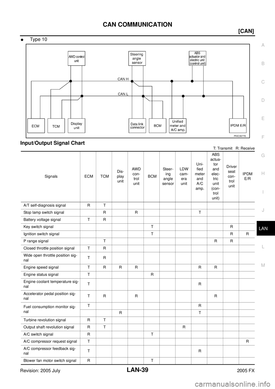
�Type 10
Input/Output Signal Chart
T: Transmit R: Receive
PKIC3677E
Signals ECM TCM Dis-
play unit AWD
con- trol
unit BCM Steer-
ing
angle
sensor LDW
cam- era
unit Uni-
fied
meter and
A/C
amp. ABS
actua- tor
and
elec- tric
unit
(con- trol
unit) Driver
seat
con- trol
unit IPDM
E/R
A/T self-diagnosis signal R T
Stop lamp switch signal R R T
Battery voltage signal T R
Key switch signal T R
Ignition switch signal T R R
P range signal T R R
Closed throttle position signal T R
Wide open throttle position sig-
nal TR
Engine speed signal T R R R R R
Engine status signal T R
Engine coolant temperature sig-
nal TR
Accelerator pedal position sig-
nal TR R R
Fuel consumption monitor sig-
nal TR
RT
Turbine revolution signal R T
Output shaft revolution signal R T R
A/C switch signal R T
A/C compressor request signal T R
A/C compressor feedback sig-
nal TR
Blower fan motor switch signal R T
Page 3462 of 4731
![INFINITI FX35 2005 Service Manual CAN COMMUNICATION LAN-43
[CAN]
C
D E
F
G H
I
J
L
M A
B
LAN
Revision: 2005 July 2005 FX
Battery voltage sig-
nal TR
Key switch signal T R
Ignition switch signal T R R
P range signal T](/manual-img/42/57020/w960_57020-3461.png "INFINITI FX35 2005 Service Manual CAN COMMUNICATION LAN-43
[CAN]
C
D E
F
G H
I
J
L
M A
B
LAN
Revision: 2005 July 2005 FX
Battery voltage sig-
nal TR
Key switch signal T R
Ignition switch signal T R R
P range signal T")
CAN COMMUNICATION LAN-43
[CAN]
C
D E
F
G H
I
J
L
M A
B
LAN
Revision: 2005 July 2005 FX
Battery voltage sig-
nal TR
Key switch signal T R
Ignition switch signal T R R
P range signal T R R R
Closed throttle posi-
tion signal TR R
Wide open throttle
position signal TR
Engine speed signal T R R R R R R
Engine status signal T R
Engine coolant tem-
perature signal TR
Accelerator pedal
position signal TR R R R
Fuel consumption
monitor signal TR
RT
Turbine revolution
signal RT R
Output shaft revolu-
tion signal RT R R
A/C switch signal R T
A/C compressor
request signal T
R
A/C compressor
feedback signal TR
Blower fan motor
switch signal RT
A/C switch/indicator
signal TR
RT
Cooling fan speed
request signal T
R
Position light request
signal RTR R
Low beam request
signal TR
Low beam status sig-
nal R
T
High beam request
signal TR R
High beam status
signal R
T
Front fog light
request signal TR
Signals ECM TCM
Dis-
play
con-
trol
unit AWD
con- trol
unit ICC
unit Intel-
ligent Key unit BCM Steer-
ing
angle
sen- sor LDW
cam- era
unit Uni-
fied
meter and
A/C
amp. ICC
sen-
sor ABS
actu- ator and
elec- tric
unit
(con- trol
unit) Driver
seat
con-
trol
unit IPDM
E/R