Page 494 of 4731
TROUBLE DIAGNOSIS ATC-57
C
D E
F
G H
I
K L
M A
B
AT C
Revision: 2005 July 2005 FX
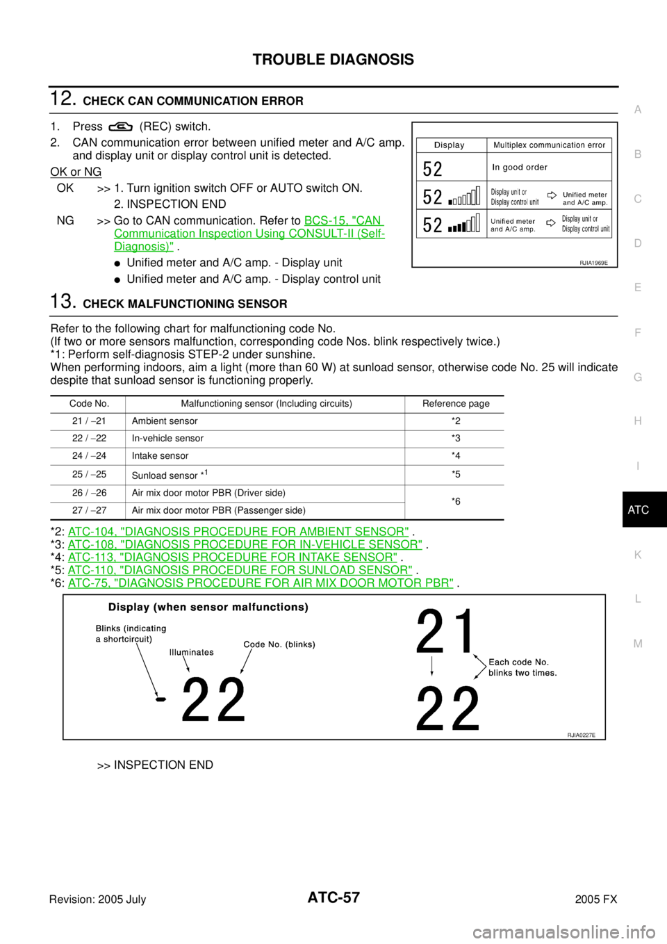
12. CHECK CAN COMMUNICATION ERROR
1. Press (REC) switch.
2. CAN communication error between unified meter and A/C amp. and display unit or display control unit is detected.
OK or NG
OK >> 1. Turn ignition switch OFF or AUTO switch ON. 2. INSPECTION END
NG >> Go to CAN communication. Refer to BCS-15, "
CAN
Communication Inspection Using CONSULT-II (Self-
Diagnosis)" .
�Unified meter and A/C amp. - Display unit
�Unified meter and A/C amp. - Display control unit
13. CHECK MALFUNCTIONING SENSOR
Refer to the following chart for malfunctioning code No.
(If two or more sensors malfunction, corresponding code Nos. blink respectively twice.)
*1: Perform self-diagnosis STEP-2 under sunshine.
When performing indoors, aim a light (more than 60 W) at sunload sensor, otherwise code No. 25 will indicate
despite that sunload sensor is functioning properly.
*2: ATC-104, "
DIAGNOSIS PROCEDURE FOR AMBIENT SENSOR" .
*3: ATC-108, "
DIAGNOSIS PROCEDURE FOR IN-VEHICLE SENSOR" .
*4: AT C - 11 3 , "
DIAGNOSIS PROCEDURE FOR INTAKE SENSOR" .
*5: AT C - 11 0 , "
DIAGNOSIS PROCEDURE FOR SUNLOAD SENSOR" .
*6: AT C - 7 5 , "
DIAGNOSIS PROCEDURE FOR AIR MIX DOOR MOTOR PBR" .
>> INSPECTION END
RJIA1969E
Code No. Malfunctioning sensor (Including circuits) Reference page 21 / −21 Ambient sensor *2
22 / −22 In-vehicle sensor *3
24 / −24 Intake sensor *4
25 / −25
Sunload sensor *
1*5
26 / −26 Air mix door motor PBR (Driver side)
*6
27 / −27 Air mix door motor PBR (Passenger side)
RJIA0227E
Page 497 of 4731
ATC-60
TROUBLE DIAGNOSIS
Revision: 2005 July 2005 FX
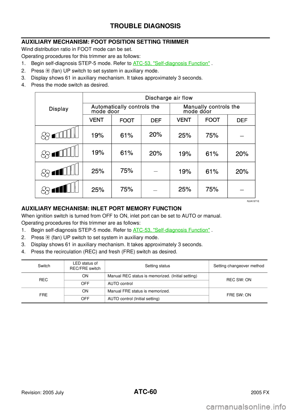
AUXILIARY MECHANISM: FOOT POSITION SETTING TRIMMER
Wind distribution ratio in FOOT mode can be set.
Operating procedures for this trimmer are as follows:
1. Begin self-diagnosis STEP-5 mode. Refer to AT C - 5 3 , "
Self-diagnosis Function" .
2. Press (fan) UP switch to set system in auxiliary mode.
3. Display shows 61 in auxiliary mechanism. It takes approximately 3 seconds.
4. Press the mode switch as desired.
AUXILIARY MECHANISM: INLET PORT MEMORY FUNCTION
When ignition switch is turned from OFF to ON, inlet port can be set to AUTO or manual.
Operating procedures for this trimmer are as follows:
1. Begin self-diagnosis STEP-5 mode. Refer to AT C - 5 3 , "
Self-diagnosis Function" .
2. Press (fan) UP switch to set system in auxiliary mode.
3. Display shows 61 in auxiliary mechanism. It takes approximately 3 seconds.
4. Press the recirculation (REC) and fresh (FRE) switch as desired.
RJIA1971E
Switch LED status of
REC/FRE switch Setting status Setting changeover method
REC ON Manual REC status is memorized. (Initial setting)
REC SW: ON
OFF AUTO control
FRE ON Manual FRE status is memorized.
FRE SW: ON
OFF AUTO control (Initial setting)
Page 498 of 4731
TROUBLE DIAGNOSIS ATC-61
C
D E
F
G H
I
K L
M A
B
AT C
Revision: 2005 July 2005 FX
Operational CheckAJS0014Q
The purpose of the operational check is to check if the individual system operates properly.
CHECKING MEMORY FUNCTION
1. Set the temperature to 32°C (90 °F).
2. Press OFF switch.
3. Turn ignition switch OFF.
4. Turn ignition switch ON.
5. Press the AUTO switch.
6. Confirm that the set temperature remains at previous tempera- ture.
7. Press OFF switch.
If NG, go to trouble diagnosis procedure for ATC-103, "
Memory
Function" .
If OK, continue the check.
CHECKING BLOWER
1. Press fan (UP) switch. Blower should operate on low speed. The
fan symbol should have one blade lit.
2. Press fan (UP) switch again, and continue checking blower speed and fan symbol until all speeds are checked.
3. Leave blower on max. speed.
If NG, go to trouble diagnosis procedure for AT C - 7 9 , "
Blower Motor
Circuit" .
If OK, continue the check.
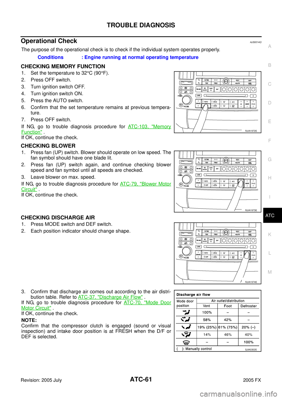
CHECKING DISCHARGE AIR
1. Press MODE switch and DEF switch.
2. Each position indicator should change shape.
3. Confirm that discharge air comes out according to the air distri- bution table. Refer to AT C - 3 7 , "
Discharge Air Flow" .
If NG, go to trouble diagnosis procedure for AT C - 7 0 , "
Mode Door
Motor Circuit" .
If OK, continue the check.
NOTE:
Confirm that the compressor clutch is engaged (sound or visual
inspection) and intake door position is at FRESH when the D/F or
DEF is selected. Conditions : Engine running at normal operating temperature
RJIA1972E
RJIA1973E
RJIA1974E
SJIA0302E
Page 502 of 4731
TROUBLE DIAGNOSIS ATC-65
C
D E
F
G H
I
K L
M A
B
AT C
Revision: 2005 July 2005 FX
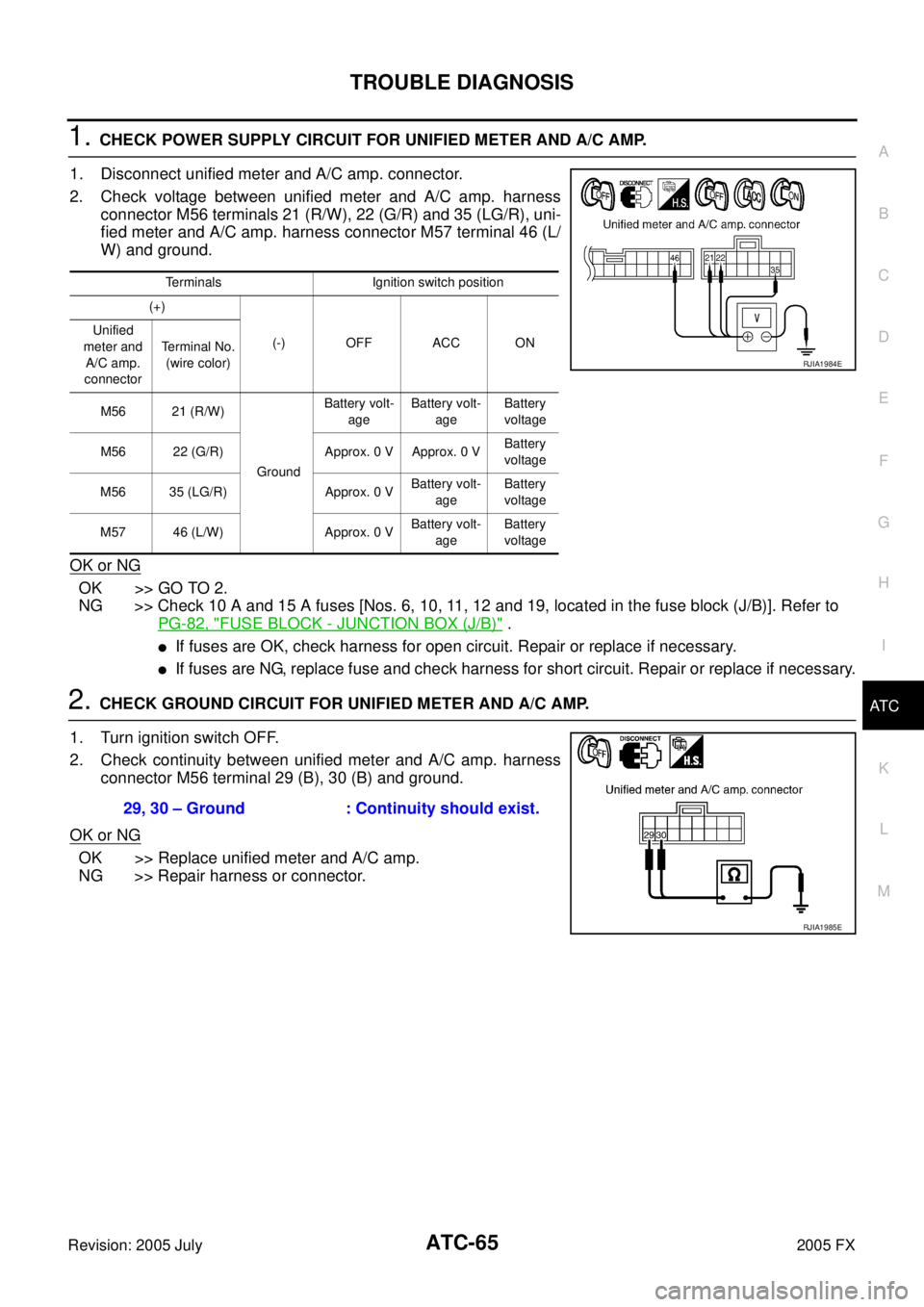
1. CHECK POWER SUPPLY CIRCUIT FOR UNIFIED METER AND A/C AMP.
1. Disconnect unified meter and A/C amp. connector.
2. Check voltage between unified meter and A/C amp. harness connector M56 terminals 21 (R/W), 22 (G/R) and 35 (LG/R), uni-
fied meter and A/C amp. harness connector M57 terminal 46 (L/
W) and ground.
OK or NG
OK >> GO TO 2.
NG >> Check 10 A and 15 A fuses [Nos. 6, 10, 11, 12 and 19, located in the fuse block (J/B)]. Refer to
PG-82, "
FUSE BLOCK - JUNCTION BOX (J/B)" .
�If fuses are OK, check harness for open circuit. Repair or replace if necessary.
�If fuses are NG, replace fuse and check harness for short circuit. Repair or replace if necessary.
2. CHECK GROUND CIRCUIT FOR UNIFIED METER AND A/C AMP.
1. Turn ignition switch OFF.
2. Check continuity between unified meter and A/C amp. harness connector M56 terminal 29 (B), 30 (B) and ground.
OK or NG
OK >> Replace unified meter and A/C amp.
NG >> Repair harness or connector.
Terminals Ignition switch position
(+)
(-) OFF ACC ON
Unified
meter and A/C amp.
connector Terminal No.
(wire color)
M56 21 (R/W)
Ground Battery volt-
age Battery volt-
age Battery
voltage
M56 22 (G/R) Approx. 0 V Approx. 0 V Battery
voltage
M56 35 (LG/R) Approx. 0 V Battery volt-
age Battery
voltage
M57 46 (L/W) Approx. 0 V Battery volt-
age Battery
voltage
RJIA1984E
29, 30 – Ground : Continuity should exist.
RJIA1985E
Page 503 of 4731
ATC-66
TROUBLE DIAGNOSIS
Revision: 2005 July 2005 FX
LAN System CircuitAJS0014S
SYMPTOM: Mode door motor, intake door motor and/or air mix door motor(s) does not operate normally.
DIAGNOSIS PROCEDURE FOR LAN CIRCUIT
1. CHECK POWER SUPPLY FOR UNIFIED METER AND A/C AMP.
1. Turn ignition switch ON.
2. Check voltage between unified meter and A/C amp. harness connector M57 terminal 54 (Y/R) and ground.
OK or NG
OK >> GO TO 2.
NG >> Replace unified meter and A/C amp.
2. CHECK SIGNAL FOR UNIFIED METER AND A/C AMP.
Confirm A/C LAN signal between unified meter and A/C amp. har-
ness connector M57 terminal 43 (G/B) and ground using an oscillo-
scope.
OK or NG
OK >> GO TO 3.
NG >> Replace unified meter and A/C amp.
RJIA1775E
54 – Ground : Battery voltage
RJIA1986E
Terminals
Voltage
(+)
( − )
Unified meter and A/
C amp. connector Terminal No.
(wire color)
M57 43 (G/B) Ground
RJIA1987E
HAK0652D
Page 504 of 4731
TROUBLE DIAGNOSIS ATC-67
C
D E
F
G H
I
K L
M A
B
AT C
Revision: 2005 July 2005 FX
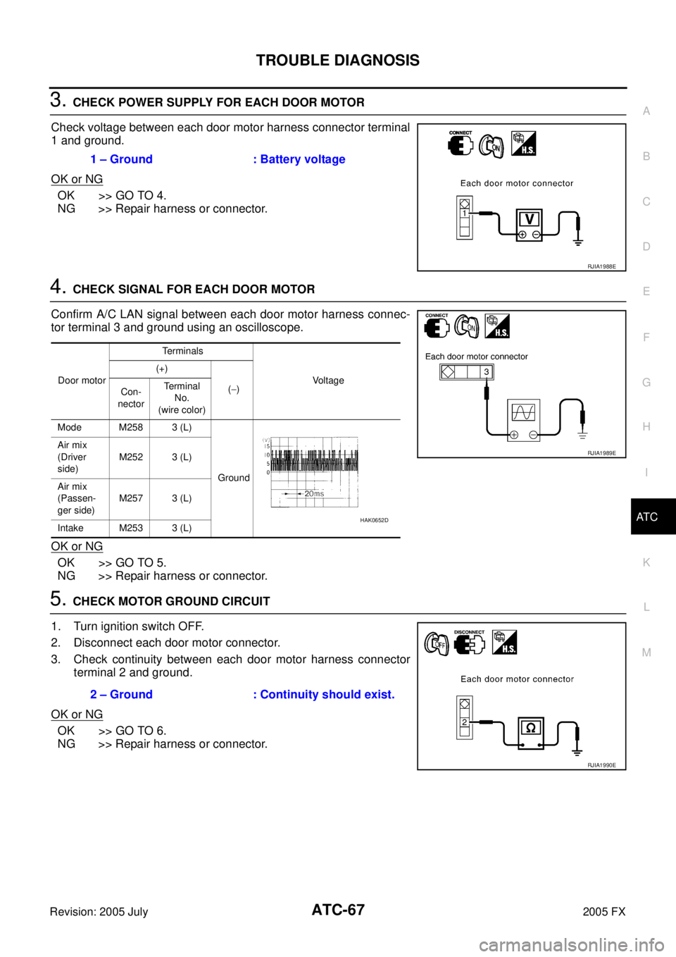
3. CHECK POWER SUPPLY FOR EACH DOOR MOTOR
Check voltage between each door motor harness connector terminal
1 and ground.
OK or NG
OK >> GO TO 4.
NG >> Repair harness or connector.
4. CHECK SIGNAL FOR EACH DOOR MOTOR
Confirm A/C LAN signal between each door motor harness connec-
tor terminal 3 and ground using an oscilloscope.
OK or NG
OK >> GO TO 5.
NG >> Repair harness or connector.
5. CHECK MOTOR GROUND CIRCUIT
1. Turn ignition switch OFF.
2. Disconnect each door motor connector.
3. Check continuity between each door motor harness connector terminal 2 and ground.
OK or NG
OK >> GO TO 6.
NG >> Repair harness or connector. 1 – Ground : Battery voltage
RJIA1988E
Door motor
Terminals
Voltage
(+)
( − )
Con-
nector Terminal
No.
(wire color)
Mode M258 3 (L)
Ground
Air mix
(Driver
side) M252 3 (L)
Air mix
(Passen-
ger side) M257 3 (L)
Intake M253 3 (L)
RJIA1989E
HAK0652D
2 – Ground : Continuity should exist.
RJIA1990E
Page 505 of 4731

ATC-68
TROUBLE DIAGNOSIS
Revision: 2005 July 2005 FX
6. CHECK MOTOR OPERATION
1. Turn ignition switch OFF.
2. Disconnect each door motor connector.
3. Reconnect each door motor connector.
4. Turn ignition switch ON.
5. Confirm operation of each door motor.
OK or NG
OK >> (Return to operate normally.)
�Poor contact in motor connector.
NG >> (Does not operate normally.)
�GO TO 7.
7. CHECK OPERATION OF AIR MIX DOOR MOTOR AND INTAKE DOOR MOTOR
1. Turn ignition switch OFF.
2. Disconnect mode, air mix (driver side, passenger side), and intake door motor connectors.
3. Reconnect air mix (driver side, passenger side) and intake door motor connectors.
4. Turn ignition switch ON.
5. Confirm operation of air mix door motor (driver side, passenger side) and intake door motor.
OK or NG
OK >> [Air mix (driver side, passenger side) and intake door motors operate normally.]
�Replace mode door motor.
NG >> [Air mix (driver side, passenger side) and intake door motors does not operate normally.]
�GO TO 8.
8. CHECK OPERATION OF MODE DOOR MOTOR AND INTAKE DOOR MOTOR
1. Turn ignition switch OFF.
2. Disconnect air mix door motor (driver side, passenger side) connectors.
3. Reconnect mode door motor connector.
4. Turn ignition switch ON.
5. Confirm operation of mode door motor and intake door motor.
OK or NG
OK >> (Mode and intake door motors operate normally.)
�GO TO 10.
NG >> (Mode and intake door motors does not operate normally.)
�GO TO 9.
9. CHECK OPERATION OF MODE DOOR MOTOR AND AIR MIX DOOR MOTOR
1. Turn ignition switch OFF.
2. Disconnect intake door motor connector.
3. Reconnect air mix door motor (driver side, passenger side) connectors.
4. Turn ignition switch ON.
5. Confirm operation of mode door motor and air mix door motor (driver side, passenger side).
OK or NG
OK >> [Mode and air mix door motor (driver side, passenger side) operate normally.]
�Replace intake door motor.
NG >> [Mode and air mix door motor (driver side, passenger side) does not operate normally.]
�Replace display and A/C auto amp.
Page 506 of 4731
TROUBLE DIAGNOSIS ATC-69
C
D E
F
G H
I
K L
M A
B
AT C
Revision: 2005 July 2005 FX
10. CHECK OPERATION OF AIR MIX DOOR MOTOR
1. Turn ignition switch OFF.
2. Disconnect air mix door motor (driver side) connector.
3. Turn ignition switch ON.
4. Confirm operation of air mix door motor (passenger side).
OK or NG
OK >> [Air mix door motor (passenger side) operates normally.]
�Replace air mix door motor (driver side).
NG >> [Air mix door motor (passenger side) does not operate normally.]
�Replace air mix door motor (passenger side).