Page 442 of 4731

PRECAUTIONS ATC-5
C
D E
F
G H
I
K L
M A
B
AT C
Revision: 2005 July 2005 FX
PRECAUTIONSPFP:00001
Precautions for Supplemental Restraint System (SRS) “AIR BAG” and “SEAT
BELT PRE-TENSIONER”
AJS001XF
The Supplemental Restraint System such as “AIR BAG” and “SEAT BELT PRE-TENSIONER”, used along
with a front seat belt, helps to reduce the risk or severity of injury to the driver and front passenger for certain
types of collision. This system includes seat belt switch inputs and dual stage front air bag modules. The SRS
system uses the seat belt switches to determine the front air bag deployment, and may only deploy one front
air bag, depending on the severity of a collision and whether the front occupants are belted or unbelted.
Information necessary to service the system safely is included in the SRS and SB section of this Service Man-
ual.
WARNING:
�To avoid rendering the SRS inoperative, which could increase the risk of personal injury or death
in the event of a collision which would result in air bag inflation, all maintenance must be per-
formed by an authorized NISSAN/INFINITI dealer.
�Improper maintenance, including incorrect removal and installation of the SRS, can lead to per-
sonal injury caused by unintentional activation of the system. For removal of Spiral Cable and Air
Bag Module, see the SRS section.
�Do not use electrical test equipment on any circuit related to the SRS unless instructed to in this
Service Manual. SRS wiring harnesses can be identified by yellow and/or orange harnesses or
harness connectors.
Precautions Necessary for Steering Wheel Rotation After Battery DisconnectAJS001XG
NOTE:
�This Procedure is applied only to models with Intelligent Key system and NVIS/IVIS (NISSAN/INFINITI
VEHICLE IMMOBILIZER SYSTEM - NATS).
�Remove and install all control units after disconnecting both battery cables with the ignition knob in the
″ LOCK ″ position.
�Always use CONSULT-II to perform self-diagnosis as a part of each function inspection after finishing
work. If DTC is detected, perform trouble diagnosis according to self-diagnostic results.
For models equipped with the Intelligent Key system and NVIS/IVIS, an electrically controlled steering lock
mechanism is adopted on the key cylinder.
For this reason, if the battery is disconnected or if the battery is discharged, the steering wheel will lock and
steering wheel rotation will become impossible.
If steering wheel rotation is required when battery power is interrupted, follow the procedure below before
starting the repair operation.
OPERATION PROCEDURE
1. Connect both battery cables.
NOTE:
Supply power using jumper cables if battery is discharged.
2. Use the Intelligent Key or mechanical key to turn the ignition switch to the ″ACC ″ position. At this time, the
steering lock will be released.
3. Disconnect both battery cables. The steering lock will remain released and the steering wheel can be rotated.
4. Perform the necessary repair operation.
5. When the repair work is completed, return the ignition switch to the ″LOCK ″ position before connecting
the battery cables. (At this time, the steering lock mechanism will engage.)
6. Perform a self-diagnosis check of all control units using CONSULT-II.
Page 459 of 4731

ATC-22
REFRIGERATION SYSTEM
Revision: 2005 July 2005 FX
V-6 Variable Displacement CompressorAJS001BE
GENERAL INFORMATION
1. The V-6 variable compressor differs from previous units. The vent temperatures of the V-6 variable com-
pressor do not drop too far below 5 °C (41 °F) when:
Evaporator intake air temperature is less than 20 °C (68 °F).
Engine is running at speeds less than 1,500 rpm.
This is because the V-6 compressor provides a means of “capacity” control.
2. The V-6 variable compressor provides refrigerant control under varying conditions. During cold winters, it may not produce high refrigerant pressure discharge (compared to previous units) when used with air
conditioning systems.
3. A “clanking” sound may occasionally be heard during refrigerant charge. The sound indicates that the tilt angle of the wobble (swash) plate has changed and is not a malfunction.
4. For air conditioning systems with the V-6 compressor, the clutch remains engaged unless: the system main switch, fan switch or ignition switch is turned OFF. When ambient (outside) temperatures are low or
when the amount of refrigerant is insufficient, the clutch is disengaged to protect the compressor.
Page 477 of 4731
ATC-40
TROUBLE DIAGNOSIS
Revision: 2005 July 2005 FX
TROUBLE DIAGNOSISPFP:00004
CONSULT-II Function (BCM)AJS0014J
CONSULT-II can display each diagnosis item using the diagnosis test modes shown following.
CONSULT-II BASIC OPERATION
CAUTION:
If CONSULT-II is used with no connection of CONSULT-II CONVERTER, malfunctions might be
detected in self-diagnosis depending on control unit which carry out CAN communication.
1. With the ignition switch OFF, connect CONSULT-II and “CON- SULT-II CONVERTER” to the data link connector, and then turn
the ignition switch ON.
2. Touch “START (NISSAN BASED VHCL)”.
3. Touch “BCM” on “SELECT SYSTEM” screen. If “BCM” is not indicated, refer to GI-39, "
CONSULT-II Data Link Connector
(DLC) Circuit" .
System part Check item, diagnosis mode Description
BCM Data monitor Displays BCM input data in real time.
PBIB1503E
BCIA0029E
BCIA0030E
Page 478 of 4731

TROUBLE DIAGNOSIS ATC-41
C
D E
F
G H
I
K L
M A
B
AT C
Revision: 2005 July 2005 FX
DATA MONITOR
Operation Procedure
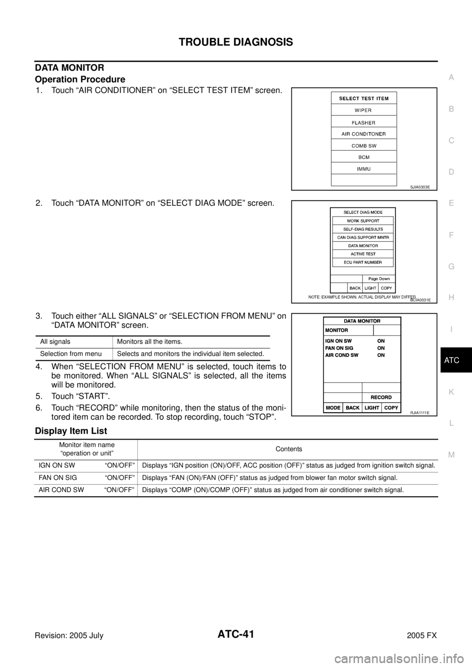
1. Touch “AIR CONDITIONER” on “SELECT TEST ITEM” screen.
2. Touch “DATA MONITOR” on “SELECT DIAG MODE” screen.
3. Touch either “ALL SIGNALS” or “SELECTION FROM MENU” on “DATA MONITOR” screen.
4. When “SELECTION FROM MENU” is selected, touch items to be monitored. When “ALL SIGNALS” is selected, all the items
will be monitored.
5. Touch “START”.
6. Touch “RECORD” while monitoring, then the status of the moni- tored item can be recorded. To stop recording, touch “STOP”.
Display Item List
SJIA0303E
BCIA0031E
All signals Monitors all the items.
Selection from menu Selects and monitors the individual item selected.
R J I A 1111 E
Monitor item name “operation or unit” Contents
IGN ON SW “ON/OFF” Displays “IGN position (ON)/OFF, ACC position (OFF)” status as judged from ignition switch signal.
FAN ON SIG “ON/OFF” Displays “FAN (ON)/FAN (OFF)” status as judged from blower fan motor switch signal.
AIR COND SW “ON/OFF” Displays “COMP (ON)/COMP (OFF)” status as judged from air conditioner switch signal.
Page 488 of 4731
TROUBLE DIAGNOSIS ATC-51
C
D E
F
G H
I
K L
M A
B
AT C
Revision: 2005 July 2005 FX
Auto Amp. Terminals and Reference ValueAJS0014O
Measure voltage between each terminal and ground by referring ter-
minals and reference value for unified meter and A/C amp.
PIN CONNECTOR TERMINAL LAYOUT
TERMINALS AND REFERENCE VALUE FOR UNIFIED METER AND A/C AMP.
RJIA1965E
RJIA1966E
Terminal No. Wire
color Item
Ignition
switch Condition
Voltage
(V)
1 L CAN-H — — —
11 R C A N - L — — —
21 R/W Power supply for BATT OFF — Battery voltage
22 G/R Power supply for IGN ON — Battery voltage
29 B Ground (Power) ON — Approx. 0
30 B Ground ON —- Approx. 0
35 LG/R Power supply for ACC ACC — Battery voltage
39 Y Ambient sensor — — —
40 BR/W In-vehicle sensor — — —
41 P Intake sensor — — —
42 R/Y Compressor ON signal ON A/C switch: ON
(Blower motor operates.) Approx. 0
OFF switch: ON
(A/C system: OFF) Approx. 5
43 G/B A/C LAN signal ON —
HAK0652D
Page 489 of 4731
ATC-52
TROUBLE DIAGNOSIS
Revision: 2005 July 2005 FX
45 PU/W ECV (Electric Control Valve)
signal ON
Self-diagnosis. STEP-4
(Code No. 45)
46 L/W Power supply for IGN2 ON — Battery voltage
49 W/G Sensor ground ON — Approx. 0
50 LG Sunload sensor — — —
53 G Blower motor control signal ON Blower speed: 1st step
54 Y/R Power supply for each door
motor ON — Battery voltage
57 BR/Y Blower motor ON signal ON A/C switch: ON
(Blower motor operates.) Approx. 0
OFF switch: ON
(A/C system: OFF) Approx. 5
Te r m i n a l
No. Wire
color ItemIgnition
switch Condition Voltag e
(V)
RJIA1606E
SJIA0116J
Page 490 of 4731
TROUBLE DIAGNOSIS ATC-53
C
D E
F
G H
I
K L
M A
B
AT C
Revision: 2005 July 2005 FX
Self-diagnosis FunctionAJS0014P
DESCRIPTION
The self-diagnosis system diagnoses sensors, door motors, blower motor, etc. by system line. Refer to appli-
cable sections (items) for details. Shifting from usual control to the self-diagnosis system is accomplished by
starting the engine (turning the ignition switch ON) and pressing OFF switch for at least 5 seconds. The OFF
switch must be pressed within 10 seconds after starting the engine (ignition switch is turned ON). This system
will be canceled by either pressing AUTO switch or turning the ignition switch OFF. Shifting from one step to
another is accomplished by means of pressing temperature switch (driver side), as required.
Shifting from STEP-5 to AUXILIARY MECHANISM is accomplished by means of pressing (fan) UP switch.
RJIA1967E
Page 491 of 4731

ATC-54
TROUBLE DIAGNOSIS
Revision: 2005 July 2005 FX
FUNCTION CONFIRMATION PROCEDURE
1. SET IN SELF-DIAGNOSIS MODE
1. Turn ignition switch ON.
2. Set in self-diagnosis mode as follows. Within 10 seconds after starting engine (ignition switch is turned ON.), press OFF switch for at least 5 seconds.
CAUTION:
�If battery voltage drops below 12 V during diagnosis STEP-3, door motor speed becomes slower
and as a result, the system may generate an error even when operation is normal. To avoid this,
start engine before performing this diagnosis.
�Former STEP-1 (LEDs and display screen are checked) does not exist in this self-diagnosis func-
tion.
>> GO TO 2.
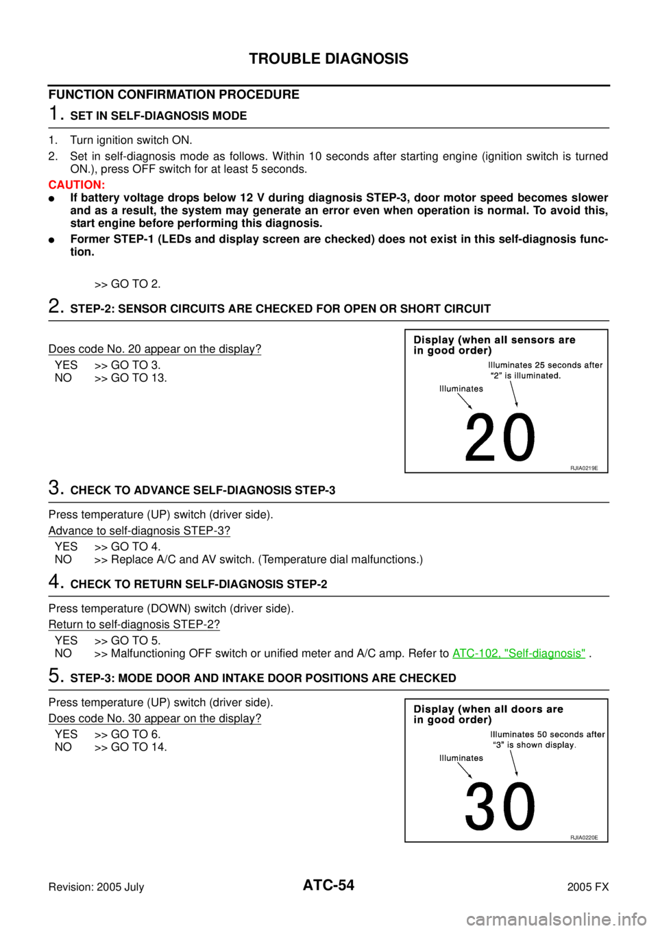
2. STEP-2: SENSOR CIRCUITS ARE CHECKED FOR OPEN OR SHORT CIRCUIT
Does code No. 20 appear on the display?
YES >> GO TO 3.
NO >> GO TO 13.
3. CHECK TO ADVANCE SELF-DIAGNOSIS STEP-3
Press temperature (UP) switch (driver side).
Advance to self
-diagnosis STEP-3?
YES >> GO TO 4.
NO >> Replace A/C and AV switch. (Temperature dial malfunctions.)
4. CHECK TO RETURN SELF-DIAGNOSIS STEP-2
Press temperature (DOWN) switch (driver side).
Return to self
-diagnosis STEP-2?
YES >> GO TO 5.
NO >> Malfunctioning OFF switch or unified meter and A/C amp. Refer to ATC-102, "
Self-diagnosis" .
5. STEP-3: MODE DOOR AND INTAKE DOOR POSITIONS ARE CHECKED
Press temperature (UP) switch (driver side).
Does code No. 30 appear on the display?
YES >> GO TO 6.
NO >> GO TO 14.
RJIA0219E
RJIA0220E